MEMORY OPERATION Section ■ Memory channels ……………………………………………………… ■ Memory channel selection …………………………………………… D Using the [Y]/[Z] keys ……………………………………………… D Using the keypad …………………………………………………… ■ Memory list screen ……………………………………………………… D Selecting a memory channel using the memory list screen …… D Confirming programmed memory channels ……………………… ■ Memory channel programming ……………………………………… D Programming in VFO mode ………………………………………… D Programming in memory mode …………………………………… ■ Frequency transferring ……………
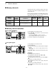
8 MEMORY OPERATION ■ Memory channels The transceiver has 101 memory channels. The memory mode is very useful for quickly changing to oftenused frequencies. All 101 memory channels are tuneable which means the programmed frequency can be tuned temporarily with the main dial, etc. in memory mode. MEMORY CHANNEL MEMORY CHANNEL NUMBER CAPABILITY TRANSFER TO VFO OVERWRITING CLEAR Regular memory channels 1–99 One frequency and one mode in each memory channel.
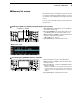
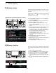
MEMORY OPERATION 8 ■ Memory list screen The memory list screen simultaneously shows 9 memory channels and their programmed contents. 15 memory channels can be displayed in the wide memory list screen. You can select a desired memory channel from memory list screen. D Selecting a memory channel using the memory list screen q Push [EXIT/SET] several times to close a multi-function screen, if necessary. w Push [F-4•MEMORY] to select memory list screen.
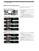
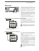
8 MEMORY OPERATION ■ Memory channel programming Memory channel programming can be preformed either in VFO mode or in memory mode. D Programming in VFO mode q Set the desired frequency, operating mode and filter width in VFO mode. w Push [Y]/[Z] several times to select the desired memory channel. [Y] [Z] • Memory list screen is convenient for selecting the desired channel. • Memory channel contents appear in the memory channel readout (below the frequency readout). • “--.---.
MEMORY OPERATION 8 ■ Frequency transferring The frequency and operating mode in a memory channel can be transferred to the VFO. Frequency transferring can be performed in either VFO mode or memory mode. D Transferring in VFO mode This is useful for transferring programmed contents to VFO. TRANSFERRING EXAMPLE IN VFO MODE Operating frequency : 21.320 MHz/USB (VFO) Contents of M-ch 16 : 14.018 MHz/CW q Select VFO mode with [V/M]. w Select the memory channel to be transferred with [Y]/[Z].
8 MEMORY OPERATION ■ Memory names All memory channels (including scan edges) can be tagged with alphanumeric names of up to 10 characters each. Capital letters, small letters, numerals, some symbols ~ (! # $ % & ¥ ? " ’ ` ^ + – ✱ / . , : ; = < > ( ) [ ] { } | _ @) and spaces can be used. D Editing (programming) memory names q Push [EXIT/SET] several times to close a multi-function screen, if necessary. w Push [F-4•MEMORY] to select memory list screen. e Select the desired memory channel.
MEMORY OPERATION 8 ■ Memo pads The transceiver has a memo pad function to store frequency and operating mode for easy write and recall. The memo pads are separate from memory channels. The default number of memo pads is 5, however, this can be increased to 10 in set mode if desired. (p.
SCANS ■ ■ ■ ■ ■ ■ ■ ■ ■ ■ Section Scan types ……………………………………………………………… Preparation ……………………………………………………………… Voice squelch control function ………………………………………… Scan set mode ………………………………………………………… Programmed scan operation ………………………………………… ∂F scan operation ……………………………………………………… Fine programmed scan/∂F scan ……………………………………… Memory scan operation ………………………………………………… Select memory scan operation ……………………………………… Setting select memory channels ……………………………………… D Setting in scan screen ……………………………………………… D Setting in
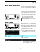
SCANS ■ Scan types • The scan function can be used on the main readout only. • You can operate a scan while operating on a frequency using the dualwatch or split functions. PROGRAMMED SCAN ∂F SCAN Repeatedly scans between two scan edge frequencies (scan edge memory channels P1 and P2). Repeatedly scans within ∂F span area. Scan edge P1 or P2 Start frequency Scan edge P2 or P1 –∂F frequency +∂F frequency Scan Scan Scan Jump Jump This scan operates in VFO mode.
SCANS 9 ■ Voice squelch control function This function is useful when you don’t want unmodulated signals pausing or cancelling a scan. When the voice squelch control function is activated, the receiver checks received signals for voice components. If a receiver signal includes voice components, and the tone of the voice components changes within 1 sec., scan pauses (or stops). If the received signal includes no voice components or the tone of the voice components does not change within 1 sec.
9 SCANS ■ Programmed scan operation q Push [EXIT/SET] several times to close a multi-function screen, if necessary. w Select VFO mode. e Select the desired operating mode. • The operating mode can also be changed while scanning. [SQL] for main [F-1•PROG] [EXIT/SET] r Push [F-5•SCAN] to select the scan screen. t Set the main band’s [SQL] open or closed. Main dial • See page 9-2 for squelch condition. y Push [F-1•PROG] to start the programmed scan. •“ scanning.
SCANS 9 ■ Fine programmed scan/fine ∂F scan Fine scan functions as programmed or ∂F scan, but scan speed decreases when the squelch opens but does not stop. The scanning tuning step shifts from 50 Hz to 10 Hz while the squelch opens. q Push [EXIT/SET] several times to close a multi-function screen, if necessary. w Push [F-5•SCAN] to select the scan screen. e Set for programmed scan or ∂F scan as described on previous page. r Push [F-1•PROG] or [F-2•∂F] to start a scan. •“ ” or “ blink while scanning.
9 SCANS ■ Memory scan operation q Push [EXIT/SET] several times to close a multi-function screen, if necessary. w Select memory mode. e Push [F-5•SCAN] to select the scan screen. r Set the main band’s [SQL] open or closed. • See page 9-2 for squelch condition. t Push [F-1•MEMO] to start the memory scan. [SQL] for main [F-1•MEMO] [EXIT/SET] •“ ning.
SCANS 9 ■ Setting select memory channels D Setting in scan screen q Push [EXIT/SET] several times to close a multi-function screen, if necessary. w Select memory mode. e Push [F-5•SCAN] to select the scan screen. r Select the desired memory channel to set as a select memory channel. • [Y]/[Z] keys and direct keypad selections can be used. t Push [F-3•SELECT] several times to set the memory channel as a select memory ★1, ★2, ★3 or not.
9 SCANS ■ Tone scan The transceiver can detect the subaudible tone frequency in a received signal. By monitoring a signal that is being transmitted on a repeater input frequency, you can determine the tone frequency required to access the repeater. q Set the desired frequency or memory channel to be checked for a tone frequency. w Push [AM/FM] several times to select FM mode. e Push [TONE] for 1 sec. to enter tone frequency screen.
ANTENNA TUNER OPERATION Section 10 ■ Antenna connection and selection ………………………………… ■ Antenna memory settings …………………………………………… D Antenna type selection …………………………………………… D Temporary memory ………………………………………………… D Antenna selection mode …………………………………………… ■ Antenna tuner operation ……………………………………………… D Tuner operation …………………………………………………… D If the tuner cannot tune the antenna …………………………… 10-1 10-2 10-3 10-3 10-4 10-4 10-5 10-5 10-6
10 ANTENNA TUNER OPERATION ■ Antenna connection and selection The IC-7800 has 4 antenna connectors for the HF/50 MHz bands, [ANT1], [ANT2], [ANT3], and [ANT4]. [ANT] For each operating band the IC-7800 covers, there is a band memory which can memorize a selected antenna. When you change the operating frequency beyond a band, the previously used antenna is automatically selected (see below) for the new band. This function is convenient when you use 4 antennas for HF and 50 MHz bands operation.
ANTENNA TUNER OPERATION 10 ■ Antenna memory settings Storing the antenna connector number for each frequency band to suit your antenna system. [ANT] q Push [EXIT/SET] several times to close multi-function screen, if necessary. w Push [ANT] for 1 sec. to select antenna set screen. e Select the desired frequency band with a band key. r Push [ANT] several times to select the desired antenna number that you want to set for the selected frequency band. Band keys • “★” appears.
10 ANTENNA TUNER OPERATION ■ Antenna memory settings (continued) D Temporary memory The antenna temporary memory memorize the manually selected antenna. The selected antenna will be recalled even the frequency band has been changed. q Select the antenna set screen. w Push [F-4•TEMP-M] to turn the temporary memory ON and OFF. e Select the desired frequency band with a band key. r Push [ANT] to select the desired antenna. • “★” appears when a different antenna from the original is selected.
ANTENNA TUNER OPERATION 10 ■ Antenna tuner operation The internal automatic antenna tuner matches the transceiver to the connected antenna automatically. Once the tuner matches an antenna, the variable capacitor angles are memorized as a preset point for each frequency range (100 kHz steps). Therefore, when you change the frequency range, the variable capacitors are automatically preset to the memorized point. CAUTION: NEVER transmit with the tuner ON when no antenna is connected.
10 ANTENNA TUNER OPERATION ■ Antenna tuner operation (continued) • PTT TUNER START The tuner is always tuned when the PTT is pushed after the frequency is changed (more than 1% from last-tuned frequency). This function removes the “push and hold [TUNER]” operation and activates for the first transmission on a new frequency. This function is turned ON in set mode. (p. 12-14).
CLOCK AND TIMERS ■ ■ ■ ■ Section 11 Time set mode ………………………………………………………… Daily timer setting ……………………………………………………… Setting sleep timer …………………………………………………… Timer operation ………………………………………………………… 11-1 11-2 11-3 11-4 11-4
11 CLOCK AND TIMERS ■ Time set mode The IC-7800 has a built-in calender and 24-hour clock with daily power ON/OFF timer functions. Before operating these timer functions, set the current date and time, etc. [ABC]/[abc] [123]/[Symbol] [F-3•Ω ≈][F-5•EDIT]/[F-5•SET] [F-1•Y] [F-2•Z] [F-4•DEF] [EXIT/SET] q Push [EXIT/SET] to close multi-function screen, if necessary. w Push [F-7•SET] to select set mode menu screen. e Push [F-4•TIME] to select time set mode.
CLOCK AND TIMERS 11 ■ Daily timer setting The transceiver turns power ON and/or OFF automatically on the specified day of the week and time with the specified frequency settings in each main and sub readout. q Push [EXIT/SET] several times to close multi-function screen, if necessary. w Push [TIMER] for 1 sec. to select timer set screen. e Push one of [F-1•TIMER1] to [F-4•TIMER4] to select the desired timer. r Rotate the main dial to select the timer action ON and OFF.
11 CLOCK AND TIMERS ■ Setting sleep timer The sleep timer turns the transceiver power OFF automatically after passing the set period. The timer can be set to 5–120 min. in 5 min. steps. q Push [EXIT/SET] several times to close a multi-function screen, if necessary. w Push [TIMER] for 1 sec. to select timer set screen. e Push [F-7•SLEEP] to select the sleep timer set condition. [F-4•CLR] [F-7•SLEEP]/[F-7•SET] • “– – –” blinks. r Set the desired time period using the main dial.