MXR-5000T / Page 13-1-1 INSTRUCTION MANUAL MARINE RADAR MXR-5000R (Radome type) MXR-5000T (Open array type) This device complies with Part 15 of the FCC Rules. Operation is subject to the condition that this device does not cause harmful interference.
MXR-5000T / Page 13-1-2 FOREWORD SUPPLIED ACCESSORIES Thank you for purchasing Icom’s MXR-5000R/T rine radar. ma- The radar is designed for use with the Icom MarineCommander™ system through the supplied connection cable. It has powerful transmission power, and many other advanced features can be used with the Icom MarineCommander™ system. IMPORTANT READ THIS INSTRUCTION MANUAL CAREFULLY before attempting to operate the radar. SAVE THIS INSTRUCTION MANUAL.
MXR-5000T / Page 13-1-3 PRECAUTIONS For radar unit: For Scanner unit: R WARNING! NEVER let metal, wire or other objects touch any internal part or terminals of the radar unit. This may result in an electric shock. R DANGER: HIGH VOLTAGE! NEVER open the scanner unit. The scanner unit contains high voltage that could be fatal. And there are no user adjustment points. All repairs and adjustments MUST be made by a qualified electronics technician at your Marine Navigation Dealer.
MXR-5000T / Page 13-1-4 RADAR OPERATOR WARNING Icom requires the radar operator to meet the FCC Requirements for Radio Frequency Exposure. A slotted waveguide array antenna with gain not greater W ARN ING than 27 dBi must be mounted a minimum of 5.5 meters (measured from the lowest point of the antenna) vertically above the main deck and all possible personnel. This is the minimum safe separation distance estimated to meet all RF exposure compliance requirements. This 5.
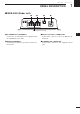
MXR-5000T / Page 13-1-5 PANEL DESCRIPTION 1 ■ MXR-5000 (Radar unit) q w e r This terminal is not used. q DC POWER INPUT TERMINALS Connect the 12 V/24 V DC power supply through the supplied DC power cable. e MarineCommander™ CONNECTOR Connect this connector to the Icom MarineCommander™. w GROUND TERMINALS Connect these terminals to ground to prevent electrical shocks. r SCANNER UNIT CONNECTOR Connect this connector to the supplied scanner unit.
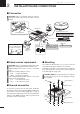
MXR-5000T / Page 13-1-6 2 INSTALLATION AND CONNECTIONS ■ Connection CAUTION: Before connecting, make sure disconnecting the radar unit’s DC power cable from the battery. Ground Radar unit Supplied scanner unit Terminal guard NEVER connect anything other than the supplied scanner unit. Detach the terminal guard first. MarineCommander™ MXP-5000 NOTE: Use the ter minals as shown below for the cable connections.
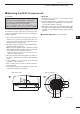
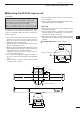
MXR-5000T / Page 13-1-7 INSTALLATION AND CONNECTIONS 2 ■ Mounting the EX-2714 scanner unit D Location D Mounting q Drill four holes of 12 mm (1⁄2 in) in diameter using the supplied template. w If the mounting surface or platform is metal, apply sealing compound around the holes to prevent corrosion and to waterproof the unit. e Attach the scanner unit to the selected position with the supplied bolts (M10×50 mm or M10×25 mm����� ; depending on your installation needs), flat and spring washers.
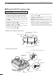
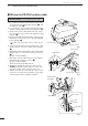
MXR-5000T / Page 13-1-8 2 INSTALLATION AND CONNECTIONS ■ Wiring the EX-2714 system cable CAUTION: NEVER cut the supplied system cable. q Using a hex head wrench*, loosen the four bolts on the bottom of the scanner unit, and open the unit. * Phillips head or flathead screwdriver is also usable. w Loosen the sealing nut on the scanner unit and pass the system cable through the sealing nut and tube. (q) e Insert the black and white PA cable connector into the PA unit connector J1.
MXR-5000T / Page 13-1-9 2 INSTALLATION AND CONNECTIONS ■ Mounting the EX-2780 scanner unit D Location * The radar’s power automatically turns OFF approx. 30 sec. after the display unit’s power is turned OFF. W hen 2 display units are connected to the MarineCommander™, all units’ power must be turned OFF. The scanner unit is designed for high-pressure water jet resistance (except for the cable connectors). Select a place for installation which meets the following important conditions.
MXR-5000T / Page 13-1-10 2 INSTALLATION AND CONNECTIONS ■ Wiring the EX-2780 system cable CAUTION: NEVER cut the supplied system cable. q Loosen the four bolts on the bottom of the scanner body using the supplied allen wrench (q), and open the top cover (w). w Loosen the nut on the scanner unit and pass the system cable through the nut and sealing tube. (e) e Connect the power cable (black and red) connector to the power unit connector through the looped cable tie.
MXR-5000T / Page 13-1-11 INSTALLATION AND CONNECTIONS 2 ■ Attaching the EX-2780 scanner unit q Put the scanner unit on the stay, then attach the antenna rotor with the supplied bolts (M8×18 mm), flat and belleville washers and a sealing washer. Be sure to install the belleville washer in the direction as shown below. (Fig. 1) w Apply the lubricant specified below, or an equivalent one, to the motor bearing, if required.
3 MXR-5000T / Page 13-1-12 MAINTENANCE AND OPTIONS Continued, reliable operation of the radar depends on how you care for your equipment. The simple maintenance tips that follow can help you save time and money, and avoid premature equipment failures. R WARNING! BE SURE the radar’s power is OFF* before performing any maintenance. * The radar’s power automatically turns OFF approx. 30 sec. after the display unit’s power is turned OFF.
MXR-5000T / Page 13-1-13 SPECIFICATIONS D Radar unit • DC input voltage • Power consumption • Usable temperature range • Dimensions (projections not included) • Weight (approx.) 4 : 10.8 V to 31.2 V DC : Less than 5.0 A at 12.0 V (MXR-5000R) Less than 5.5 A at 12.0 V (MXR-5000T) : –20°C to +60°C; –4˚F to 140˚F : 250(W)×67(H)×200(D) mm; 927⁄32(W)×25⁄8(H)×77⁄8(D) in : 2.1 kg; 4.
MXR-5000T / Page 13-1-14 MEMO
MXR-5000T / Page 13-1-15 MEMO
MXR-5000T / Page 13-1-16 A-6752H-1EX-w Printed in Japan © 2009–2010 Icom Inc.
MXR-5000T / Page 13-2-1 INSTRUCTION MANUAL MARINE PLOTTER MXP-5000 DISPLAY UNIT MXD-5000 This device complies with Part 15 of the FCC Rules. Operation is subject to the following two conditions: (1) this device may not cause harmful interference and (2) this device must accept any interference received, including interference that may cause undesired operation.
MXR-5000T / Page 13-2-2 PRECAUTIONS R WARNING! NEVER let metal, wire or other objects touch any internal part or terminals of the Main unit. This may result in an electric shock. R WARNING! NEVER apply AC voltage to the DC input terminals of the Main unit. This may pose a fire hazard, result in an electric shock or damage the Main unit. R WARNING! NEVER apply more than 32 V DC to the DC input terminals of the Main unit or use reverse polarity. This may pose a fire hazard or damage the Main unit.
MXR-5000T / Page 13-2-3 PANEL DESCRIPTION 1 ■ MXP-5000 (Main unit) r t BLACK BOX 1 2 SUB 3 DISPLAY MAIN 4 1 EXT-DISPLAY e q GROUND TERMINAL Connect this terminal to ground to prevent electrical shocks. w DC POWER INPUT TERMINALS Connect the 12 V/24 V DC power supply through the supplied DC power cable. e DISPLAY UNIT CONNECTOR Connect this connector to the Display unit (MXD5000). Two Display units can be connected.
MXR-5000T / Page 13-2-4 1 PANEL DESCRIPTION ■ MXD-5000 (Display unit) BRILL WPT MOB RANGE e SUB r t y u i FOCUS LAYOUT q POWER/DISPLAY BLLIANCE SWITCH [ /BRILL] • While the MarineCommander’s power is OFF Push to turn ON the MarineCommander’s power. • While the MarineCommander’s power is ON ➥ Push to turn the Radar second menu. • Display Brilliance, Radar TX setting, Panel Brilliant and Color Palette are available.
MXR-5000T / Page 13-2-5 INSTALLATION AND CONNECTIONS 2 ■ Connection CAUTION: Before connecting, make sure disconnecting the DC power cable from the battery.
3 MXR-5000T / Page 13-2-6 BASIC OPERATION ■ Turning power ON/OFF q Push [ ] to turn the power ON. • The initial screen and WARNING screens appear. w Push [ENTER] to start operation. • The warming up screen appears. • The magnetron inside the scanner unit warms up for 90 seconds. e When the warming up is complete, the operating screen appears to start operation. q I f any other than Radar screen appears, hold down [LAYOUT](FOCUS) for 2 seconds to enter the screen selection mode.
MXR-5000T / Page 13-2-7 BASIC OPERATION 3 ■ Basic operation t P ush [ENTER], and then [u] once to select the Sea menu, to set the sensitivity time control, rotate [DIAL] counterclockwise to set the SEA to minimum. BRILL [ ] MOB [LAYOUT] RANGE FOCUS LAYOUT [+] or [–] (RANGE) [�] SUB [MENU] MENU CAUTION: When setting of the SEA to a fully clockwise position, close targets are blanked. WPT CLEAR [CLEAR] [ENTER] q Turn the power ON. w Turn the Radar TX ON.
MXR-5000T / Page 13-2-8 3 BASIC OPERATION The following are typical basic operation examples, which may hinder radar reception (sea clutter, precipitation interference and echoes from other radar). ■ RAIN function (MENU w Gain u Rain...) his function eliminates reflection echoes from rain, T snow, fog etc. q P ush [MENU], and then [ENTER], to enter the Gain menu. w R otate [DIAL] until the “Rain...” menu becomes highlighted. e Push [ENTER] to turn the Rain level indicator.
MXR-5000T / Page 13-2-9 BASIC OPERATION 3 ■ IR function (MENU w Radar Setup u Signal Process u IR) adar interference may appear when another ship’s R radar is operating on the same frequency band in close proximity. The IR function can eliminate this type of interference. Radar interference With IR function ON q Push [MENU] to enter the Menu screen. w R otate [DIAL] until the “Radar Setup” menu becomes highlighted.
MXR-5000T / Page 13-2-10 3 BASIC OPERATION ■ TRAILS function (MENU w Trail) The trails function memorizes echoes continuously or at constant intervals. This is useful for watching other ships’ tracks, approx. relative speed, etc. Trail time • Setting the trail interval time (MENU w Trail u Trail Setup u Trail Time) q Push [MENU] to enter the Menu screen. w R otate [DIAL] until the “Trail” menu becomes highlighted. e P ush [ENTER] then rotate [DIAL] until the “Trail Setup” menu becomes highlighted.
MXR-5000T / Page 13-2-11 BASIC OPERATION 3 ■ Long pulse function (MENU w Radar Setup u Signal Process u Pulse) To magnify the blips for easier viewing of small targets, the long pulse and echo stretch functions are available. When the long pulse is used in the 3⁄4 to 2 NM range, this function magnifies target echoes to the backward direction of the target. • Pulse selection q Push [MENU] to enter the Menu screen. w R otate [DIAL] until the “Radar Setup” menu becomes highlighted.
MXR-5000T / Page 13-2-12 4 DISTANCE AND DIRECTION MEASUREMENTS ■ Distance measurement TYPE DESCRIPTION RING Displays fixed rings. Suitable for rough estimations from your own ship to any target. VRM1 Displays a variable range marker and activated by the [DIAL] for the range marker selector. Suitable for accurate measurements from your own ship to a target. VRM2 Normally functions the same as VRM1. When the VRM1 and EBL1 selects a target, the center of VRM2 appears at the intersection point.
MXR-5000T / Page 13-2-13 DISTANCE AND DIRECTION MEASUREMENTS D Using the variable range marker 4 q Push [MENU] to enter the Menu screen. w Rotate [DIAL] until the “EBL/VRM” menu becomes highlighted. e P ush [ENTER] then rotate [DIAL] until the “VRM1...” menu (or “EBL1...” menu) becomes highlighted. r Push [ENTER] then rotate [DIAL] to set the marker. • The yellow dotted circle appears. (Or yellow dotted line appears.) • The range between the ship and the target is displayed in the VRM1 readout.
5 MXR-5000T / Page 13-2-14 BASIC RADAR THEORY Radar uses a form of electromagnetic radiation, which like light, can be reflected. Because of this property, some objects may cause false echoes on the screen where in fact no targets actually exist. These echoes may appear if a large vessel, bridge, or tank is in proximity. Operators should be familiar with the effects of these phenomena. In some cases, echoes can be reduced.
MXR-5000T / Page 13-2-15 BASIC RADAR THEORY 5 ■ Multiple echoes Multiple echoes may appear when a short-range and strong echo is received from a ship, bridge, or breakwater. Multiple echoes will appear beyond the target’s true echo point on the same bearing of a large target. They can be reduced with proper adjustment of the [SEA] control. False echoes Own ship True echo Another ship 1 2 3 4 ■ Minimum range 5 Detection at short range is very important.
MXR-5000T / Page 13-2-16 5 BASIC RADAR THEORY ■ Blind and Shadow sectors Blind or Shadow sectors may exist because of obstructions such as masts, derricks or stacks. An obstruction may throw either a complete or partial shadow as shown in the diagram below. If a target is in a shadow sector, target echoes may not appear on the screen. Shadow sector When tall and massive targets such as a large island are located at close range also shadowed without producing any echoes.
MXR-5000T / Page 13-2-17 MEMO 1 2 3 4 5 6 7 8 9 10 11 12 13 14 15 16 17 18 19 20 21 15
MXR-5000T / Page 13-2-18 A-6????-1EX Printed in Japan © 2010 Icom Inc.