
User's Manual
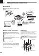
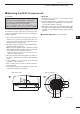
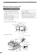
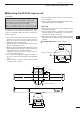
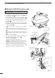
Table Of Contents

CAUTION: NEVER cut the supplied system cable.
q Loosen the four bolts on the bottom of the scan-
ner body using the supplied allen wrench (q), and
open the top cover (w).
w Loosen the nut on the scanner unit and pass the
system cable through the nut and sealing tube. (e)
e Connect the power cable (black and red) connec-
tor to the power unit connector through the looped
cable tie. (r)
r Insert the PA cable (black and white) connector into
the PA unit connector. Be sure to follow the diagram
below carefully. (t)
• Secure the looped PA cable with the looped cable tie
(y).
t Connect the shielded cable ground wire to the
chassis with the screw as shown in the diagram.
(u)
y Clamp the system cable with the cable clamp metal
fitting using a screw near the sealing connector.
(i)
Be sure to clamp it tightly.
u Clamp the system cable with the ferrite bead at-
tached near the sealing connector. (o)
Be sure to clamp it tightly.
Secure the ferrite bead with cable tie.
i Tighten the sealing-nut, then close the top cover.
DO NOT stretch the system cable too much, other-
wise miss contact of the connector may occur.
o Tighten the four bolts on the bottom of the scanner
body. (Use a torque wrench until the scale on the
wrench reads torque to 9.8 N•m; 7.23 lbf•ft.)
Allen wrench
Scanner body
q
w
Ferrite bead
Cable tie
Cable clamp
i
o
Sealing tube
Sealing Nut
e
Shielded cable
ground wire
System cable
u
r
t
Looped
cable tie
Power cable
PA cable
y
■ Wiring the EX-2780 system cable
Fig.1
Fig.2
Fig.3
6
2
INSTALLATION AND CONNECTIONS
MXR-5000T / Page 13-1-10