
User's Manual
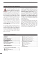
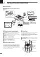
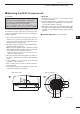
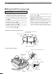
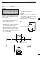
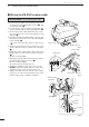
Table Of Contents

2
2
INSTALLATION AND CONNECTIONS
■ Connection
CAUTION: Before connecting, make sure discon-
necting the radar unit’s DC power cable from the
battery.
12 V/24 V
battery
Radar unit
KEEP the terminal
guard attached after
connecting cables.
NOTE: Use the termi-
nals as shown below for
the cable connections.
Solder
Crimp
Tu rn the power OFF.
Ground
NEVER connect anything other
than the supplied scanner unit.
Supplied scanner unit
MarineCommander™
MXP-5000
Te rminal guard
GND
DC IN
12V/24V
NC
Detach the terminal guard first.
■ Power source requirement
CAUTION: Before connecting the DC power cable,
check the following important items. Make sure:
• Output voltage of the power source is 12 V/24 V
DC.
• DC power cable polarity is correct.
Red : Positive + terminal
Black : Negative _ terminal
• Fuse rating of the DC power cable is correct. (The
10 A fuse is pre-installed.)
5 A : For 24 V power source
10 A : For 12 V power source
■ Ground connection
To prevent electrical shocks and other problems,
ground the radar unit through the [GND] terminal. For
best results, connect a heavy gauge wire or strap to
the nearest grounding point on the boat. The distance
between the [GND] terminal and the ground point
should be as short as possible.
■ Mounting
First, drill four Ø5.5–6 mm (
7
⁄32–
1
⁄4") holes to mount
the radar unit using the units base as a pattern.
Mount the radar unit securely with the four supplied
bolts (M5×30 mm) to a flat surface which supports
more than approx. 5 kg (11 lb).
CAUTION: KEEP the radar unit at least 1.8 meter
(5.9 ft) away from your vessel’s magnetic naviga-
tion compass.
Flat washer
Flat washer
Spring washer
Spring washer
Bolt
Nut
MXR-5000T / Page 13-1-6