
User's Manual
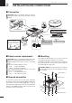
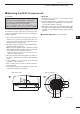
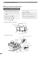
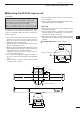
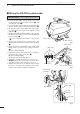
Table Of Contents

■ Wiring the EX-2714 system cable
CAUTION: NEVER cut the supplied system cable.
q Using a hex head wrench*, loosen the four bolts on
the bottom of the scanner unit, and open the unit.
* Phillips head or flathead screwdriver is also usable.
w Loosen the sealing nut on the scanner unit and
pass the system cable through the sealing nut and
tube. (q)
e Insert the black and white PA cable connector into
the PA unit connector J1. (w)
r Connect the shielded cable ground wire to the
ground plate with the screw. (e)
t Clamp the system cable with the ferrite bead at-
tached near the sealing connector.
Be sure to clamp it tightly. (r)
y Connect the power cable (black and red) to the
power connector. (t)
u Tighten the sealing nut, then replace the radome
cover over the scanner unit.
DO NOT stretch the system cable too much, other-
wise miss contact of the connector may occur.
i Tighten the four bolts on the bottom of the scanner
unit. (Use a torque wrench until the scale on the
wrench reads torque to 5.0 N•m; 3.69 lbf•ft.)
• The four projections around the circumference of the ra-
dome cover show the positions of the bolt receptacles.
• Scanner unit assembly (cover removed)
Ship’s bow direction
Face the Ω mark in the direction
of the ship’s bow.
Stern
System cable
Scanner unit assembly
Bolt
• Connect the system cable
Ferrite bead
Shielded cable
ground wire
w
t
PA cable
Power
connector
e
Power cable
PA cable (Loop the PA cable twice.)
q
r
Sealing tube
Sealing nut
System cable
4
2
INSTALLATION AND CONNECTIONS
MXR-5000T / Page 13-1-8