MR-1010RII / Page 13-1 INSTRUCTION MANUAL MARINE RADAR MR-1010R™
MR-1010RII / Page 13-2 SYSTEM COMPONENTS MODEL NAME DISPLAY UNIT SCANNER UNIT MR-1010RII 10.4-inch Color LCD EX-2714 (Radome type) SUPPLIED ACCESSORIES zz10.4-inch Color LCD display unit 1. 2. 3. 4. 5. 6. 7. 8. 9. 10. 11. 12. Quantity NMEA connector (PLT-167-P-R) ......................... 1 NMEA connector (PLT-168-P-R).......................... 1 Spare fuse (FGB 15 A, for 12 V DC) ................... 1 Spare fuse (FGB 5 A, for 24 V DC)...................... 1 DC power cable .....................
MR-1010RII / Page 13-3 The MR-1010RII is a supplemental aid to navigation and is not intended to be a substitute for accurate and current nautical charts. Thank you for choosing this Icom product. The MR-1010RII marine radar is designed and built with Icom's state of the art technology and craftsmanship. With proper care, this product should provide you with years of trouble-free operation. IMPORTANT READ ALL INSTRUCTIONS carefully and completely before using the radar.
MR-1010RII / Page 13-4 PRECAUTIONS For Display unit: iii RRWARNING! NEVER let metal, wire or other objects contact the inside of the display unit, or make incorrect contact with connectors on the rear panel. This could cause an electric shock or damage the display unit. RRWARNING! NEVER apply AC voltage to the DC connector of the display unit. This could cause a fire or damage the display unit. RRWARNING! NEVER apply more than 42 V DC to the DC connector of the display unit.
MR-1010RII / Page 13-5 TABLE OF CONTENTS SYSTEM COMPONENTS........................................... i SUPPLIED ACCESSORIES........................................ i DISPOSAL................................................................... i ABOUT CE AND DOC................................................. i IMPORTANT................................................................ii FEATURES..................................................................ii EXPLICIT DEFINITIONS.........................
1 MR-1010RII / Page 13-6 PANEL DESCRIPTIONS ■■Front panel q !8 q !8 w !7 w !7 e !6 e !6 r !5 t t y y !4 u !4 u !3 i !3 i !2 o !2 o !1 !0 !1 !0 Control panel (English) q POWER KEY (p. 7) zzPush to turn the radar power ON or OFF. ••The initial screen is displayed and a beep sounds after the power has been turned ON. w TRANSMIT/SAVE KEY [TX (SAVE)]/ [ ] zzPush to change the operating mode between TX mode and the standby mode. (p.
MR-1010RII / Page 13-7 PANEL DESCRIPTION i EBL2 (VRM2) KEY [EBL2 (VRM2)]/ ] (pp. 17–20) [ zzPush to display the EBL2 and the VRM2. EBL: Electronic Bearing Line VRM: Variable Range Marker ••Push [t] or [u] to adjust the EBL selector, or push [p] or [q] to adjust the VRM selector. Then push [ENTER]/[ ] to set the point. ••The EBL2 bearing and the VRM2 distance are displayed in the lower right corner of the screen.
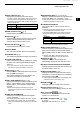
MR-1010RII / Page 13-8 1 PANEL DESCRIPTION ■■Screen q w e r t y u i @7 @6 @5 @4 o !0 !1 !2 !3 @3 !4 @2 !5 @1 !6 @0 !7 !8 q SCREEN RANGE READOUT (p. 17) Displays the range of the current screen. Indicator NM km Indicator LLThe distance unit can be selected in the Initial menu. w FIXED RING RANGE READOUT (p. 17) Displays the interval range of the fixed ring. Indicator H-UP C-UP N-UP TM Head-up Course-up North-up True Motion !9 r HEADING INDICATOR (p.
MR-1010RII / Page 13-9 PANEL DESCRIPTION i TRAILS INDICATOR (p. 12) Displays the trail reference and the trail time. ••The echo remains, with gradation, during the period of trail time on the screen. (Except for the trail time: ∞) ••Progressing time counter starts counting until the timer reaches the trail time. Indicator T M True Magnetic Description o RAIN CONTROL ICON (p. 9) Displayed when the RAIN function is used. !0 SEA ICON (p. 9) Displayed when the SEA control function is used.
MR-1010RII / Page 13-10 1 PANEL DESCRIPTION ■■ Screen (Continued) #2 #38 #4 @8 #1 #5 @9 #0 @8 OWN SHIP VECTOR INDICATOR (p. 6) Displays the vector of your own ship. @9 PARALLEL INDEX LINES (p. 17) Displayed when the Parallel Index line (PI) function is used. Used to measure the direction and interval of the parallel index lines #0 PI READOUTS (p. 17) Displays the direction and interval of the parallel index lines when the Parallel Index line (PI) function is set.
MR-1010RII / Page 13-11 PANEL DESCRIPTION 1 1 2 3 4 5 #8 6 #6 7 8 9 #7 #6 ALARM ZONE (p. 14) Displays the alarm zone. • Displays when the alarm function is used. #7 WARNING MESSAGE (p. 22) Displayed at the bottom of the screen when an alarm sounds in case such as a vessel is entered into the zone that you have set. 10 11 #8 POPUP MESSAGE (p. 32) A message pops up when the radar received the data of the target, such as a DSC, or favorite AIS that you have selected.
2 MR-1010RII / Page 13-12 BASIC OPERATION ■■ Turning the Power ON or OFF Refer to Chapter 14 in this manual about the installation and connections. (pp. 54–60) Turning ON the power 1. Push [ ] to turn ON the power. ••The magnetron inside the scanner unit warms up for 90 seconds and the warm-up time is counted down on the screen. When the countdown is completed, the Standby screen is displayed. Warm-up time ■■Basic operation 1. Turn ON the power.
MR-1010RII / Page 13-13 BASIC OPERATION 2 ■■ Adjusting brilliance and color DDAdjusting the display brilliance The brilliance of the screen can be adjusted. When you require continuous operation, but not constant viewing, a lower setting can increase the life of the LCD. 1. Push [BRILL]/[ adjustment box. ] to open the Brilliance/Color DDSelecting the display color The Day (white background), Night (black background), and User settings are selectable. 1. Push [BRILL]/[ adjustment box.
MR-1010RII / Page 13-14 2 BASIC OPERATION ■■Adjusting the screen The followings are typical basic operation examples that may hinder radar reception (sea clutter, precipitation interference and echoes from other radar). See also Basic Radar Theory in Chapter 9 (pp. 47–49) DDRAIN function This function eliminates echoes from rain, snow, fog, and so on. zzRotate the RAIN / control fully counterclockwise to deactivate the control function. ••The RAIN icon ( DDAdjusting the GAIN ) disappears.
MR-1010RII / Page 13-15 BASIC OPERATION 2 ■■OFF CENTER function The scanning area can be shifted in direction and can be partially enlarged. This is useful when the Head-up screen is selected, and you want to enlarge the bow direction display, or the center of the screen shifts in the direction of the intersection. 1 2 LLThis function is selectable in 24 NM or shorter ranges. LLThis function is not selectable in the TM screen. 1. Push [OFF CENT]/[ 2. Push [OFF CENT]/[ normal screen.
MR-1010RII / Page 13-16 2 BASIC OPERATION ■■Echo Stretch function The blips can be magnified electronically for easier viewing of small targets. (MENU w Video w Echo Stretch) 1. 2. 3. 4. Push [MENU]/[ ] to display the Menu screen. Push [t] or [u] to select the Video menu. Push [p] or [q] to select the “Echo Stretch” item. Push [ENTER]/[ ] to enter the option selection mode. 5. Push [t] or [u] to select the Echo Stretch ON. 6. Push [ENTER]/[ ] to save the setting. 7.
MR-1010RII / Page 13-17 BASIC OPERATION 2 ■■Trail function The trail function memorizes echoes continuously or at constant intervals. This is useful for watching other vessels’ tracks, approximate relative speed and so on. DDUsing the Trail function 1. Push [TRAILS]/[ function. ] to turn ON the Trail ••The trail indicator and the trail interval are displayed in the upper left of the screen. ••The trail interval counter starts to count up to the trail time. 1.
MR-1010RII / Page 13-18 2 BASIC OPERATION ■■Power save function The power save function conserves the vessel's battery power by pausing the transmission. The standby (pausing) times are selectable (rotation number is fixed to 10). For example, when 1 minute is selected, the scanner rotates 10 revolutions, then stops for 1 minute, and then repeats this sequence while the power save mode is activated. DDSetting the scanning standby time 1. 2. 3. 4.
MR-1010RII / Page 13-19 BASIC OPERATION 2 ■■Ship speed indication When the ship speed data in NMEA 0183 format is applied, the radar can display the ship speed. (MENU w Initial w Speed Unit) 1 1. 2. 3. 4. Push [MENU]/[ ]. Push [t] or [u] to select the Initial menu. Push [p] or [q] to select the “Speed Unit” item. Push [ENTER]/[ ] to enter the option selection mode. 5. Push [t] or [u] to select the speed unit. 2 3 4 LLknot (kn) or kilometers/hour (km/h) is selectable. 6. Push [ENTER]/[ 7.
MR-1010RII / Page 13-20 2 BASIC OPERATION ■■Bearing settings The radar bearing interface accepts NMEA, N+1, AUX, or COG data format and the bearing can use a magnetic or true north type. When a true north type bearing is used, the variation from magnetic north can be adjusted on 0.1˚ steps. DDSetting the bearing input 1. Push [MENU]/[ ]. 2. Push [t] or [u] to select the Initial menu. 3. Push [p] or [q] to select the “Bearing Input ” item. 4. Push [ENTER]/[ ] to enter the option selection mode. 5.
MR-1010RII / Page 13-21 BASIC OPERATION 2 DDSetting the magnetic variation 1. 2. 3. 4. Push [MENU]/[ ]. Push [t] or [u] to select the System menu. Push [p] or [q] to select the “Variation” item. Push [ENTER]/[ ] to enter the option selection mode. 5. Push [t] or [u] to select the bearing variation. LL“Auto”* and “Manual” are selectable. 6. Push [ENTER]/[ ] to save the setting. 7. When the “Manual” option is selected in step 4, push [q] to select the “Manual Variation,” then push [ENTER]/[ ]. 8.
MR-1010RII / Page 13-22 3 DISTANCE AND DIRECTION MEASUREMENTS ■■Distance measurement Various ways to measure the distance are provided with this radar. LLYou can select a distance unit from nautical miles (NM), or kilometers (km) in the Initial menu (p. 45). TYPE DESCRIPTION Displays fixed rings. Suitable for rough estimations from your own vessel to any target. Selectable from two types of range rings.
MR-1010RII / Page 13-23 DISTANCE AND DIRECTION MEASUREMENTS 3 DDUsing the variable range marker 1. Push [EBL1 (VRM1)]/[ ] to display the VRM1 and EBL1, then push [p] or [q] to set the marker. ••The range between the vessel and the target is indicated in the EBL/VRM1 readout. 2. Push [ENTER]/[ ] to set the EBL/VRM1 setting. 3. Push [EBL2 (VRM2)]/[ ] to display the VRM2 and EBL2, then push [p] or [q] to set the marker. 4. Push [ENTER]/[ ] to set the EBL/VRM2 setting. 5.
MR-1010RII / Page 13-24 3 DISTANCE AND DIRECTION MEASUREMENTS ■■Advanced measurements Using both Electronic Bearing Lines (EBL) and both Variable Range Markers (VRM), the following advanced measurements can be made. DDMeasuring the distance and direction between two targets 1. Move the cursor onto the target. 2. Push [EBL1 (VRM1)]/[ the EBL1 and VRM1. ] to display LLPush [t] or [u] to rotate the Electronic Bearing Line. LLPush [p] or [q] to increase or decrease the Variable Range Marker ring size. 3.
MR-1010RII / Page 13-25 DISTANCE AND DIRECTION MEASUREMENTS 3 DDMeasuring the distance and course from a waypoint 1. Display a waypoint as described on page 14. 2. Push [EBL1 (VRM1)]/[ ] to display the EBL1 and VRM1, and then set the VRM1 and EBL1 to the waypoint. ••Push [t] or [u] to rotate the Electronic Bearing Line. LLPush [p] or [q] to increase or decrease the Variable Range Marker ring size. 3. Push [ENTER]/[ ] to set the VRM/EBL1 setting. 4.
4 MR-1010RII / Page 13-26 ALARM FUNCTION The unit has an alarm function to protect your vessel from collisions. If other vessels, islands, or other obstructions come into the preset alarm zone, the function alerts you with an alarm. You can set the range and bearing for up to two alarm zones. While the alarm function is activated, the power save function turns off the LCD screen until an alarm is given, to conserve the power.
MR-1010RII / Page 13-27 4 ALARM FUNCTION ■■Setting Zone alarm type A zone alarm sounds when the target comes into the zone, or when the target goes out of the zone. (p. 13) 1. Push [MENU]/[ ], and then push [t] or [u] to select the System menu. 2. Push [p] or [q] to select the “Zone Alarm1” or “Zone Alarm2” item. 3. Push [ENTER]/[ ] to enter the option selection mode. 4. Push [t] or [u] to select IN or OUT. ••IN: Alarm sounds when the target comes into the zone.
5 MR-1010RII / Page 13-28 THE SIMPLIFIED ARPA OPERATION The simplified Automatic Radar Plotting Aids (ARPA) function is designed to help prevent a collision with other vessels or landmasses. The radar automatically acquires and plots other vessels and landmasses that are in the set watch area.
MR-1010RII / Page 13-29 5 THE SIMPLIFIED ARPA OPERATION ■■Descriptions of ARPA targets DDThe status icons 1 The followings are the status icons for APRA targets. Status 5 Description Focused target is displayed with the orange colored circle 2 Selected target is displayed with corners of the square 3 Selected, started to acquire automatically or manually.
MR-1010RII / Page 13-30 5 THE SIMPLIFIED ARPA OPERATION ■■ARPA settings You can customize the ARPA settings in the ARPA menu of the Menu screen. 1. 2. 3. 4. Push [MENU]/[ ]. Push [t] or [u] to select the ARPA menu. Push [p] or [q] to select the item. Push [ENTER]/[ ] to enter the option selection mode. 5. Push [t] or [u] to select an option. 6. Push [ENTER]/[ ] to save the setting. 7. Push [MENU]/[ ] to exit the Menu screen.
MR-1010RII / Page 13-31 AIS RECEIVER 6 ■ About AIS The Automatic Identification System (AIS) is primarily used for collision-risk management and navigation safety. It automatically transmits and receives vessel information, such as the vessel name, MMSI code, vessel type, position data, speed, course, destination and more. Information is exchanged among the vessels and/or base stations on the VHF maritime mobile band.
MR-1010RII / Page 13-32 6 AIS RECEIVER ■ Description of the AIS display DDAIS target icons The AIS targets are displayed with an icon described below, depending on the type of the target. Icon Description Vessel (p. 28) The tip of the target triangle automatically points in the direction it’s heading. Vessel (p. 28) The vessel that the CPA and TCPA could not be calculated.
MR-1010RII / Page 13-33 AIS RECEIVER DDStatus of the vessel icon There are 5 kinds of target vessel status. Sleeping target: The AIS signal has been updated (received), but the distance from your vessel is far, or you set it as ‘sleeping.’ The target is displayed as just a triangle without a heading or vector line. Activated target: The target is displayed with the heading line, SOG (Speed Over Ground), COG (Course Over Ground) vector and ROT (Rate of Turn).
MR-1010RII / Page 13-34 6 AIS RECEIVER ■ AIS settings You can customize the AIS function in the Menu screen . ], and then push [t] or [u] to 1. Push [MENU]/[ select the AIS menu. 2. Push [p] or [q] to select the item. 3. Push [ENTER]/[ ] to enter the option selection mode. 4. Push [p], [q], [t], or [u] to select an option. 5. Push [ENTER]/[ ] to save the setting. 6. Push [MENU]/[ ] to exit the Menu screen.
MR-1010RII / Page 13-35 6 AIS RECEIVER Erase Lost Target (Default: ON) Clears all of the Lost targets at the same time. When there are no lost targets, this setting grays out. 1. Push [ENTER]/[ ]. 2. Push [t] to select . 3. Push [ENTER]/[ ] again to clear all of the Lost targets on the screen. 1 2 3 About “Lost Target”: A vessel is regarded as a “Lost target” after a specified period of time has passed since the vessel last transmitted data, as described below.
MR-1010RII / Page 13-36 6 AIS RECEIVER ■ AIS Settings (Continued) Safety Message (Default: ON) Sets whether the MR-1010RII displays the message when a safety message is received. • OFF: Turns OFF the Safety Message function. • ON: Turns ON the Safety Message function. Favorite AIS (Default: ON) Sets whether the MR-1010RII notifies that the Specified MMSI target gets into the specified range from your vessel, or not. • OFF: Turns OFF the Favorite AIS function. • ON: Turns ON the Favorite AIS function.
MR-1010RII / Page 13-37 OTHER FUNCTIONS 7 ■ Receiving DSC Information The radar can plot received DSC information from other vessels on the screen. An external DSC data is required to use this function. DDDSC setting The plottable DSC formats are: 1. 2. 3. 4.
MR-1010RII / Page 13-38 7 OTHER FUNCTIONS ■ TLL function The TLL (Target Latitude and Longitude) function marks the target on the display or outputs its data to an external unit. (MENU w System w TLL Mode) DDTLL setting 1. 2. 3. 4. Push [MENU]/[ ] to display the Menu screen. Push [t] or [u] to select the System menu. Push [p] or [q] to select the “TLL Mode” item. Push [ENTER]/[ ] to enter the option selection mode. 5. Push [t] or [u] to select an option.
MR-1010RII / Page 13-39 OTHER FUNCTIONS 7 ■ Select the language You can select a language of the menus, messages, indicators and so on. The selectable language differs, depending on the version of your display unit. ] to display the Menu screen. Push [MENU]/[ Push [t] or [u] to select the Initial menu. Push [p] or [q] to select the “Language” item. Push [ENTER]/[ ] to enter the option selection mode. 5. Push [t] or [u] to select the display language, “English” or another. 1. 2. 3. 4.
MR-1010RII / Page 13-40 7 OTHER FUNCTIONS ■ Antenna rotation speed The antenna rotation speed can be selected between Normal (36 rpm) and Slow (24 rpm) in the 1/2, 1/4 or 1/8 range. (MENU w Initial w Antenna Rotation Speed) 1. Push [MENU]/[ ] to display the Menu screen. 2. Push [t] or [u] to select the Initial menu. 3. Push [p] or [q] to select the “Antenna Rotation Speed” item. 4. Push [ENTER]/[ ] to enter the option selection mode. 5.
MR-1010RII / Page 13-41 OTHER FUNCTIONS 7 ■ Heading adjustment If the heading marker line differs from the exact bow direction, adjust the heading marker line manually. This may be helpful when the scanner has not been mounted correctly in the line with the bow. (MENU w Initial w Heading Adjust) 1. Line up the bow of the boat with a fixed target. 2. Push [TX (SAVE)]/[ ] to display the target on the screen. 3. Push [MENU]/[ ] to display the Menu screen. 4. Push [t] or [u] to select the Initial menu. 5.
MR-1010RII / Page 13-42 7 OTHER FUNCTIONS ■ Range selection You can customize the selectable range. If you set a range to OFF, the range is skipped when you change the range by pushing [+] or [–]. ] to display the Menu screen. Push [MENU]/[ Push [t] or [u] to select the Initial menu. Push [p] or [q] to select the “Range” item. Push [ENTER]/[ ] to enter the option selection mode. 5. Push [p] or [q] to select the range that you want to change the setting. 6.
MR-1010RII / Page 13-43 OTHER FUNCTIONS 7 ■ Resetting The MR-1010RII has two reset modes. One is "Setting Reset" and the other is "Factory Reset." "Setting Reset" resets all of the settings other than the settings in the Initial menu. "Factory Reset" resets all of the settings including the settings in the Initial menu. LLResetting is made on the Standby mode. 1 2 (MENU w Initial w Setting Reset) DDSetting Reset 1. Push [MENU]/[ ] to display the Menu screen. 2.
8 MR-1010RII / Page 13-44 MENU SCREEN ■ Operation in the Menu screen 1. Push [MENU]/[ ] to display the Menu screen. Ring Brill* (Default: 3) ••OFF: The fixed range rings are not displayed, and the scale is displayed dark. ••1 to 3: The range rings and the scale are displayed in 1 (dark), 2 (normal) or 3 (bright). ARPA/AIS Brill* (Default: 3) Sets the Brilliance of the ARPA and AIS symbols to 1 (dark), 2 (normal), or 3 (bright).
MR-1010RII / Page 13-45 MENU SCREEN ■ Trail menu 8 ■ Display menu 1 2 3 4 5 Reset Clears the trail. When the trail function is OFF, this setting is grayed out. 1. Push [ENTER]/[ ]. 2. Push [t] to select . 3. Push [ENTER]/[ ] again to clear the trail. Reference (Default: True) ••True: The trail of other vessels displays a real movement over ground regardless of the movement of your vessel.
MR-1010RII / Page 13-46 8 MENU SCREEN ■ Display menu (Continued) ■ ARPA menu Cursor Information (Default: Lat/Lon) Selects the information displayed in the cursor box on the bottom right of the screen. • Lat/Lon: Displays the latitude and the longitude. • TTG: Displays the time to go. ■ Target menu Function (Default: ON) • OFF: Turns OFF the ARPA (Automatic Radar Plotting Aid) function. • ON: Turns ON the ARPA function. Vector Mode (Default: True) Selects the true vector mode.
MR-1010RII / Page 13-47 MENU SCREEN 8 ■ AIS menu Auto Activate - Angle (Default: ±180°) Sets the angle to automatically change the sleeping AIS target to an activated target. • 5 to 180°: Select the angle with your vessel. New Target Warning (Default: OFF) Sets whether the MR-1010RII gives a warning when the Auto Activate function automatically changes the sleeping AIS target to an activated target, or not. • OFF: Does not give a warning when the Auto Activate function activates the target.
MR-1010RII / Page 13-48 8 MENU SCREEN ■ AIS menu (Continued) Erase Lost Target Clears all of the Lost targets at the same time. When there is no lost targets, this setting is grayed out. 1. Push [ENTER]/[ ]. 2. Push [t] or [u] to select . 3. Push [ENTER]/[ ] again to clear all of the Lost targets on the screen. About “Lost Target”: A vessel is regarded as a “Lost target” after a specified period of time has passed since the vessel last transmitted data, as described on page 28.
MR-1010RII / Page 13-49 MENU SCREEN 8 ■ System menu Bearing Mode (Default: True) Selects the displayed bearing type, regardless of the bearing data format (NMEA, N+1, AUX or GPS). • True: True North bearing. • Magnetic: Magnetic North bearing. Key Beep • OFF: Turns OFF* the beep tone. • ON: Turns ON the beep tone. * Except for the alarm function. (Default: ON) (Default: OFF) Sync Backlight Sets whether to synchronize the brilliance of the display and the key backlights or not.
MR-1010RII / Page 13-50 8 MENU SCREEN ■ System menu (Continued) TLL Mode (Default: Output & Symbol) Sets the action when [TLL] is held down for 1 second. • Output: Outputs the position information where the cursor is positioned, to the NMEA output terminals. • Symbol: Marks on the screen where the cursor is positioned. • Output & Symbol: Outputs the position information and marks on the screen where the cursor is positioned.
MR-1010RII / Page 13-51 MENU SCREEN Save Settings 1 / 2 / 3 The settings can be saved. (p. 37) 1. Push [ENTER]/[ ]. 2. Push [t] to select . 3. Push [ENTER]/[ ] to save the settings. Load Settings 1 / 2 / 3 The saved setting can be loaded. (p. 37) 1. Push [ENTER]/[ ]. 2. Push [t] to select . 3. Push [ENTER]/[ ] to load the settings. Setting Reset Resets the settings in the Menu screen other than the settings in the Initial menu. You can reset only while the MR-1010RII is in the Standby mode. (p.
MR-1010RII / Page 13-52 9 BASIC RADAR THEORY Radar uses a form of electromagnetic radiation that can be reflected off a large vessel, bridge, or other metal objects that are in proximity. Because of this property, unwanted reflections off some objects may cause false echoes to appear on the screen where in fact no actual targets exist. Operators should be familiar with the effect of this phenomena. In some cases, echoes can be reduced.
MR-1010RII / Page 13-53 BASIC RADAR THEORY 9 ■ Multiple echoes Multiple echoes may appear when a short-range and strong echo is received from a vessel, bridge, or breakwater. Multiple echoes will appear beyond the target’s true echo point on the same bearing of a large target. They can be reduced with proper adjustment of the SEA / control. See page 9 for the SEA / control. False echoes Your vessel Another vessel True echo 1 2 3 4 5 6 ■ Minimum range 7 Detection at short range is very important.
MR-1010RII / Page 13-54 9 BASIC RADAR THEORY ■ Target resolution Target resolution is determined by the horizontal beam width and transmit pulse width. Sometimes it is difficult to detect two targets that are separated by short distances or are in the same direction. DDDistance resolution When two targets are separated by more than the pulse width, they appear as two echoes. When two targets are not separated by more than the pulse width, they appear as 1 echo.
MR-1010RII / Page 13-55 MAINTENANCE 10 ■ Periodic maintenance ■ Scanner unit maintenance Continued, reliable operation of the radar depends on how you care for it. The simple maintenance tips that follow can help you save time and money, and avoid premature equipment failure. DDCleaning RW ARNING! BE SURE to turn OFF the radar before performing any maintenance. 1. Keep the equipment as clean as possible. LLUse a soft cloth to remove dirt, dust and water. 2.
11 MR-1010RII / Page 13-56 ERROR MESSAGES ■ Error message list Message Check Scanner Connection*1 Communication error (Scanner) Trigger Signal Fail*2 SHM Signal Fail*3 Heading Data is not available. *2 Position Data is not available. *2 Condition The system cable may not be properly connected. The data from the Scanner unit can be received, but it is incorrect data. This is possibly a bad cable or bad connection, or a malfunction from other equipment noise.
MR-1010RII / Page 13-57 SPECIFICATIONS 12 ■ General •• Minimum range: •• Maximum range: •• Measurement range: •• Preheat time: •• Connection length between display and scanner units: 25 m, 82 ft (when measurement range is 1⁄8 NM) 36 NM 1 ⁄8, 1⁄4, 1⁄2, 3⁄4, 1, 1.5, 2, 3, 4, 6, 8, 12, 16, 24, 32, 36 (NM) 90 seconds 15 m, 49.2 ft 10.
MR-1010RII / Page 13-58 13 EXTERNAL DATA LIST The following external bearing, speed, position, waypoint, variation, and DSC data is (are) required, when you use the radar functions.
MR-1010RII / Page 13-59 INSTALLATION AND CONNECTIONS 14 CAUTION! DO NOT turn ON the display unit before both the display unit and the scanner unit is completely installed and connected. ■ Connecting the units 1 Display unit 2 3 Power source 12 V or 24 V DC Red: + Black: _ Supplied Scanner unit NEVER connect anything other than the supplied Scanner unit. PWR NOTE: Use the terminals shown below for the cable connections.
MR-1010RII / Page 13-60 14 INSTALLATION AND CONNECTIONS ■ Installing the display unit DDLocation Install the display unit in a place that meets the following important conditions: •• Near the wheel in the cabin so that you can easily view the radar screen while facing the bow. •• To minimize interference, keep the distance more than “COMPASS SAFE DISTANCE” (stated in the serial number label on the rear panel) away from the compass and your navigation receiver.
MR-1010RII / Page 13-61 INSTALLATION AND CONNECTIONS DDWall Mounting The display unit can be mounted to a flat surface, such as an instrument panel, using the M6 mounting bolts. 1. Remove the four screw hole seals from the four corners of the display unit. 14 4. Slide the display unit through the hole. 5. Attach the four corners of the display unit using the flat washers, spring washers, and M6 mounting bolts. LLSelect the mounting bolts of the length that fits the thickness of the instrument panel.
MR-1010RII / Page 13-62 14 INSTALLATION AND CONNECTIONS ■ Installing the EX-2714 scanner unit DDLocation DDMounting The scanner unit is designed for high-pressure water jet resistance (except for the cable connectors). Install the scanner unit in a place that meets the following essential conditions: •• Place the scanner unit horizontally at the vessel’s center so that it can view in all directions. Make sure that no objects interfere with the scanning beam.
MR-1010RII / Page 13-63 14 INSTALLATION AND CONNECTIONS DDConnecting the system cable RRDANGER: HIGH VOLTAGE! High voltages of about 3,500 volts are used in the scanner unit. CAREFULLY READ the precautions on page iii before installing the scanner unit. CAUTION: DO NOT cut the supplied system cable. 1. Using a hex head wrench, loosen the 4 bolts on the bottom of the scanner unit, and remove the cover. 7. Tighten the sealing nut. 8. Replace the radome cover over the scanner unit.
MR-1010RII / Page 13-64 14 INSTALLATION AND CONNECTIONS ■ Installing the UX-252 Video output unit When an optional UX-252 is installed, the MR-1010RII can be connected to an external display or a PC monitor with a VGA connector. Cable hole seal LLThe monitor requires the resolution of 640 × 480 or higher. Screw RW ARNING! BE SURE to disconnect the power cable from the display unit, when you are installing the optional unit. 1.
MR-1010RII / Page 13-65 INSTALLATION AND CONNECTIONS 14 6. Install the UX-252 on the display’s main board using the four screws supplied with the UX-252. (Fig. 4) ••Before tightening the screws, be sure to connect the UX-252’s connector to the display unit’s connector. 7. Secure the cable to the UX-252 with a cable tie. (Fig. 5) 8. Clamp the cable with the ferrite EMI filter attached near the UX-252. (Fig. 5) LLBe sure to clamp it tightly. 1 Video output cable 2 Connector UX-252 9.
MR-1010RII / Page 13-66 INDEX A I P Accessories, supplied ��������������������i ACQ key ���������������������������������������2 AIS ����������������������������������������������26 Icons ���������������������������������������27 Operation ��������������������������������26 Settings ����������������������������������29 Alarm ������������������������������������������21 ALARM key ������������������������������2 Alarm type ������������������������������22 Alarm zone �����������������������������21 Antenna
7 mm (d) (2 1/4 inch (d)) 99.8 mm (3 15/16 inch) Display mounting bracket template Cut here 7 mm (d) (1/4 inch (d)) 199.
MR-1010RII / Page 13-68
MR-1010RII / Page 13-69 MR-1010R OPERATING GUIDE Refer to the Instruction Manual for details about the ARPA, the AIS receiver, and DSC functions, ■ Display information Screen range readout Fixed ring range readout Mode indicator*1 Heading indicator*7, *8 Tuning mode indicator Reference indicator Vector indicator Trail indicator Rain control icon Alarm icons IR icon Echo Stretch icon Zoom icon SEA icon Long pulse icon Heading line North mark Waypoint marker Own ship vector indicator VRM2 marker
MR-1010RII / Page 13-70 ■ MENU screen operation q Push to enter the Menu screen. / w Push to select the menu. y Push to save the setting and exit the option Item e Push to select an item. r Push to enter the option selection mode. t Push to select an option. selection mode. u Push / to exit the Menu screen.
MR-1010RII / Page 13-71 FCC INFORMATION This equipment has been tested and found to comply with the limits for a Class A digital device, pursuant to part 15 of the FCC Rules. These limits are designed to provide reasonable protection against harmful interference when the equipment is operated in a commercial environment.
MR-1010RII / Page 13-72 A7361D-1EX-5 Printed in Japan © 2017–2020 Icom Inc. Oct.