
Instruction Manual


3
1
PANEL DESCRIPTION
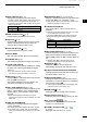
■ Screen
This Display example is
set to Wide in the “PPI
Area” item of the Display
menu.
q SCREEN RANGE READOUT (p. 17)
Displays the range of the current screen.
Indicator Description
NM nautical miles
km kilometers
L The distance unit can be selected in the Initial menu.
w FIXED RING RANGE READOUT (p. 17)
Displays the interval range of the xed ring.
e MODE INDICATOR (p. 7)
Displays the mode of the display.
Push [MODE•ZOOM]/ [ • ] to select.
Indicator Description
H-UP Head-up
C-UP Course-up
N-UP North-up
TM True Motion
L N-UP and C-UP screens require external bearing data.
L The TM screen requires bearing data and position
data.
r HEADING INDICATOR (p. 15)
Displays the heading readout. The HDG readout
indicates the bow of the ship’s heading in a
clockwise direction from north.
Indicator Description
HDG
Displayed when the “Bearing Input” in
the Initial menu is set to “NMEA,” “N+1,”
or “AUX.”
COG
Displayed When the “Bearing Input”
item in the Initial menu is set to “GPS”
or “GPS-L.”
t BEARING REFERENCE (p. 15)
Displays the bearing reference.
Indicator Description
T True bearing
M Magnetic bearing
y TUNING MODE INDICATOR (p. 9)
Displays the tuning mode and the tuning level.
Indicator Description
Auto Auto tuning
Manual Manual tuning
• “TUNE (AUTO)” is displayed when the “TUNE” item
in the Video menu is set to “Auto” or “TUNE (MAN)” is
displayed when the “TUNE” item is set “Manual.”
u REFERENCE INDICATOR (p. 15)
Displays the basis of vector reference.
q t yw e r
!4
!3
!2
!1
!0
o
u
!5
!6
@0
@2
@3
@5
@6
@1
i
!7
!9
!8
@7
@4
MR-1010RII / Page 13-8