
Instruction Manual


4
1
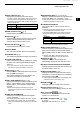
PANEL DESCRIPTION
i TRAILS INDICATOR (p. 12)
Displays the trail reference and the trail time.
• The echo remains, with gradation, during the period of
trail time on the screen. (Except for the trail time: ∞)
• Progressing time counter starts counting until the timer
reaches the trail time.
Indicator Description
T True
M Magnetic
o RAIN CONTROL ICON (p. 9)
Displayed when the RAIN function is used.
!0 SEA ICON (p. 9)
Displayed when the SEA control function is used.
“AUTO” is displayed below the icon when the
automatic SEA control function is used.
!1 LONG PULSE ICON (p. 9)
Displayed when the long pulse is used.
!2 NORTH MARK
The north mark indicates the true north direction.
!3 HEADING LINE (p.16)
The heading line indicates the ships bow direction.
!4 CROSS-LINE CURSOR
Used to measure the bearing and distance, setting
the alarm zone, selecting the ARPA/AIS targets,
and so on.
L The cross-line cursor can be moved to sixteen
directions by pushing or holding a cursor pad.
!5 AIS ICON (p. 26)
Displayed when a valid VDM sentence is received
from the [NMEA1] (AIS) port.
The indicator disappears if the AIS signal is not
received for 6 minutes and 40 seconds.
!6 EBL1/ VRM1 READOUTS (pp. 17–20)
Displays the bearing of the Electronic Bearing Line
(EBL) 1 and the distance of the Variable Range
Marker (VRM) 1, when the EBL1 and the VRM1
are used.
L Nautical miles (NM) or kilometers (km) can be
selected in the Initial menu as the distance unit in the
Initial menu.
!7 OWN SHIP INFORMATION
Displays your own ship’s latitude and longitude,
course, and speed.
L To display the position, NMEA 0183 data is required.
L The speed unit in nautical miles (kn) or kilometers
(km/h) can be selected as the speed unit in the Initial
menu.
!8 INFORMATION BOX (pp. 14, 23, 26, 32)
Displays a detailed information of a selected target,
such as AIS, ARPA, TLL, Waypoint, or, DSC.
L Refer to each section in this manual for details on the
displayed information in each function.
!9 CURSOR INFORMATION
The current position of the cross-line cursor is
displayed.
L Latitude and longitude (Lat/Lon) or Time to go (TTG)
can be selected as the position format.
L An external NMEA data in 0183 format is required.
• Displays the bearing and distance to the cross-line
cursor.
Indicator
Description
R Relative bearing
T True bearing
M Magnetic bearing
L Bearing data and position data are required.
@0 EBL2/ VRM2 READOUTS (pp. 17–20)
Displays the bearing of the Electronic Bearing Line
(EBL) 2 and the distance of the Variable Range
Marker (VRM) 2 when the EBL2 and the VRM2 are
set.
L Nautical miles (NM) or kilometers (km) can be
selected as the distance unit in the Initial menu.
@1 ARPA ICON (p. 23)
Displayed when one or more targets are
automatically acquired by auto acquire function.
@2 PLAIN POSITION INDICATOR SCOPE AREA
Displays the radar picture and plots the data such
as vessels, bases, and so on.
@3 FIXED RANGE RINGS (p. 25)
Displays the distance at xed intervals from the
own position. The interval distance is indicated by
the ring range readout (w).
L These rings are displayed when the “Ring Brill” item
in the Color menu is set to ON (1 to 3).
@4 ZOOM ICON (p. 10)
Displayed when the zoomed view is activated.
@5 ECHO STRETCH ICON (p. 11)
Displayed when the echo stretch function is used.
@6 IR1 / IR2 ICONS / (p. 10)
Displayed when the Interference Rejection (IR)
function 1 or 2 is turned ON.
@7 ALARM1 / ALARM2 ICONS /
(p.
21–22)
Displayed when the alarm 1 or 2 is set.
1
2
3
4
5
6
7
8
9
10
11
12
13
14
15
16
17
18
19
20
21
MR-1010RII / Page 13-9