!IC-M402A_SA.qxd 03.11.
!IC-M402A_SA.qxd 03.11.11 2:51 PM Page i (1,1) New2001 FOREWORD IMPORTANT Thank you for purchasing this Icom product. The IC-M402A/M402SA VHF MARINE TRANSCEIVERS are designed and built with Icom’s state of the art technology and craftsmanship. With proper care, this product should provide you with years of trouble-free operation.
!IC-M402A_SA.qxd 03.11.11 2:51 PM Page ii (1,1) New2001 IN CASE OF EMERGENCY NOTE If your vessel requires assistance, contact other vessels and the Coast Guard by sending a distress call on Channel 16. A WARNING STICKER is supplied with the transceiver. To comply with FCC regulations, this sticker must be affixed in such a location as to be readily seen from the operating controls of the radio as in the diagram below. Make sure the chosen location is clean and dry before applying the sticker. (p.
!IC-M402A_SA.qxd 03.11.11 2:51 PM Page iii (1,1) New2001 RADIO OPERATOR WARNING Icom requires the radio operator to meet the FCC Requirements for Radio Frequency Exposure. An omnidirectional antenna with gain not greater than 9 dBi must be mounted a minimum W ARN ING of 5 meters (measured from the lowest point of the antenna) vertically above the main deck and all possible personnel. This is the minimum safe separation distance estimated to meet all RF exposure compliance requirements.
!IC-M402A_SA.qxd 03.11.
!IC-M402A_SA.qxd 03.11.11 2:51 PM Page v (1,1) New2001 PRECAUTION RWARNING! NEVER connect the transceiver to an AC BE CAREFUL! The transceiver rear panel will become outlet. This may pose a fire hazard or result in an electric shock. hot when operating continuously for long periods. Place the transceiver in a secure place to avoid inadvertent use by children. CAUTION: Changes or modifications to this device, not expressly approved by Icom Inc.
!IC-M402A_SA.qxd 03.11.11 2:51 PM Page 1 (1,1) OPERATING RULES D PRIORITIES • Read all rules and regulations pertaining to priorities and keep an up-to-date copy handy. Safety and distress calls take priority over all others. • You must monitor Channel 16 when you are not operating on another channel. • False or fraudulent distress signals are prohibited and punishable by law. D PRIVACY • Information overheard but not intended for you cannot lawfully be used in any way.
!IC-M402A_SA.qxd 03.11.11 2:51 PM Page 2 (1,1) New2001 2 PANEL DESCRIPTION ■ Front panel Speaker i q Function display u y t r w e q DISTRESS KEY [DISTRESS] Transmits Distress call when pushed for 5 sec. (p. 17) w POWER/VOLUME CONTROL [VOL] Turns power ON and OFF and adjusts the audio level. (p. 8) e SQUELCH CONTROL [SQL] Sets the squelch threshold level. (p. 8) 2 r SCAN KEY [SCAN•TAG] (p. 13) ➥ Starts and stops Normal or Priority scan.
!IC-M402A_SA.qxd 03.11.11 2:51 PM Page 3 (1,1) New2001 PANEL DESCRIPTION Y]/[Z Z]•[U/I/C] u CHANNEL UP/DOWN KEYS [Y ➥ Selects the operating channels, Set mode settings, etc. (pgs. 6, 7, 30) ➥ While pushing [SCAN•TAG], push [Y] or [Z] to adjust the brightness of the LCD and key backlight. (p. 10) ➥ Selects one of three channel groups in sequence when both keys are pushed. (p. 7) 2 2 • International, U.S.A. and Canadian channels are available.
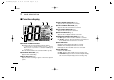
!IC-M402A_SA.qxd 03.11.11 2:51 PM Page 4 (1,1) New2001 2 PANEL DESCRIPTION ■ Function display q w r TAG CHANNEL INDICATOR (p. 13) Appears when a tag channel is selected. e r t y u i o !0 !2 !1 q CHANNEL NUMBER READOUT ➥ Indicates the selected operating channel number. • “ ” appears when a simplex channel is selected. “ ” appears when a receive only channel for a Canadian channel group is selected. (p. 7) ➥ In Set mode, indicates the selected condition. (p. 30) w TRANSMIT INDICATOR (p.
!IC-M402A_SA.qxd 03.11.11 2:51 PM Page 5 (1,1) New2001 PANEL DESCRIPTION 2 ■ Microphone !1 CHANNEL COMMENT INDICATOR ➥ Channel comment appears if programmed. (p. 10) ➥“ ” scrolls when the battery voltage drops to approx. 10 V DC or below. ➥ “ ” blinks during Dualwatch; “ ” blinks during Triwatch. (p. 11) !2 CHANNEL GROUP INDICATOR (p. 7) Indicates whether a U.S.A. “U,” International “I” or Canadian “C” channel is in use.
!IC-M402A_SA.qxd 03.11.11 2:51 PM Page 6 (1,1) New2001 3 BASIC OPERATION ■ Channel selection ï Channel 16 ï Channel 9 (Call channel) Channel 16 is the distress and safety channel. It is used for establishing initial contact with another station and for emergency communications. Channel 16 is monitored during both Dualwatch and Tri-watch. While standing by, you must monitor Channel 16. Each regular channel group has a separate leisure-use call channel. The call channel is monitored during Tri-watch.
!IC-M402A_SA.qxd 03.11.11 2:51 PM Page 7 (1,1) New2001 BASIC OPERATION 3 ï U.S.A.,Canadian and international channels ï Weather channels The IC-M402A/M402SA are preprogrammed with 57 U.S.A., 61 Canadian and 57 international channels. These channel groups may be specified for the operating area. The IC-M402A/M402SA has 10 weather channels. These are used for monitoring broadcasts from NOAA (National Oceanographic and Atmospheric Administration.
!IC-M402A_SA.qxd 03.11.11 2:51 PM Page 8 (1,1) New2001 3 BASIC OPERATION ■ Receiving and transmitting CAUTION: Transmitting without an antenna may damage the transceiver. q Rotate [VOL] to turn power ON. w Set the audio and squelch levels. ➥ Rotate [SQL] fully counterclockwise in advance. ➥ Rotate [VOL] to adjust the audio output level. ➥ Rotate [SQL] clockwise until the noise disappears. e To change the channel group, push both [Y] and [Z] on the transceiver. (p.
!IC-M402A_SA.qxd 03.11.11 2:51 PM Page 9 (1,1) New2001 BASIC OPERATION 3 ■ Call channel programming Call channel is used to select Channel 9 (default), however, you can program the call channel with your most often-used channels in each channel group for quick recall. q Push both [Y] and [Z] on the transceiver one or more times to select the desired channel group (U.S.A., International or Canada) to be programmed. w Push [16•9] for 1 sec. to select the call channel of the selected channel group.
!IC-M402A_SA.qxd 03.11.11 2:51 PM Page 10 (1,1) New2001 3 BASIC OPERATION ■ Channel comments ■ Microphone lock function Memory channels can be labeled with alphanumeric comments of up to 10 characters each for easy channel recognition. More than 6 characters comment scrolls automatically at the channel comment indicator after the channel selection. The microphone lock function electrically locks [Y]/[Z] and [HI/LO] keys on the supplied microphone.
!IC-M402A_SA.qxd 03.11.11 2:51 PM Page 11 (1,1) DUALWATCH/TRI-WATCH 4 ■ Description ■ Operation Dualwatch monitors Channel 16 while you are receiving another channel; Tri-watch monitors Channel 16 and the call channel while receiving another channel. Dualwatch/Tri-watch are convenient for monitor Channel 16 when you are operating on another channel. q Select Dualwatch or Tri-watch in Set mode. (p. 31) w Select the desired operating channel. e Push [CH/WX•DUAL] for 1 sec.
!IC-M402A_SA.qxd 03.11.11 2:51 PM Page 12 (1,1) New2001 5 SCAN OPERATION ■ Scan types Scanning is an efficient way to locate signals quickly over a wide frequency range. The transceiver has Priority scan and Normal scan. When the weather alert function is turned ON, the previously selected (used) weather channel is also checked while scanning. (p. 31) PRIORITY SCAN CH 01 CH 02 CH 16 CH 05 CH 03 CH 04 Priority scan searches through all tag channels in sequence while monitoring Channel 16.
!IC-M402A_SA.qxd 03.11.11 2:51 PM Page 13 (1,1) New2001 SCAN OPERATION 5 ■ Setting tag channels ■ Starting a scan For more efficient scanning, add desired channels as tag channels or clear the tag for unwanted channels. Channels are not tagged will be skipped during scanning. Tag channels can be assigned to each channel group (USA, INT, CAN) independently. Set scan type (Priority or Normal) and scan resume timer in advance, using Set mode. (p.
!IC-M402A_SA.qxd 03.11.11 2:51 PM Page 14 (1,1) New2001 6 DSC OPERATION ■ MMSI code programming ■ MMSI code check The 9-digit MMSI (Maritime Mobile Service Identity: DSC self ID) code can be programmed at power ON. The 9-digit MMSI (DSC self ID) code can be checked. This function is not available when the MMSI code has been programmed by the dealer. This code programming can be performed only twice. q Push [DSC•IC] to enter the DSC menu. w Push [Y] or [Z] to select “ ” and push [DSC•IC].
!IC-M402A_SA.qxd 03.11.11 2:51 PM Page 15 (1,1) New2001 DSC OPERATION 6 ■ DSC individual ID A total of 30 DSC address IDs (9-digit) can be programmed and named with up to 5 characters. D Programming Address ID/Group ID q Push [DSC•IC] to enter the DSC menu. w Push [Y] or [Z] to select “ ,” and push [DSC•IC]. r Push [Y] or [Z] to input 9-digit of the appropriate Individual/Group ID. • Push [SCAN•TAG] or [CH/WX•DUAL] to move the cursor forward or backward, respectively.
!IC-M402A_SA.qxd 03.11.11 2:51 PM Page 16 (1,1) New2001 6 DSC OPERATION D Deleting Address ID/Group ID q Push [DSC•IC] to enter the DSC menu. w Push [Y] or [Z] to select “ ” and push [DSC•IC]. ”, then push [DSC•IC]. • When no address ID is programmed, “ When a GPS receiver (NMEA0183 ver. 2.0 or 3.01) is connected, the transceiver indicates the current position data in seconds of accuracy. A NMEA0183 ver. 2.0 or 3.01 (sentence formatters RMC, GGA, GNS, GLL) compatible GPS receiver is required.
!IC-M402A_SA.qxd 03.11.11 2:51 PM Page 17 (1,1) New2001 DSC OPERATION 6 ■ Distress call A Distress call should be transmitted, if in the opinion of the Master, the ship or a person is in distress and requires immediate assistance. NEVER USE THE DISTRESS CALL WHEN YOUR SHIP OR A PERSON IS NOT IN AN EMERGENCY. A DISTRESS CALL CAN BE USED ONLY WHEN IMMEDIATE HELP IS NEEDED. q Confirm no Distress call is being received. w While lifting up the key cover, push [DISTRESS] for 5 sec.
!IC-M402A_SA.qxd 03.11.11 2:51 PM Page 18 (1,1) New2001 6 DSC OPERATION ■ Transmitting DSC calls D Transmitting Individual call The Individual call function allows you to transmit a DSC signal to a specific ship only. e Push [Y] or [Z] to specify the desired intership channel, and push [DSC•IC]. • Channel 70 is selected and “ ” appears. q Push [DSC•IC] to enter the DSC menu. •“ ” scrolls at the channel comment indicator.
!IC-M402A_SA.qxd 03.11.11 2:51 PM Page 19 (1,1) New2001 6 DSC OPERATION t After transmitting the Individual call, stands by on Channel 70 until an acknowledgement is received. •“ ” scrolls at the channel comment indicator. D Transmitting Individual acknowledgement Transmit an acknowledgement (‘able to comply’ or ‘unable to comply’) when an Individual call for you is received. q Push [DSC•IC] to enter the DSC menu. w Push [Y] or [Z] to select “ ” and push [DSC•IC].
!IC-M402A_SA.qxd 03.11.11 2:52 PM Page 20 (1,1) New2001 6 DSC OPERATION r Push [DSC•IC] to enter selected Individual call acknowledgement. •“ ” appears at the channel comment indicator. D Transmitting Group call The Group call function allows you to transmit a DSC signal to a specific group only. q Push [DSC•IC] to enter the DSC menu. w Push [Y] or [Z] to select “ ,” and push [DSC•IC]. t Push [DSC•IC] to transmit the acknowledgement to the selected station.
!IC-M402A_SA.qxd 03.11.11 2:52 PM Page 21 (1,1) New2001 DSC OPERATION r Push [Y] or [Z] to specify the desired intership channel, and push [DSC•IC]. • Channel 70 is selected and “ 6 y After the Group call has been transmitted, the display changes to the previously specified channel. ” appears. 6 u Push and hold [PTT] to communicate your message to the responding ship. t Push [DSC•IC] to transmit the Group call. • If Channel 70 is busy, the transceiver stands by until the channel becomes clear.
!IC-M402A_SA.qxd 03.11.11 2:52 PM Page 22 (1,1) New2001 6 DSC OPERATION D Transmitting All Ships call Large ships use Channel 70 as their ‘listening channel.’ When you want to announce a message to these ships, use the ‘All Ships call’ function. r Push [DSC•IC] to transmit the All Ships call. • Routine category only is available. q Push [DSC•IC] to enter the DSC menu. w Push [Y] or [Z] to select “ .” t After the All Ships call has been transmitted, the display changes to Channel 16 automatically.
!IC-M402A_SA.qxd 03.11.11 2:52 PM Page 23 (1,1) New2001 DSC OPERATION 6 D Transmitting Position Request call Transmit a Position Request call when you want to know a specified ship’s current position, etc. r Push [DSC•IC] to enter the standby condition for Position Request call. • Channel 70 is selected and “ q Push [DSC•IC] to enter the DSC menu. w Push [Y] or [Z] to select “ [DSC•IC]. ” appears. ,” then push 6 t Push [DSC•IC] to transmit the Position Request call.
!IC-M402A_SA.qxd 03.11.11 2:52 PM Page 24 (1,1) New2001 6 DSC OPERATION D Transmitting Position Report call Transmit a Position Report call when you want to announce your own position to a specific ship and to get an answer, etc. r Push [DSC•IC] to enter the standby condition for Position Report call. • Channel 70 is selected and “ q Push [DSC•IC] to enter the DSC menu. w Push [Y] or [Z] to select “ [DSC•IC]. ” appears. ,” and push t Push [DSC•IC] to transmit the Position Report call.
!IC-M402A_SA.qxd 03.11.11 2:52 PM Page 25 (1,1) New2001 DSC OPERATION 6 ■ Receiving DSC calls D Receiving a Distress call D Receiving a Distress acknowledgement While monitoring Channel 70 and a Distress call is received: ➥ The emergency alarm sounds for 2 minutes. While monitoring Channel 70 and a Distress acknowledgement to other ship is received: ➥ The emergency alarm sounds for 2 minutes. • Push any key to stop the alarm.
!IC-M402A_SA.qxd 03.11.11 2:52 PM Page 26 (1,1) New2001 6 DSC OPERATION D Receiving an Individual call D Receiving a Group call While monitoring Channel 70 and an Individual call is received: ➥ The emergency alarm or beeps sound depending on the received category. ➥ “DSC” appears and “ ” scrolls at the channel comment indicator. While monitoring Channel 70 and a Group call is received: ➥ The emergency alarm or beeps sound depending on the received category.
!IC-M402A_SA.qxd 03.11.11 2:52 PM Page 27 (1,1) New2001 DSC OPERATION 6 D Receiving an All Ships call D Receiving a Geographical Area call While monitoring Channel 70 and an All Ships call is received: ➥ The emergency alarm sounds when the category is ‘Distress’ or ‘Urgency’; 2 beeps sound for other categories. ➥ “DSC” appears and “ ” scrolls at the channel comment indicator.
!IC-M402A_SA.qxd 03.11.11 2:52 PM Page 28 (1,1) New2001 6 DSC OPERATION D Receiving a Position Request call D Receiving a Position Report call While monitoring Channel 70 and a Position Request call is received: ➥ “DSC” appears and “ ” scrolls at the channel comment indicator. While monitoring Channel 70 and a Position Report call is received: ➥ “DSC” appears and “ ” scrolls at the channel comment indicator.
!IC-M402A_SA.qxd 03.11.11 2:52 PM Page 29 (1,1) INTERCOM OPERATION (IC-M402A only) 7 ■ Intercom operation The optional Intercom function allows you to talk to the deck from the cabin. The optional HM-127 REMOTE-CONTROL MICROPHONE is required for Intercom operation. Connect an optional HM-127 as described on pgs. 34, 57. • Transmitting is impossible during Intercom operation. • The received signal is muted during Intercom operation. q Push [DSC•IC] for 1 sec. to enter Intercom mode.
!IC-M402A_SA.qxd 03.11.11 2:52 PM Page 30 (1,1) New2001 8 SET MODE ■ Set mode programming Set mode is used to change the conditions of the transceiver’s functions: Scan type (Normal or Priority,) Scan resume timer, Weather alert, Dual/Tri-watch, DSC watch, Beep tone (transceiver,) LCD contrast and Auto ACK. Available functions may differ depending on dealer setting. D Set mode operation q Turn power OFF. w While pushing [16•9], turn power ON to enter Set mode.
!IC-M402A_SA.qxd 03.11.11 2:52 PM Page 31 (1,1) New2001 SET MODE 8 ■ SET mode items D Scan type D Weather alert The transceiver has 2 scan types: Normal scan and Priority scan. Normal scan searches all tag channels in the selected channel group. Priority scan searches all tag channels in sequence while monitoring Channel 16. A NOAA broadcast station transmits a weather alert tone before important weather information.
!IC-M402A_SA.qxd 03.11.11 2:52 PM Page 32 (1,1) New2001 8 SET MODE D DSC watch D LCD contrast DSC watch monitors Channel 70 while you are receiving another channel. If a distress signal is received on Channel 70, the transceiver monitors Channel 16 and 70 alternately until the distress signal disappears. If a signal is received on another channel, DSC watch pauses until the signal disappears. This function may not be available for some channel groups depending on dealer setting.
!IC-M402A_SA.qxd 03.11.11 2:52 PM Page 33 (1,1) CONNECTIONS AND MAINTENANCE 9 ■ Supplied accessories ■ Antenna The following accessories are supplied: Qty.
!IC-M402A_SA.qxd 03.11.11 2:52 PM Page 34 (1,1) New2001 9 CONNECTIONS AND MAINTENANCE ■ Connections q t r r GPS RECEIVER JACK Connects to a GPS receiver for position indication. • A NMEA0183 ver. 2.0 or 3.01 (sentence formatters RMC, GGA, GNS, GLL) compatible GPS receiver is required. Ask your dealer about suitable GPS receivers. RCA w e q DC POWER CONNECTOR Connects the supplied DC power cable from this connector to an external 12 V battery.
!IC-M402A_SA.qxd 03.11.11 2:52 PM Page 35 (1,1) New2001 CONNECTIONS AND MAINTENANCE 9 ■ Mounting the transceiver ■ Optional MB-92 attachment D Using the supplied mounting bracket An optional MB-92 DUST COVER is available for attaching the transceiver’s front panel to prevent the keys and knobs getting wet when the transceiver is not used. The universal mounting bracket supplied with your transceiver allows overhead or dashboard mounting.
!IC-M402A_SA.qxd 03.11.11 2:52 PM Page 36 (1,1) New2001 9 CONNECTIONS AND MAINTENANCE ■ Optional MB-69 installation An optional MB-69 FLUSH MOUNT is available for mounting the transceiver to a flat surface such as an instrument panel. e Attach the clamps on either side of the transceiver with 2 supplied bolts (5 × 8 mm). • Make sure that the clamps align parallel to the transceiver body.
!IC-M402A_SA.qxd 03.11.11 2:52 PM Page 37 (1,1) TROUBLESHOOTING PROBLEM POSSIBLE CAUSE SOLUTION 10 REF. The transceiver does • Bad connection to the power supply. not turn ON. • Check the connection to the transceiver. p. 34 No sound from speaker. • Squelch level is too high. • Volume level is too low. • Speaker has been exposed to water. • Set squelch to the threshold point. • Set [VOL] to a suitable level. • Drain water from the speaker. p. 8 p.
!IC-M402A_SA.qxd 03.11.11 2:52 PM Page 38 (1,1) New2001 11 COMMANDMIC® HM-127 OPTION (IC-M402A only) ■ Panel description The optional HM-127 remotely controls the IC-M402A and provides an optional Intercom function. D Front and side keys Top keys q w e u y t r q PTT SWITCH [PTT] (pgs. 8, 43) Push and hold to transmit; release to receive. Y]/[Z Z] w CHANNEL UP/DOWN KEYS [Y ➥ Push either key to change the operating channel, Set mode settings, etc. (pgs.
!IC-M402A_SA.qxd 03.11.11 2:52 PM Page 39 (1,1) New2001 COMMANDMIC® HM-127 r CHANNEL/DUALWATCH/TRI-WATCH KEY [CH/WX• DW U/I/C] ➥ Selects and toggles the regular channels and weather channel when pushed momentarily. (pgs. 6, 7, 42) ➥ While pushing [H/L], selects one of three channel groups in sequence when pushed. (pgs. 7, 42) • International, U.S.A. and Canadian channels are available. ➥ Starts Dualwatch or Tri-watch when pushed for 1 sec. (pgs.
!IC-M402A_SA.qxd 03.11.11 2:52 PM Page 40 (1,1) New2001 11 COMMANDMIC® HM-127 ■ Function display D Top keys q PWR TAG SCAN H/L !6 !5 e w q POWER KEY [PWR] (pgs. 8, 43) Push for 2 sec. to turn the HM-127 power ON or OFF when the IC-M402A power is turned ON. w SCAN KEY [SCAN• TAG ] (pgs. 13, 46) ➥ Starts and stops Normal or Priority scan when tag channels are programmed. ➥ Push [SCAN• TAG ] for 1 sec. to set the displayed channel as a tag (scanned) channel. ➥ While pushing [H/L], push for 3 sec.
!IC-M402A_SA.qxd 03.11.11 2:52 PM Page 41 (1,1) New2001 COMMANDMIC® HM-127 11 r VOLUME INDICATOR (p. 43) Appears while audio output level is adjusted. o DUAL/TRI-WATCH INDICATOR (pgs. 11, 45) “DUAL” appears during Dualwatch; “TRI” during Tri-watch. t SQUELCH INDICATOR (p. 43) Appears while noise squelch level is adjusted. !0 WEATHER CHANNEL INDICATOR (pgs. 7, 42) ➥ “WX” appears when a weather channel is selected.
!IC-M402A_SA.qxd 03.11.11 2:52 PM Page 42 (1,1) New2001 11 COMMANDMIC® HM-127 ■ Channel selection D Channel 16 D U.S.A., International and Canadian channels q Push [16] to select Channel 16. w Push [CH/WX] to return to the condition before selecting ChanY] or [Z Z] to senel 16, or push [Y lect an operating channel. q Push [CH/WX• DW U/I/C] to select a regular channel. • Push [CH/WX• DW U/I/C] again, if a weather channel appears.
!IC-M402A_SA.qxd 03.11.11 2:52 PM Page 43 (1,1) New2001 COMMANDMIC® HM-127 11 ■ Receiving and transmitting q Push [PWR] for 2 sec. to turn power ON. Y]/[Z Z] to adjust audio output level. w Push [VOL], then [Y Y]/[Z Z] to mute any audio noise, if nec• Push [SQL], then push [Y essary. Y]/[Z Z] to select the desired channel. e Push [Y • When receiving a signal, “ ” appears and audio is emitted from the speaker. • Further adjustment of the audio level may be necessary at this point.
!IC-M402A_SA.qxd 03.11.11 2:52 PM Page 44 (1,1) New2001 11 COMMANDMIC® HM-127 ■ Call channel programming ■ Lock functions q Push [CH/WX• DW U/I/C] several times while pushing [H/L] to select the desired channel group (USA, INT, CAN) to be programmed. The Lock function electronically locks keys and switches to prevent accidental changes and function access from the microphone. w Push [16•9] for 1 sec. to select call channel of the selected channel group. • “CALL” and call channel number appear.
!IC-M402A_SA.qxd 03.11.11 2:52 PM Page 45 (1,1) New2001 COMMANDMIC® HM-127 11 ■ Display backlighting ■ Dualwatch/Tri-watch operation The function display and keys can be backlit for better visibility under low light conditions. The backlighting condition can also be adjusted independently from the transceiver. Y] or [Z Z] to select the desired channel. q Push [Y • Push [CH/WX• DW U/I/C] several times while pushing [H/L] to q Push [VOL• DIM ] for 1 sec. to enter Backlight adjusting mode.
!IC-M402A_SA.qxd 03.11.11 2:52 PM Page 46 (1,1) New2001 11 COMMANDMIC® HM-127 ■ Setting tag channels ■ Starting a scan q While pushing [H/L], push [CH/WX• DW U/I/C] several times to select the channel group (USA, INT, CAN), if desired. Y] or [Z Z] to select the desired channel to set as a w Push [Y tag channel. e Push [SCAN• TAG ] for 1 sec. to set the displayed channel as a tag channel.
!IC-M402A_SA.qxd 03.11.11 2:52 PM Page 47 (1,1) New2001 COMMANDMIC® HM-127 11 ■ Set mode programming Set mode is used to change the condition of the transceiver’s functions and the microphone’s own functions: Transceiver’s functions— scan mode (Normal or Priority,) scan resume timer, Weather alert, Dualwatch/Tri-watch, DSC watch, transceiver’s beep tone, LCD contrast (transceiver) and automatic acknowledgement. Microphone’s own functions— beep tone function (microphone) and LCD contrast (microphone.
!IC-M402A_SA.qxd 03.11.11 2:52 PM Page 48 (1,1) New2001 11 COMMANDMIC® HM-127 ■ Intercom operation ■ Channel comments q Push [LO/DX• IC SCR] for 1 sec. to activate the Intercom function. Y] or [Z Z] to select a channel to program a channel q Push [Y comment. • “IC” appears in the priority channel readout. • The channel comment disappears. • Push [CH/WX• DW U/I/C] several times while pushing [H/L] to select the channel group (USA, INT, CAN), if desired.
!IC-M402A_SA.qxd 03.11.11 2:52 PM Page 49 (1,1) New2001 COMMANDMIC® HM-127 11 ■ HM-127 supplied accessories Accessories included with the HM-127: Qty. q Connection cable (OPC-1000: 6 m; 20 ft) ...................... 1 w Mounting base ................................................................ 1 e Microphone hanger ........................................................ 1 r Screws (M3 × 16; tapping) .............................................
!IC-M402A_SA.qxd 03.11.11 2:52 PM Page 50 (1,1) New2001 11 COMMANDMIC® HM-127 ■ Installation The optional HM-127 can be connected to the transceiver directly, as well as via the supplied connection cable for longer distance remote operation. The connector of the connection cable can be installed into a cabinet, wall, etc., as a built-in plug.
!IC-M402A_SA.qxd 03.11.
!IC-M402A_SA.qxd 03.11.11 2:52 PM Page 52 (1,1) New2001 New2001 12 CHANNEL LIST Channel number Frequency (MHz) Channel number Frequency (MHz) Channel number Frequency (MHz) Channel number Frequency (MHz) USA INT CAN Transmit Receive USA INT CAN Transmit Receive USA INT CAN Transmit Receive USA INT CAN Transmit Receive 156.050 160.650 19A 64A 83A 156.050 156.050 20 20A 01 01 01A 02 02 156.100 160.700 03 03 156.150 160.750 03A 156.150 156.150 04 156.250 160.
!IC-M402A_SA.qxd 03.11.11 2:52 PM Page 53 (1,1) New2001 SPECIFICATIONS 13 ■ Specifications D General • Frequency coverage Transmit Receive • Mode • Channel spacing • Current drain (at 13.8 V) • Power supply requirement • Frequency stability • Dimensions (Projections not included) • Weight D Receiver : 156.025–157.425 MHz 156.050–163.275 MHz : FM (16K0G3E) DSC(16K0G2B) : 25 kHz : TX high 5.5 A max. Max. audio 1.5 A max. : 13.8 V DC : ±10 ppm (–20°C to +60°C; –4°F to +140°F) : 153(W) × 67(H) × 141.
!IC-M402A_SA.qxd 03.11.11 2:52 PM Page 54 (1,1) New2001 13 SPECIFICATIONS ■ Dimensions 51 (2) 67 (2 5 8) 141.6 (5 9 16) 137 (5 13 32) 153 (6 1 32) 54 32.1 (1 1 4) 86.
03.11.11 2:52 PM Page 55 (1,1) 14 TEMPLATE 153 (6 1 32) 139 (5 15 32) HM-127 2 (3 32) 67 (2 5 8) 24 to 27 (d) (15 16 to 11 16) 53 (2 3 32) MB-69 13 14 Unit: mm (inch) Cut here !IC-M402A_SA.
!IC-M402A_SA.qxd 03.11.
!IC-M402A_SA.qxd 03.11.11 2:52 PM Page 57 (1,1) New2001 OPTIONS 15 • MB-69 FLUSH MOUNT KIT For mounting the transceiver to a panel. • MB-92 DUST COVER For attaching to the front panel of the transceiver to protect it when not in use. • SP-5 EXTERNAL SPEAKER A large, external speaker for superior audio output. • SP-10 EXTERNAL SPEAKER A compact, external speaker. Features easy installation. • HM-127* REMOTE-CONTROL MICROPHONE External microphone-type controller. Provides optional intercom operation.
!IC-M402A_SA.qxd 03.11.11 2:52 PM Page 58 (1,1) New2001 A-6322H-1US Printed in Japan © 2003 Icom Inc.