INSTRUCTION MANUAL HF/VHF/UHF ALL MODE TRANSCEIVER i706MK™G This device complies with Part 15 of the FCC rules. Operation is subject to the following two conditions: (1) This device may not cause harmful interference, and (2) this device must accept any interference received, including interference that may cause undesired operation.
IMPORTANT Read this instruction manual carefully Save this instruction manual. This instruction before attempting to operate the transceiver. manual contains important safety and operating instructions for the IC-706MKIIG. PRECAUTIONS RWARNING HIGH VOLTAGE! NEVER attach an antenna or internal antenna connector during transmission. This may result in an electrical shock or burn. RNEVER apply AC to the [DC13.8V] socket on the transceiver rear panel. This could cause a fire or ruin the transceiver.
TABLE OF CONTENTS IMPORTANT ............................................................. PRECAUTIONS ........................................................ EXPLICIT DEFINITIONS .......................................... TABLE OF CONTENTS ............................................ UNPACKING ............................................................. i i i ii ii 1 PANEL DESCRIPTION ..................................... 1– 8 ■ Front panel ...............................................................
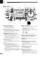
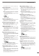
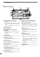
1 PANEL DESCRIPTION ■ Front panel w e AF RF/SQL i MODE i706MK™G HF/VHF/UHF TRANSCEIVER y u t r o Y BAND q USB POWER TS P.AMP/ATT RX @2 @1 S1 TUNER/CALL @0 RIT/ SUB M-CH PO SHIFT 3 5 7 9 20 40 60dB 5 10 VFO A TX !0 CH M1 SPL A/B A=B DISPLAY PHONES LOCK !9 BAND MENU !8 !7 !6 F-1 !5 F-2 !4 F-3 Z o !3 !2 !1 q POWER SWITCH [POWER] (p. 15) Turns power ON and OFF. • Push momentarily to turn power ON. • Push for 2 sec. to turn power OFF.
PANEL DESCRIPTION panel. DO NOT connect 2 microphones simultaneously. !2 LOCK SWITCH [LOCK] ➥ Push momentarily to turn the dial lock function ON and OFF. • The dial lock function electronically locks the main dial. ➥ When the optional UT-102 VOICE SYNTHESIZER UNIT is installed (p. 52), push for 2 sec. to have the frequency, etc. announced. • UT-102 operation can be adjusted in initial set mode (pgs. 53, 54). LOCK Lights while the lock function is activated. !3 DISPLAY SWITCH [DISP] (p.
1 PANEL DESCRIPTION ■ Function switches MCL D M1 FUNCTIONS M1 SPL A/B A=B MENU F-1 F-2 F-3 XFC SPLIT OPERATION (p. 29) Toggles the split function ON and OFF. SPL F-1 MEMORY CLEAR (p. 39) Clears the selected memory channel’s contents. • “}” appears. F-2 • “ä”appears when the split function is ON. • The function of [F-3] changes to XFC when the split function is ON. VFO A/B SELECTION (p. 16) ➥ Toggles between VFO A and VFO B in VFO mode.
PANEL DESCRIPTION VOX FUNCTION (p. 26) Toggles the VOX function ON and OFF. VOX F-1 • The [VOX GAIN] and [ANTI VOX] are available on the side panel. • VOX delay can be set in quick set mode (p. 48). SPEECH COMPRESSOR (p. 26) Toggles the speech compressor ON and OFF. COM F-2 • The [COMP GAIN] control is available on the side panel. AGC (p. 21) Changes the time constant of the AGC circuit.
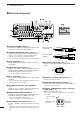
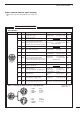
1 PANEL DESCRIPTION ■ Rear and side panels t e y r u i !2 !3 ANT 1 KEY MIC COMP GAIN w q TUNER EXT SP !1 !0 BEEP /SIDE T DC 13.8V GND ANT 2 q GROUND TERMINAL [GND] (p. 9) Connect this terminal to a ground to prevent electrical shocks, TVI, BCI and other problems. w ANTENNA CONNECTORS [ANT 1], [ANT 2] (p. 11) Accept a 50 Ω antenna with an PL-259 type plug. • [ANT 1] is for connection to an HF/50 MHz antenna. • [ANT 2] is for connection to 144 MHz antenna.
PANEL DESCRIPTION 1 !3 BEEP/SIDETONE CONTROL [BEEP/SIDETONE] Adjusts the beep tone and CW side tone audio levels. TECHNICAL INFORMATION • ACC SOCKET ACC 13 9 10 11 12 5 6 7 8 1 2 3 4 Rear panel view PIN # NAME DESCRIPTION Output voltage Output current COLOR : 8 V ±0.3 V : Less than 10 mA 1 8V Regulated 8 V output. 2 GND Connects to ground. 3 Input/output pin (HF/50 MHz). Ground level : –0.5 V to 0.8 V Goes to ground when transmitting.
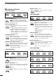
1 PANEL DESCRIPTION ■ Function display q eb !4 N W ea r w LSB USB CW R RTTY AM WFM TSQL SPL DSP ANF t NR !3 !2 NB VOX F-BK COM F AGC DUP S1 3 5 7 9 60dB VFO A 20 40 ALC VFO B 3 5 SWR PO 1 1.5 2 10 MEMO ∞ BLANK S CH M1 SPL A/B A=B y i u o !0 !1 q NARROW/WIDE FILTER INDICATORS ➥ “ã” appears when selecting AM narrow or FM narrow modes. ➥ When installing an optional narrow filter, narrow mode can be selected in CW, RTTY and SSB modes.
PANEL DESCRIPTION 1 ■ Microphone (HM-103) ➊ ➌ LOCK DN UP OFF ON ➋ ➊ UP/DOWN SWITCHES [UP]/[DN] ➋ LOCK SWITCH [LOCK] Change the operating frequency. Locks the [UP]/[DN] switches. • Push and hold to change the frequency continuously. • Tuning step is 50 Hz when no TS indicator appears. ➌ PTT SWITCH [PTT] Push and hold to transmit; release to receive. TECHNICAL INFORMATION PIN NO.
2 INSTALLATION AND CONNECTIONS ■ Unpacking After unpacking, immediately report any damage to the delivering carrier or dealer. Keep the shipping cartons. For a description and a diagram of accessory equipment included with the IC-706MKIIG, see UNPACKING on p. ii of this manual. ■ Grounding To prevent electrical shock, television interference (TVI), broadcast interference (BCI) and other problems, ground the transceiver through the GROUND terminal on the rear panel.
INSTALLATION AND CONNECTIONS 2 ■ Installation D Single body mounting MB-62 (optional) D Stand To raise the stand: With the transceiver upside down, pull the stand towards the rear panel and then upwards, as illustrated below. Supplied with the MB-62* then up Pull back *CAUTION: Non-supplied screws (longer than 8 mm) may damage the internal units. D Front panel separation ➀ While pulling the panel release button towards you, slide the front panel to the right (fig. 1).
2 INSTALLATION AND CONNECTIONS ■ Required connections AF RF/SQL MODE i706MK™G HF/VHF/UHF TRANSCEIVER Y BAND TS POWER P.AMP/ATT RX TUNER/CALL TX RIT/ SUB M-CH DISPLAY SHIFT PHONES LOCK BAND MENU HF/50 MHz ANTENNA F-1 F-2 F-3 Z MICROPHONE (p. 8) 2 m ANTENNA RTTY TERMINAL UNIT (p. 35) HM-103 ANT 1 CW KEY (p. 33) MIC TUNER EXT SP KEY DC 1 3 . 8 V GND ANT 2 PS-85 GROUND (p. 9) Use the heaviest gauge wire or strap available and make the connection as short as possible.
INSTALLATION AND CONNECTIONS 2 ■ Advanced connections AF RF/SQL HF/VHF/UHF TRANSCEIVER MODE i706MK™G Y BAND TS POWER P.AMP/ATT RX TUNER/CALL HEADPHONES TX RIT/ SUB M-CH DISPLAY SHIFT PHONES LOCK BAND MENU F-1 F-2 F-3 Z OPC-589 (p. 65) or REMOTE (p. 45) Used for computer control and transceive. SPEAKER Selectable with the [PHONE/SPEAKER] switch on the back of the front panel. ACC SOCKET (p. 6) COAX ANTENNA SWITCH DATA JACK (p. 37) 6-pin mini DIN jack to connect to a TNC, etc.
2 INSTALLATION AND CONNECTIONS ■ Power supply connections CAUTION: Before connecting the DC power cable, check the following important items. Make sure: • The [POWER] switch is OFF. • Output voltage of the power source is 12–15 V when you use a non-Icom power supply. • DC power cable polarity is correct. Red : positive (+) terminal Black : negative (–) terminal Use the optional PS-85 DC POWER SUPPLY when operating the IC-706MKIIG with AC power. Refer to the diagram below for connection.
INSTALLATION AND CONNECTIONS 2 ■ External antenna tuners and linear amplifier CONNECTING THE AH-4 The AH-4 can be used for the HF bands and 50 MHz band only.
3 FREQUENCY SETTING ■ When first applying power (CPU resetting) Before first applying power, make sure all connections required for your system are complete by referring to section 2. Then, reset the transceiver using the following procedure. [POWER] [Y] Note: Resetting clears all programmed contents in memory channels and returns all initial set mode and quick set mode contents to their default values. [Z] USB ➀ Make sure the transceiver power is OFF.
FREQUENCY SETTING ■ VFO description 3 frequency and operating mode for operation. VFO is an abbreviation of Variable Frequency Oscillator, and traditionally refers to an oscillator. The IC-706MKIIG’s VFO can store a frequency and an operating mode. You can call up a desired frequency to a VFO with the memo pad-read switch (p. 42) or with the memory transfer switch (p. 42).
3 FREQUENCY SETTING ■ Frequency setting • Band selection All HF ham bands, the 50 MHz band, the 144 MHz band and a general coverage receiver band are included in the IC-706MKIIG. FM LSB Z USB Push [(Y)BAND]/[(Z)BAND] to select the desired band. • Pushing [(Y)BAND]/[(Z)BAND] continuously scrolls through the available bands. Note: The band stacking register can also be used to select bands. Refer to p. 19.
FREQUENCY SETTING 3 • 1 MHz quick tuning step The quick tuning step function allows you to change the frequency in 1 MHz steps when rotating the main dial. This function is only available in FM, WFM and AM modes. ➀ Select FM, WFM or AM mode if necessary. ➁ Push [TS] momentarily to toggle between the 1 Quick tuning step indicator FM MHz tuning step and the programmable tuning step. • “Z” appears above the 1 MHz indicator when the 1 MHz tuning step is selected.
3 FREQUENCY SETTING • Quick band change function The quick band change function automatically stores the last frequency and mode used for each band in a band stacking register. This is convenient for contest operation, etc. The tables below show the quick band change default settings for each band. USB ➀ Select S3. • Push [DISPLAY] when M or G is displayed. • Push [MENU] twice to select S3. S1 ➁ Push [F-1]–[F-3] to select a band stacking register.
4 RECEIVE AND TRANSMIT ■ Functions for receive D IF shift function The IF shift function electronically changes the passband frequency of the IF (intermediate frequency) and cuts out higher or lower frequency components of the IF to reject interference. The function shifts the IF frequency up to ±1.2 kHz in 15 Hz steps in SSB/CW/RTTY modes and up to ±250 Hz in 3 Hz steps in CW-ã/RTTY-ã modes. The IF shift is not available in FM and AM modes.
4 RECEIVE AND TRANSMIT D Noise blanker The noise blanker reduces pulse-type noise such as that generated by automobile ignition systems. This function is not effective for FM modes or for non pulsetype noise. If you don’t want to use the noise blanker for AM communications, the “AM noise blanker” item in Initial Set mode must be turned OFF (ON is the default setting—p. 53). ➁ Push [(F-2)NB] to toggle the noise blanker ON and OFF. • “NB” appears when the noise blanker is turned ON. USB NB ➀ Select M3.
RECEIVE AND TRANSMIT 4 D RF gain and squelch The IC-706MKIIG uses the same control, [RF/SQL], to adjust one of either the RF gain or the squelch. [RF/SQL] adjusts either the RF gain or the squelch depending on the operating mode selected and the condition of the RF gain item in initial set mode (p. 51; also see the table at right). The RF (Radio Frequency) gain is used to adjust the receiver gain. • This control should be set to the 11 o’clock position for normal use.
4 RECEIVE AND TRANSMIT D Optional filter selection Two optional filters can be installed in the IC706MKIIG. ➀ Select M3. Narrow filters help reject interference from adjacent signals and obtain good selectivity. • Push [DISPLAY] 1 or 2 times if G or S appears. • Push [MENU] one or more times to select M3. ➁ Push [(F-1)FIL] momentarily to select the narrow Wide filters provide improved audio for SSB operation when no interfering signals are present.
RECEIVE AND TRANSMIT 4 ■ DSP Functions (may require an optional unit depending on version—see p. 61) D ANF (Automatic Notch Filter) function This function automatically attenuates beat tones, tuning signals, etc., even if they are moving. The automatic notch filter functions in SSB, FM and AM modes. ➀ Select S4 (DSP menu). • Push [DISPLAY] 1 or 2 times when M or G is displayed. • Push [MENU] one or more times to select S4. ➁ Push [(F-1)ANF] to toggle the automatic notch filter ON and OFF.
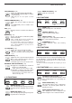
4 RECEIVE AND TRANSMIT ■ Functions for transmit D Output power and mic gain • Setting output power ➀ Push [DISPLAY] for 2 sec. to select quick set mode. ➁ Push [MENU] one or more times to select Q1 RF Maximum output power is selected. USB POWER. ➂ Rotate the main dial to select the desired output. • Output power is displayed in 11 steps (L, 1–9 and H) but is continuously selectable. S1 3 5 7 9 PO 20 40 5 60dB 10 Q1 RF POWER ➃ Push [DISPLAY] to exit quick set mode.
RECEIVE AND TRANSMIT 4 D Speech compressor The IC-706MKIIG has a built-in, low distortion speech compressor circuit. This circuit increases your average talk power in SSB mode and is especially useful for DX’ing when the receiving station is having difficulty copying your signal. ➀ Select USB or LSB mode. ➁ Select the ALC meter. • Push [DISPLAY] 1 or 2 times to select M, if necessary. • Push [MENU] one or more times to select M3, then push [(F-3)MET] one or more times to select “ALC.
4 RECEIVE AND TRANSMIT D Optional AT-180 AUTOMATIC ANTENNA TUNER operation The AT-180 automatic antenna tuner matches the IC706MKIIG to the connected antenna automatically. Once the tuner matches an antenna, the variable capacitor angles are memorized as a preset point for each frequency range (100 kHz steps). Therefore, when you change the frequency range, the variable capacitors are automatically preset to the memorized point. CAUTION: NEVER transmit with the tuner ON when no antenna is connected.
RECEIVE AND TRANSMIT 4 D Optional AH-4 AUTOMATIC ANTENNA TUNER operation The AH-4 matches the IC-706MKIIG to a long wire antenna more than 7 m/23 ft long (3.5 MHz and above). • See p. 14 for connection. • See the AH-4 instruction manual for AH-4 installation and antenna connection details. AH-4 operation Tuning is required for each frequency. Be sure to re-tune the antenna before transmitting when you change the frequency—even slightly. ➀ Set the desired frequency in an HF band.
4 RECEIVE AND TRANSMIT ■ Split frequency operation Split frequency operation allows you to transmit and receive on two different frequencies. Split frequency operation uses 2 frequencies, one in VFO A and the other in VFO B. Following is an example of setting 7.057 MHz, CW mode in VFO A (for receive) and 7.025 MHz, CW mode in VFO B (for transmit). ➀ Select VFO A and set the frequency to 7.057 MHz/CW. • [(F-2)A/B] is available when M1 appears. • [(F-3)V/M] is available when M2 appears.
RECEIVE AND TRANSMIT 4 D Repeater operation A repeater amplifies received signals and retransmits them at a different frequency. When using a repeater, the transmit frequency is shifted from the receive frequency by an offset frequency. A repeater can be accessed using split frequency operation with the shift frequency set to the repeater’s offset frequency. ➀ Set the offset frequency and turn ON the quick split Turn the quick split function ON. (Initial set mode default is ON.
4 RECEIVE AND TRANSMIT ■ Tone squelch operation Tone squelch operation is a method of communications using selective calling. Only received signals having a matching tone will open the squelch. Before communicating using tone squelch, all members of your party must agree on the tone squelch frequency to use. ➀ Push [MODE] one or more times to select FM mode. ➁ Push and hold [DISPLAY] to enter Quick Set mode. ➂ Push [MENU] one or more times to select item Q7 Set the tone frequency (quick set mode).
RECEIVE AND TRANSMIT 4 ■ One-touch repeater function This function allows you to set repeater operation with the push of one switch. ➀ Push [(Y)BAND]/[(Z)BAND] to select the 28 MHz band. ➁ Rotate [DIAL] to select the operating frequency. ➂ Push [MODE] one or more times to select FM. ➃ Select M4 and turn the one-touch repeater function ON. ➥ Push and hold [(F-2)DUP] to toggle the onetouch repeater function ON and OFF.
4 RECEIVE AND TRANSMIT ■ Functions for CW D Connections for CW Rear panel Quick set mode setting CW CW [ACC] [ELEC KEY] For no break-in operation: Connect an external switch such as a foot switch; or use the RTTY SEND terminal for all bands. 12 (See p. 35.) 13 9 10 11 5 6 7 8 1 2 3 4 Paddle CW 144/430 MHz CW HF/50 MHz Straight key CW See p. 34 for connection details: Paddle operation from front panel MIC connector.
RECEIVE AND TRANSMIT D CW pitch control 4 QUICK SET MODE The received CW audio pitch and monitored CW audio pitch can be adjusted to suit your preferences (300 to 900 Hz) without changing the operating frequency. ➂ Rotate the main dial to set the desired pitch. ➃ Push [DISPLAY] to exit quick set mode. This shows the default setting for the CW pitch control (600 Hz). CW ➀ Push [MODE] one or more times to select CW mode. ➁ Select CW PITCH in quick set mode. • Push [DISP] for 2 sec.
4 RECEIVE AND TRANSMIT ■ Functions for RTTY D Connections for RTTY (FSK) [EXT SP] [RTTY] [ACC] Rear panel 2-conductor 1/8˝ plug TU or TNC Personal computer AF GND SEND FSKK GND 3-conductor 1/8˝ plug (supplied) Use either the ACC or one of the two 1/8˝ plugs Rear panel view 13 9 10 11 12 5 6 7 8 1 2 3 4 SQL*1 (light green) AF out (light blue) MSEND*2 GND (red) FSKK (black) *1Connect SQL line when required.
RECEIVE AND TRANSMIT 4 D RTTY (FSK) operation ➀ Connect a terminal unit as at left. ➁ Select RTTY (or åRTTY—see bottom of page) RTTY mode is selected. RTTY mode with [MODE]. ➂ Select the desired FSK tone/shift frequencies and keying polarity as below. ➃ Set the desired frequency with the main dial. S1 3 5 7 9 20 40 5 PO 60dB VFO A 10 CH M1 SPL A/B A=B • Use [(F-1)1/4] in the M4 display when critical setting is required. ➄ Operate the connected PC or TNC (TU).
4 RECEIVE AND TRANSMIT ■ Packet operation D Connections for packet DATA IN q PTTP e TX AUDIO GND w GND r DATA OUT y SQ t AF OUT TNC SIDE RX AUDIO SQL PTT DATA RS-232C Rear panel TU or TNC Personal computer D Data socket q w r e t y Rear panel view PIN #/NAME q DATA IN w GND e PTTP r DATA OUT t AF OUT y SQ DESCRIPTION Communication data input. Ground for DATA IN, DATA OUT and AF OUT. Transmits when grounded. Outputs 9600 bps receive data. Outputs 1200 bps receive data. Squelch output.
RECEIVE AND TRANSMIT 4 ■ SWR The IC-706MKIIG has a built-in circuit for measuring antenna SWR while in SSB mode—no external equipment or special adjustments are necessary. ☞ NOTE: The SWR of ANT1 only can be read since ANT2 has no measuring circuit. D Measuring SWR The IC-706MKIIG can measure SWR in 2 ways: (A) Spot measurement; or (B) Plot measurement. (A) Spot measurement ➀ Confirm that the output power is over 30 W. ➁ Push [MENU] one or more times to select M3.
5 MEMORY AND SCAN OPERATION ■ Memory channels The transceiver has 105 memory channels (plus 2 call channels). Memory mode is useful for quickly changing to often-used frequencies. Note: During split frequency operation, programmed memory contents can be called up to the SUB readout (dot matrix portion of the display). All 105 memory channels are tuneable which means the programmed frequency can be tuned temporarily with the main dial, etc., in memory mode.
MEMORY AND SCAN OPERATION 5 ■ Memory/call programming • Programming in VFO mode [EXAMPLE]: Programming 7.088 MHz/LSB into ch 12. ➀ Select M2 functions. CW • Push [DISPLAY] 1 or 2 times to select M. • Push [MENU] one or more times to select the M2 functions. TS VFO A MODE CH ➁ Set the desired frequency and operating mode in LSB VFO mode. • If you want to program the split frequency function, program both receive and transmit frequencies into VFO A and B, then turn ON the split function.
5 MEMORY AND SCAN OPERATION ■ Frequency transferring The frequency and operating mode can be transferred from memory mode to VFO mode. ➀ Select VFO mode with [(F-3)V/M] in the M2 dis- [EXAMPLE]: Transferring contents of memory 16. play. ➁ Select a memory channel with [M-CH]. Operating frequency: 21.320 MHz/USB (VFO) Contents of memory 16: 14.020 MHz/CW • Select memory mode to confirm the memory channel’s contents, if desired; then return to VFO mode.
MEMORY AND SCAN OPERATION 5 ■ Memo pads The transceiver has a memo pad function to store frequency and operating mode for easy write and recall. The memo pads are separate from memory channels. The default number of memo pads is 5, however, this can be increased to 10 in initial set mode if desired (p. 53).
5 MEMORY AND SCAN OPERATION ■ Scan types PROGRAMMED SCAN PRIORITY WATCH Repeatedly scans between two scan edge frequencies (scan edge memory channels 1A and 1B). Checks for signals on a memory or call channel while operating on a VFO frequency. Memory channel watch Call channel watch VFO frequency VFO frequency Scan Scan edge 1A or 1B Scan edge 1B or 1A Jump Memory channel This scan operates in VFO mode. This scan operates in VFO mode.
MEMORY AND SCAN OPERATION 5 ■ Programmed scan operation ➀ Select VFO mode. ➁ Select the desired operating mode. • The operating mode can also be changed while scanning. ➂ Set [SQL] open or closed. • See page a left for squelch condition. ➃ Select S2, then push [(F-1)SCN] to start the scan. • Decimal point blinks while scanning. USB S1 3 5 7 9 PO 20 40 5 • During scan [TS] can be used only when resume is ON.
6 REMOTE JACK (CI-V) INFORMATION D CI-V connection example 9–15 V DC The transceiver can be connected through an optional CT-17 CI-V LEVEL CONVERTER to a personal computer equipped with an RS-232C port. The Icom Communication interface-V (CI-V) controls the following functions of the transceiver. Up to four Icom CI-V transceivers or receivers can be connected to a personal computer equipped with an RS-232C port. See p. 55 for setting the CI-V condition using initial set mode.
REMOTE JACK (CI-V) INFORMATION 6 COMMAND TABLE Cn 00 01 02 03 04 05 06 07 08 09 0A 0B 0C 0D Sc — xx — — — — 00*1 01*1 02*1 03*1 04*1 05*1 06*1 — 00 01 A0 B0 — mc*2 — — — — — Description Send frequency data Send mode data Read band edge frequencies Read display frequency Read display mode Set frequency data Set LSB Set USB Set AM Set CW Set RTTY Set FM Set WFM Set to VFO Set to VFO A Set to VFO B VFO A=B Switch VFO A and B Set to memory mode Mch Memory write Memory to VFO Memory clear Read duplex offs
7 SET MODE ■ General Set mode is used for programming infrequently changed values or conditions of functions. The IC706MKIIG has 2 separate set modes: quick set mode and initial set mode. D Quick set mode operation ➀ While power is ON, push [DISPLAY] for 2 sec. • Quick set mode is selected and one of its items appears. • Quick set mode items vary depending on the operating mode (SSB, FM, etc.) selected. [POWER] Main dial [Y] ➁ Push [MENU] one or more times to select the desired item.
SET MODE 7 ■ Quick set mode items Q1 RF POWER (all modes) The default is H (maximum power). This item adjusts the RF output power. The RF output power can be adjusted from L, 1 to 9 and H for indication, however, it can be adjusted continuously. Q2 MIC GAIN Note that while adjusting the output power, the power meter is displayed automatically. (SSB/AM/FM only) The default is 5. This item adjusts microphone gain from 1 to 10 for indication, however, it can be adjusted continuously.
7 SET MODE Q4 CW PADDLE (CW only) This item adjusts the CW paddle type. Four selections are available. •n : normal (for electronic keyer use) •r : reverse (for electronic keyer use) • buG : When using the electronic key, key down produces a “dash,” releasing the key automatically produces a “dot(s).” • oFF : Turns OFF the electronic keyer (for straight key use) • ud : For using the microphone’s [UP]/[DN] keys instead of the CW paddle. Q5 ANTI VOX Q5 KEY SPEED USB The default is 5.
SET MODE Q8 RPTR-T SCN (repeater tone scan) FM The default is 88.5 Hz. During repeater operation, you can detect the tone frequency necessary to open a repeater (see p. 30). Q8 T-SQL SCN (tone squelch tone scan) 7 FM The default is 88.5 Hz. During tone squelch operation, you can detect the tone frequency necessary to communicate using tone squelch (see p. 31).
7 SET MODE 6 AUTO OFF (auto power OFF) The auto power OFF function can be used to automatically turn the transceiver OFF after a specified time of operation. This item can be set to 30 min., 60 min., 90 min., 120 min., or OFF. 7 RF/SQL Auto power OFF set to 20 min. The [RF/SQL] control functions as RF gain control only. The [RF/SQL] control functions as squelch control only. Pushing [RIT/SUB] selects the RIT function (default). Pushing [RIT/SUB] selects the sub dial function.
SET MODE 12 QUICK SPLIT (quick split function) When this item is set to ON, pushing [SPL] for 2 sec. sets the undisplayed VFO frequency to the displayed VFO frequency plus the split offset or duplex offset, and activates split operation. 13 SPLIT LOCK Quick split function OFF. Split lock function OFF (default) Split lock function ON (split offset) This item sets the offset (difference between transmit and receive frequencies) for the quick split function.
7 SET MODE 20 AUTO RPTR (auto repeater) When this item is set to “on 1”, the tone encoder is not set when the auto repeater is activated; when set to “on 2” the auto repeater function also sets the tone encoder on. 21 SCAN RESUME Scan speed is set to high (default). Scan speed is set to low. Up/down speed is set to high (default). Up/down speed is set to low. Noise blanker available (default) Noise blanker not available 5 memo pads are available (default). 10 memo pads are available.
SET MODE 27 A-TUNE STRT (auto tuner start) The optional AT-180 ANTENNA TUNER has an automatic start capability which starts tuning if the SWR is higher than 1.5–3. When “oFF” is selected, the tuner remains OFF even when the SWR is poor (1.5–3). When “on” is selected, automatic tune starts even when the tuner is turned OFF. 28 PTT TUNE 7 Auto tune function OFF (default). Auto tune function ON. Note: Even when “on” is selected, automatic tune does not start for the 50 MHz band.
7 SET MODE 33 S-LVL SPCH (S-level speech) When an optional UT-102 SPEECH SYNTHESIZER UNIT is installed, the synthesizer can be set to read out the frequency/mode only, or both the frequency/mode and S-meter level. 34 CI-V ADDRES (CI-V address) To distinguish equipment, each CI-V transceiver has its own Icom standard address in hexadecimal code. The IC-706MKIIG’s address is 4EH.
MAINTENANCE ■ Fuse replacement 8 DC POWER CABLE FUSE REPLACEMENT If a fuse blows or the transceiver stops functioning, try to find the source of the problem, and replace the damaged fuse with a new, rated fuse. Caution: Disconnect the DC power cable from the 30 A fuse transceiver when changing a fuse. The IC-706MKIIG has 2 types of fuses installed for transceiver protection. • DC power cable fuses ...................................... 30 A • Circuitry fuse ............................. F.G.M.B.
9 TROUBLESHOOTING The following chart is designed to help you correct problems which are not equipment malfunctions. POWER SUPPLY PROBLEM Power does not come on when the [POWER] switch is pushed. If you are unable to locate the cause of a problem or solve it through the use of this chart, contact your nearest Icom Dealer or Service Center. POSSIBLE CAUSE DC power connected. cable is improperly Fuse is blown. SOLUTION Reconnect the power cable correctly. REF. p.
TROUBLESHOOTING SCAN DISPLAY TRANSMIT PROBLEM POSSIBLE CAUSE SOLUTION 9 REF. Transmitting is impossible. The operating frequency is not set to a ham band. Set the frequency to a ham band. Output power is too low. Power is set to a lower power than maximum. Set the output power in quick set p. 44 mode. Microphone gain is set too low. Set microphone gain to a suitable p. 44 position using quick set mode. The antenna is not connected properly. Reconnect the antenna connector.
10 OPTIONAL INSTALLATIONS/SETTINGS ■ Opening the transceiver case To remove the transceiver case unscrew the 10 screws (5 in the top panel and 5 in the bottom panel) as shown in the diagram below. Caution: Disconnect the DC power cable from the transceiver before performing any work on the transceiver. ■ UT-102 VOICE SYNTHESIZER UNIT ➀ Remove the top cover as shown above. ➁ Connect the UT-102 as shown in the diagram at right (label side up). ➂ Replace the top cover.
OPTIONAL INSTALLATIONS/SETTINGS 10 ■ CR-282 HIGH-STABILITY CRYSTAL UNIT By installing the CR-282, the total frequency stability of the transceiver will be improved. ➀ Remove the bottom cover as shown on the oppo- CR-282 frequency stability: ±0.5 ppm (–30°C to +60°C; –22°F to +140°F) site page. ➁ Remove the 5 screws and 2 flat cables holding the PLL unit in place. ➂ Remove the existing crystal unit. ➃ Put the CR-282 in the space available as shown in the diagram.
10 OPTIONAL INSTALLATIONS/SETTINGS ■ UT-106 DSP RECEIVER UNIT D Installation ➀ Open the transceiver case as shown on p. 59. ➁ Remove the 4-pin connector (P251) from J1413 on MAIN unit the MAIN unit (top side) and plug it into J1 of the UT-106 on the PLL unit (bottom side). ➂ Plug the 4-pin connector (P1) from the UT-106 into J1413 on the MAIN unit. ➃ Plug the supplied ribbon cable into J3 on the UT106 and J253 on the PLL unit.
OPTIONAL INSTALLATIONS/SETTINGS 10 ■ AT-180 internal switch description The optional AT-180 has 3 operating conditions for HF band operation. Select a suitable condition according to your antenna system. ➀ Remove the top cover of the AT-180. ➁ Set the tuner switches to the desired positions according to the table below. SW Position Operation The tuner operating condition is set by S2 (default) described below.
11 INTERNAL VIEWS D Top view Caution: The transceiver has been thoroughly tested and adjusted at the factory before being shipped. The transceiver warranty does not cover any problems caused by unauthorized internal adjustment. The internal speaker has been removed in this diagram for illustration purposes. FILTER unit 430 MHz Tx power adj. 144 MHz Tx power adj. 50 MHz Tx power adj. HF Tx power adj. FM deviation adj. AM Tx carrier adj. ID APC adj. NB sencitivity adj.
OPTIONS IC-PW1 HF + 50 MHz 1 kW LINEAR AMPLIFIER 12 AT-180 HF/50 MHz AUTOMATIC ANTENNA TUNER Full-duty 1 kW linear amplifier including an automatic antenna tuner. Has automatic tuning and band selection capability. Full break-in (QSK) operation is possible. The amplifier/power supply unit and the remote control unit are separated. The OPC-599 is necessary to connect the IC706MKIIG to the IC-PW1.
12 OPTIONS SP-7 EXTERNAL SPEAKER SP-10 EXTERNAL SPEAKER SP-12 EXTERNAL SPEAKER SP-12 SP-10 Compact speaker for base station operation. Height can be adjusted for your convenience. • Input impedance: 8 Ω • Max. input power: 5 W External speakers suitable for mobile operation. SP-12: Slim-type; 8 Ω/3 W SP-10: Compact-type; 4 Ω/5 W Equipped with 4 types of audio filters, a headphone jack and can be connected to 2 transceivers. • Input impedance: 8 Ω • Max.
SPECIFICATIONS ■ GENERAL • Frequency coverage : Receive 30 kHz – 199.999999 MHz* 400–470.000 MHz* Transmit 1.800 – 1.99999 MHz* 3.500 – 3.9999 MHz* 7.000 – 7.300 MHz* 10.100 – 10.150 MHz 14.000 – 14.350 MHz 18.068 – 18.168 MHz 21.000 – 21.450 MHz 24.890 – 24.990 MHz 28.000 – 29.700 MHz 50.000 – 54.000 MHz* 144.000 – 148.000 MHz* 430.000 – 450.000 MHz* *Depending on version.
14 MENU GUIDE LOCK + power ON Power OFF then ON to exit initial set mode. Initial set mode MENU Y Z MENU 67 No. 1 2 3 4 5 6 7 8 9 10 11 12 13 14 15 16 17 18 Indication MODE SELECT BEEP BAND BEEP BACK LIGHT KEY LIGHT AUTO OFF RF/SQL SUB DIAL OPT.FIL 1 OPT.FIL 2 PEAK HOLD QUICK SPLIT SPLIT LOCK SPL OFFSET DUP HF DUP 50M DUP 144M DUP 430M 19 1TOUCH RPTR Description No.
MENU GUIDE M1 M2 SPL MW A/B MÜV MCL MENU A=B split XFC (when is ON) DISPLAY (in memory mode) FIL NB MET M4 VOX COM AGC (SSB/AM) M4 1/4 BRK AGC (CW) MW MPW S2 SCN PRI SEL MENU V/M M3 S1 14 MPR V/M (in memory mode) S3 7 50 144 S4 ANF NR NRL DISPLAY M4 M4 1/4 VOX AGC COM TON (RTTY) DISPLAY MENU (FM) DISPLAY DISPLAY G1 BAND scope G2 IF SHIFT G3 TX freq. G4 Memory name For 2 sec. Quick set mode No.
Count on us! A-5564H-1EX-q Printed in Japan © 1999 by Icom Inc.