2001 NEW AT-140_1.qxd 04.4.
001 NEW 2001 NEW AT-140_1.qxd 04.4.26 9:16 Page 2 FOREWORD PRECAUTIONS Thank you for purchasing the AT-140 HF AUTOMATIC ANTENNA TUNER. R DANGER HIGH VOLTAGE! NEVER touch The AT-140 is designed, primarily for use with Icom HF transceivers. the antenna terminal, ground terminal, antenna or counterpoise while transmitting. Place the AT-140, antenna and counterpoise in positions where no one can touch them. Refer to your HF transceiver instruction manual for operation.
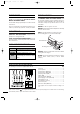
2001 NEW AT-140_1.qxd 04.4.26 9:16 Page 3 MISCELLANEOUS ITEMS TABLE OF CONTENTS The following parts are additionally required for installation, but are not supplied with the AT-140. Purchase these parts locally. FOREWORD …………………………………………… i q AWG 14×4-conductor shielded cable *Icom offers an optional OPC-1147/N CONTROL CABLE. Length: 10 m; 32.
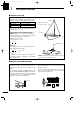
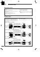
2001 NEW AT-140_1.qxd 04.4.26 9:16 1 Page 1 ANTENNA SYSTEM ■ Antenna for ship Required antenna element length Required antenna element length to achieve full performance varies according to the lowest frequency: The lowest frequency Required antenna element length 1.6 MHz band 7 m; 23.0 feet or longer 4 MHz band 3 m; 9.8 feet or longer Insulator Backstay operates as a long-wire antenna. The longer the antenna element, the better the antenna efficiency.
AT-140_1.qxd 04.4.26 9:16 Page 2 ANTENNA SYSTEM 1 ■ Coaxial cable Insulate the lead-in cable of the AT-140 antenna terminal and antenna element from other metal objects. To prevent erroneous indications, keep cables as far away as possible from the flux gate compass. To prevent interference, keep cables as far as possible from an antenna, electric pump and other electronic equipment. Use suitable noise filters for alternators, fluorescent lights, etc. Ask your Dealer for details.
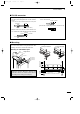
2001 NEW AT-140_1.qxd 04.4.26 9:16 2 Page 3 INSTALLATIONS ■ Installation outline q Connect a control cable and 4-conductor shielded cable. • Refer to “Control cable” below. r Connect the control cable and the coaxial between the transceiver and the AT-140. • Refer to p. 5 “Cable connections.” w Connect and solder the PL-259 connector to the coaxial cable. • Refer to p. 4 “PL-259 connector.” e Mount the AT-140 in the desired location. t Connect an antenna, ship’s ground or counterpoise.
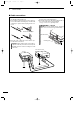
AT-140_1.qxd 04.4.26 9:16 Page 4 INSTALLATIONS 2 ■ PL-259 connector q Slide the coupling ring over the coaxial cable. Strip the cable jacket and pull back to reveal 10 mm of braid. e Slide the connector body over the cable and solder as shown below. Solder Solder • Soft solder the exposed braid and then pull out the jacket. Coupling 30 mm r Screw the coupling ring onto the connector body. 10 mm (soft solder) w Strip the cable as shown below.
2001 NEW AT-140_1.qxd 2 04.4.26 9:16 Page 5 INSTALLATIONS ■ Cable connections q Connect the coaxial cable and the control cable to the AT-140 as illustrated below. w Cover both the antenna and the control cable connectors with rubber vulcanizing tape and fix it with a vinyl tape to prevent water seeping into the connector. r Connect the coaxial cable and the control cable to the transceiver as illustrated below.
2001 NEW AT-140_1.qxd 04.4.26 9:16 Page 6 CONTROL CABLE SIGNALS 3 ■ Terminal information Consider the following points when using a non-Icom transceiver. Terminal [KEY] [13.6] [STAR] [E] Description Key voltage. Grounded during tuning. Max. current drain 100 mA. 13.6 V DC + input terminal. Max. current drain 2 A Start voltage [STAR] When a start voltage (less than 1 V) is received, the AT-140 begins automatic tuning. More than 350 msec.* Start voltage 8 [V] 6 Approx. 7.
2001 NEW AT-140_1.qxd 3 2001 NEW 04.4.26 9:16 Page 7 CONTROL CABLE SIGNALS ■ Transceiver setting IC-M700 with serial number 2500 and below In the IC-M700, change the [TUNE] switch setting from the “1” position to the “2” position. Confirm that the [KEY] switch is in the “2” position. Refer to the ICM700 instruction manual p. 9 for details. [KEY] [TUNE] Confirm “2” position. Select “2” position. Other IC-M700 and IC-M700TY Nothing necessary to set.
2001 NEW AT-140_1.qxd 04.4.26 9:16 Page 8 UNIT DESCRIPTION AND SPECIFICATIONS 4 ■ Unit description 340 mm; 13.4 in 230 mm; 9.1 in 80 mm; 3.1 in Ground terminal Mounting plate Water drain screw Antenna cable receptacle Control cable receptacle Antenna terminal Mounting plate 91.5 mm; 3.6 in ■ Specifications • Frequency coverage • Power supply requirement • Current drain • Operating temperature range • Weight • Antenna connector • Max.
2001 NEW AT-140_1.qxd 04.4.26 9:16 Page 9 Icom America Inc. Icom (Europe) GmbH 2380 116th Avenue N.E., Bellevue, WA 98004, U.S.A. Phone: +1 (425) 454-8155 Fax: +1 (425) 454-1509 URL: http//www.icomamerica.com E-mail: sales@icomamerica.com Phone: (425) 454-7619 Communication Equipment Himmelgeister Str. 100, D-40255 Düsseldorf, Germany Phone: +49 0211 346047 Fax: +49 0211 333639 URL: http//www.icomeurope.com E-mail: info@icomeurope.