FOREWORD Thank you for choosing: this COM: product: The AT:150 is ‘an HF Automatic Antenna Tuner developed by COM utilizing the latest electronics technology and precise, advanced engineering. To: fully enjoy. the benefit of this high:performance antenna tuner, please study thug instruction manual thoroughly prior 1o Operation.
SECTION 2 NATURES * RAPID TUNEUP A newly “developed detection circuit ‘determines the position of both' input and output variable ‘capacitors; plods the required “wing direction. ' Separate; powerful motors’ quickly’ ting the capacitors for & completely matched antenna Siemens, * AUTOMATIC BAND SELECTION instant band changes are possible: with an ICON HF: transceiver, * PRESET CONTROLS PROVIDED Conveniently: located controls: allow one frequency per band to be tuned: in advance.
SECTION 3 INSTALLATION UNPACKING Accessories glutted (1) Necessary cabin (1 meter), (25 Coaxial cable 11 mater). RECOMMENDATIONS FOR INSTALLATION POWER: SUPPLY Carefully “remove your: antenna’ tuner from the [packing: carton and: examine it for signs of shipping damage. Notify ‘the delivering ‘carrier “or dealer immediately, stating full ‘details; should any. damage: be ‘apparent: We recommend: you' keep:the shipping carton for shooting; moving oF reshipping: the wren I ‘necessary.
ANTS: can be: connected: by means of the front panel switch A long: wire :antenna. for general coverage reception could: be attached 10 this connector. imperial four i cases; the Antennas may “be used for ‘transmitting fiftieth: VEER s kept ot 310 of lags) Pin Na. [ Description Explanation 1 8V Reference voltage for: band:switching: 2 GND: Ground; 3 e Not used. @ie 4 BAND: Input for external band switching signal. Not used. 2l 6 et Not used: 7 138V 13.
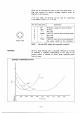
Suppose: 3. typical: transgender antenna covering MHz MHz and MHz has SWERVE values ay shown in the diagram. The:antenna appears: 10 offer: s ‘matched ‘condition: in‘the S5B portion: :of MHz and. 28MH2 as well as the CW portion of MHz, An entente tuner may not be required while operating in: these areas of ‘the bands. But, operation: in the: CW: portions of MHz ‘and 28MMz or in ‘the: SSB portions 'of MHz.
SECTION FRONT PANEL TUNE SWITCH AUTO-TUNE INDICATOR ANTS SWITCH ANT INDICATOR BAND INDICATORS WAIT INDICATOR UNCTIONS Switches the automatic tuner circuit. When the switch is pushed IN:the: TUNE indicator lights and the AT-150 -acts: as an-ate masc: antenna [tuner; . When the switch s QUT, ‘the ‘output power from : the: transceiver: is: fed directly: to the ‘anteing, and the ‘AT:180: acts 85 ‘an automatic antenna switch: Lights when: the ‘auto-tune : function is: activated: by pushing the TUNE switch: IN.
BEAR PANEL (77 RF INPUT CONNECTOR 8} ANTENNA CONNECTORS 1) 42); 3) {5 ANTENNA CONNECTOR (4} {0 | ACCESSORY SOCKETS {1 GROUND TERMINAL Conn act : the supplied ‘coaxial ‘cable from the antenna; connector of: the ‘transceiver here. Connect the transmission: {Ines from threshes different antennas here: Use PL:289 connectors -on the: transmission: lines.
TOP:PANEL {HATCH COVER CONTROLS) PRESET INDICATORS ANTENNA SELECTORS SWITCH PRESET: CONTROLS. Indicate the direction o Yuppie the PRESET controls for a maw: ed ' condition when the AUTO/PRESET 'switch s set 1o AUTO. Al LED hare ‘OUT when the ‘preset is complete. Ses SECTION 5. tor more. information. Select antenna for each Frequency ‘band linden: gently with these switches: Selects dither AUTOIMMUNE or PRESET operation::: This switch should: be in the AUTO position for normal operation.
5 OPERATION PRESET OPERATION 1.8MHz L 3.5MHx MHz L & MHz e, | 1B MHz vow Approximate positions of the PRESET contested for 50102 systematization. * Note! the position of ihe marker when ser PRESET: control: The purpose ‘of ‘the: PRESET controls are ‘1o adjust the variable tuning: capacitors: for the approximate area of each “band on which bivouac intend [ to: operate.
AUTO:TUNING: WAILS TO:OPERATE i fi) Rotate: counterclockwise: st HIE % a) Notate: clockwise. 0K | Adjustment cor veer, 5} Adjust: the: two . PRESET under -the thatch cover:onthe:top of the SAT-150: corresponding to the selected band: until all: Tour fed LED Dedicators under: the hatch cover are not it Use: the left: PRESET control for the two left: LED; dither “right: PRESET control for the “forthright LED: Whig completes: presetting: for this band.
POINTS TO REMEMBER 2} ‘The ' transceiver: protection circuit “has ‘operated resulting in @ lower transmit output! &} Place the AUTO/PRESET switch under the AT-150 hatch cover 1o the PRESET position, and adjust the twy PRE: SET: controls:: alternately: -while:: transmitting 2 steady carrier using the “EM mode. " Tune For maximum power output while watching the relative power thermionic transceiver.:: Stop: transmitting: b} Reset -the AUTO/PRESET switch: to: the AUTO: position.
INTRODUCTION MATCHING CIRCUIT DESCRIPTION The: AT-180 is ian automatic: antenna withering ‘major: circuits including: 13 Matching Circuit, 12} Detector (DET) Circuit: 3} Control “Circuit, 4} Preset: Central: Circuit, 5) Wait Circuit, 8] Band Switching Circuit ‘and @ 7} Power Circuiting-DCY The: matching: circuit: s shown in Fig 210 The variable: caps: solicitors; Computing side]: ‘and Cal output side}; are connected ito their “respective. ‘motors.
The high: frequency current detected by LT and RE, and the high' frequency voltage detected” by 'C3 through "G5 are applied 1o phase’ compactors: 1CT throe 1C3 via TTL buffers: DT and Q2 respectively; i Thus; the reactive’ components: are’ detected as:positive’ or: negative detection voltages corresponding 1o the delay. or advance of current versus voltage: in Pot 8 J: rfl?‘ OUTPUT 0_7)7 i s I'RESISTANCE 1S icon ol BRENT BUFFER | ; ; WAVE CHASE A6 i UEL DET VOLTAGE: BUFFER i bbb Fig: -2 Detector.
With: the AUTO/PRESET 'switch set at ‘the PRESET position and immediately: after applying power or changing: ‘bands; the voltages: divided by R5 through: R11 hand R12 through: R18. plus the voltages from: H19::R20. K31 :R32 and variable resistors R R2 coupled to) the variable tuning capacitors, ‘are all applied 10 1C1A ‘and 1C2B for: comparative: ‘amplification. The: output drives the mayors w Which position the tuning capacitors.
BAND: SWITCHING . CIRCUIT. The: band: switching circuit. including & band switching CHICHI) and an A/D converts: for automatic band ‘changing, controls the ‘automatic operation: of the ‘AT:160 when used with the 1G:735 HF transceiver: The: transceiver applies band step voltages 1o 1CGT pin 8 via the buffer: circuit QY and Q2.