SECTION | Soldiery ol M GENERAL: Frequency coverage Number of Transistors and Diodes Modulation Type Power Voltage Current Drain Antenna [nut Size Weight TRANSMITTER: RE Power Output Spurious Response: Frequency Control Maximum Frequency Deviation Audio nut Mo duration System Microphone RECEIVER: Reception Frequencies Reception System Intermediate Frequencies Sensitivity Spurious: Response ‘ Squelch: Band width “Audi Outputs Power Audio Output Impedance Frequency Control DC 13.
SECTION 1t DESCRIPTION This transceiver is extremely rugged and completely solid state: State of the art devices such-as Integrated Circuits, Field Effect Transistors, Vat actor and Zenger diodes aie engineered into a tight knit straightforward electronic design throughout both transmitter, and receiver. Reliability, low current demand, compactness, in excelled performance and ease of operation are the net result.
32 Accessories: Make sure the following accessories for the 122 A axe included. 1) Microphone (dynamic type Microphone hook . Power cord... Installing holder A, Installing holder'B Installing angle jom Gimp nuts Flat washer: Plug for speaker Instruction manual Mounting screws . (13) Mounting sewer's nuts (14) Crows for additional bracket (15) Flat head screw’s nuts . (18) Earplug ..
3.5 37 the unit operates on.a negative proud system. only i cannot be used in a positive ground automobile. After making your connections, simply insert the plug into your transceiver. When your transceiver:is mated with its matching AC power supply; the IC-3PA the ‘power cable from the IC:3PA is simply plugged in the same receptacle in the transceiver and the AC line cord into any convenient wall receptacle.
Cut: “AT” optimum angle £ 2 min. Transmit Crystal: Crystal Frequency = Derek Requirement Receive Crystal Crystal Frequency = Desired Operating Frequency 107 MHz Trimmers have hen placed on the crystal board to assist you in “twerking” new crystals on frequency” Consult the trimmer Location chart {Fig. 2) for their positions. The amount of frequency spread between any iwo receiving ‘or any two transmitting frequencies should not exceed 2 MHy.
e CONTROL FUNCTION Front Control and Jacks (Fig. 4) Switch: : opens or closes the 112 VDC source voltage to the transceiver. “In high’ position, output: power is 10 watts.. “lu low’ position, output power is I Walt, Volume Control: controls audio output level of the receiver. Squelch Control: controls the squelch threshold point of the receiver. Microphone Jack: accepts 3 prong mike plug supplied on microphone. SURE Meter: stead's signal strength in receive mode and relative RE output in transmit mode.
Rear Panel{Fig, 3) RE Output Jack: Accepts standard PL-259 coaxial connector, ‘Note:: Some transceivers may come with 3 metric threaded connector. . Most PL-250 connectors will mate satisfactorily if care is taken to'seat: them property. Il you have difficulty; try a different make of PL-259. External Speaker Jack: This jack mates with the plug supplied for external 8 ohm speaker or headset use. The use of this jack mutes the internal speaker.
SECTION OPERATION | Si1 5.2 5.3 5.4 Initial Preparations: 4. Connect the microphone to the microphone jack. b. Connect the antenna to the antenna coax connector. Make sure the coax Hue is of ‘the correct impedance (30 ohms and is neither shorted nor open: ¢. Make sure the function switch is in the off position, then connect the power supply cord 1o the power supply jack. The red lead should be connected to the positive side: of the power source and the black lead 1o the negative side.
SECTION. VI~ THEORY OF OPERATION Receiver RE Amplifier and First Mixer The input steal is amplified by the Reed effect transistor Q4 (3SK48) and passed into the RFE filter, This filter is a hush O radicalized resonator with excellent band pass characteristics and | shockproof: construction.’ ' From the opulent of the radicalized resonators the signal is fed to the gate of the fist mixer.
6.6 6.7 8.8 SECTION Vil Transmitter Crystal Oscillator and Phase Modulator Transistor Q14 :(25C373) operates as a fundamental oscillator at a frequency of 18 MHz. The output of this oscillator, taken from it’s emitter, is fed fo the base of transistor Q15 {28C373) which operates as a buffer amplifier between the oscillator and phase modulator circuit. Trimmer capacitors are provided in series with each crystal which allows:the frequency of the oscillator 1o be varied by several KHz.
7.3 d. To align the transmitter on a desired frequency switch the channel control to the desired channel. Slowly adjust the trimmer capacitor for' that channel until the desired frequency is achieved. Consult Fig. 2 for the location of the proper trimmer. These ‘trimmers should be ‘adjusted very: slowly while: the transmit frequency iy observed on suitable measuring equipment. ‘Another IC.
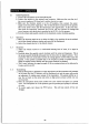
X VALUES MARKED IN SUCH MANNER ARE VALID DURING TRANSMIT ONLY, DEVICE | NUMBER | BASE | EMITTER | COLLECTOR REMARKS HEP a scars Lean a5 55 65 RIPPLE 5t Q3 25C784 0.7 0.7 5.9 TRIPLET 58 Ga 36D Bic sleaze | 0288 AE AMP X008 8100} | 1ST MIXER Fo031 25637 Ta 3 73 IND LO.