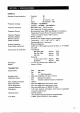
SECTION 1t DESCRIPTION 144MHz ALL-MODE TRANSCEIVER INCORPORATING A MICROCOMPUTER CPU: control with sitcom's original programs provides various operating capabilities. No-backlash dial controlled by sitcom's unique photo-chopper circuit. : Band-edge detector and Endless System provides out-AF-band protection: No variable: capacitors of dial gear; giving problems free use. The 1C-25TA/E provides EM, USB, LSB. CW coverage in the 144 ~146MHz (IC:25TA: 1438~ 148.
SECTION HI INSTALLATION : UNPACKING Cara fully remove our transceiver from: the packing carton and examine it for signs of shipping damage. Should any be apparent, notify the delivering carrier or dealer immediately, stating the full extent.of the damage. It is recommended you keep the shipping cartons. In the event storage, moving, or reshipment becomes necessary, they come in handy. Accessory hardware, cables, etc., are packed with the transceiver. Make sure you have not overlooked anything. 1.
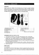
For DC operation: 1 you would like 1o use your car battery or any other DC power supply, be sure that its output voltage is 12215 Volts and the current capacity Is at least 3 Amps. The maximum power con: gumption of the set during transmission runs from 2,63 Amps; so Keep that in mind if the units installed:in your automobile.
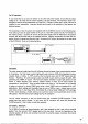
B HEADPHONES ‘Any good headphone set, melding stereo type, that has 416 ohms impedance can be used. With the plug: inserted Halfway into! the PHONES jack, ‘both the headphones and speaker will operate. : This is: convenient when others wish 1o listen in on the station; or vou wish to record contacts ‘using a tape recorder connected 1o the headphones jack. With a stereo headphone set inserted this way, however, the headphones will lose the sound on one side.
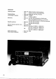
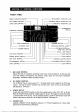
SECTION 1V CO FRONT PANEL EMULSIFICATION METER {ZRE POWER CONTROL (MIC GAIN contractual EH TRANSMIT (INDICATOR LED TUNING SPEED [ INDICATOR LED RECEIVER INDICATOR LED @SQUELCH CONTROL 2 (MIMIC CONNECTOR & PHONES JACK (BOWER SWITCH FIEF GAIN CONTROL MODE SELECT SWITCH (®RE GAIN CONTROL BV MEMORY SWITCH A FREQUENCY.
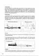
g 5. MIC CONNECTOR Connect the supplied microphone or optional microphone to this jack. The IX-SMBstand-type Electric microphone can also be used. If you wish to use a microphone other than one of these, ‘refer 10 the drawing on page 6. 6. SQUELCH CONTROL Sets ‘the: squelch threshold level.’: To: turn OFF the squelch function, rotate this control completely counterclockwise. To set the threshold level higher, rotate the control clockwise. The squelch function:operates in all-modes: 7.
addition, when the VFO is switched farm A" VFQ 1o "B” VFO, the frequency indicated oh the frequency display just prior fo switching goes into a memory: inside the CPU chip. Thus, even it "B” VFO is being used, switching to A" again will enable you 1o operate at the initial frequency. Switching Tom A to “B” results in the seem operation. RIT CONTROL Shifts the receiver frequency 3800Hz either side of the transmit frequency. When the RIT is ON, the RIT LED is illuminated.
w10 TUNING SPEED (TS) snd TONE CALL BUTTON Pushing the TUNING SPEED Button will illuminate the TS indicator LED; and the small vernier marks on the Tuning Knob are ‘changed ‘1o correspond ‘to kHz increments in any mode. At the same time, the 100Hz digits are cleared on the display to show 0" in the last digit.: When the Tuning Speed Button is depressed again; the IS indicator LED goes OFF and the small vernier marks will again correspond to SK Hz steps in the FM mode and 100Hz steps in all other modes.
23. TUNING SPEED (T5) INDICATOR LED ruminates when the TUNING SPEED Button is pressed to set the dial to kHz-step tuning. 24. RECEIVE INDICATOR LED Illuminates when the squelch is opened in the receive mode. FREQUENCY: DISPLAY The frequency: of the 1C-251A/E i displayed on'a luminescent display tube. Since the MHz and TKO decimal points are displayed, the frequency can be easily read. The frequency indicated is the carrier frequency of each mode.
Pin No. FUNCTION: 1 Output from squelch control stage. {+7V when squelch is:ON) 2. 138 Volts DC in‘conjunction with the power switch operation; {0.3A Max:} 3. Connected to Push-to-talk, T/R change-over switch. When grounded, the set operates in the transmit mode. 4; Output from the receiver detector stage. © Fixed output regardless of AF output.of Al GAIN Control: 5 Output from Transmitter MIC amplifier stage. 6. 8 :Viols DC available when transmitting.: {Relay can not be: directly actuated. SmA Max.
the twin CEO's, etc. When whitefish is set at the OFF {down) position; all the power, including that to the CPU, is turned: OFF by turning OFF the POWER Switch, so that'll the programmed frequencies in the Memory Channels, the operating frequencies of the two CEO's, sic, are erased. FUSE HOLDER This holds the fuse for the: AC power circuit. it the fuse is:blown, replace it:with a new fuse {2 Amp for 117V/1 Amp tor 240V) after cheeking the cause. Open the fuse holder with 2 Phillips head driver.
SWR s Witch When meas tiring SWR, calibration SET and SWR reading functions are selected with this switch. ‘Remember, at the factory, the switch is in the SET position and fixed in place with s plastic screw to prevent it from switching 1o SWR. Remove the screw before attempting o read SWR} SWR SET CONTROL This control calibrates the meter needle to the SET position when you want to determine the value of SWR.
SECTION. V OPERATION HOW TO TUNE The following instructions are for tuning in any mode. Please read carefully and understand fully before turning ON your unit. Proper tuning s necessary for optimum operation, PRESET FREQUENCIES When the POWER switch is turned ON, ‘the frequency display will be 145.000.0 representing 145.000.0MHz; when the VFO/Memoary Switch is in the A", “RA-RAY, "MS”, 1" 10" and #131” positions, and the display will show 145.600.0 representing 145.600.
TUNING: CONTROL Rotating the Tuning Knob: clockwise ‘increases the frequency: turning it counterclockwise decreases the frequency in 100H2 steps in the SURE, LSB and OW modes and in §KHz steps in the FM mode.: The smaller vernier marks:on the knob represent 100Hz (kHz in the FM mode): When vou reach 145.899.9 in the SSB or CW modes, or 1458950 in the EM made, timing the Tuning Control: Knob clockwise will bring the operating frequency 10 144.000.
1. The Tuning knob tension will become tighter by turning the brake adjustment screw Clockwise, and will become footer by turning the screw counterclockwise, 2. While: performing this adjustment, the Tuning knob must be turned continuously as the screw i adjusted in order 16 set the tension for a comfortable touch: DIAL LOCK SWITCH After the IC-281AJE is set at a certain frequency for rag chewing, mobile operation, stc.
A8 NOTE: The MS, ‘and: 3] positions are described in the "MEMORY CHANNEL OPERATION on page 20: M When the ICZ51AJE 35 first turned ON. 145.000.0MHz s preset into the VAT VEQ: and 145.600. MHz is preset into "B VFO. FOR EXAMPLE: When the MEMORY Switch is set in the “A” position and the set is turned ON, 145.000,0 will be displayed on the readout. This will occur whether the MEMORABLY Switch iz in either the A" or “RAT or Memory Channels positions.
FOR EXAMPLE: 11 you change the receiving frequency from 145.726MH> to 145.676MHz, the transmitting frequency will change from: 145.126MHz ‘to 145.075MHz, 5o now vou can access an 145.075/ 145.675 repeater. Setting the MEMORY Switch to RA-TS reverses the above. B When vou want to change to DUPLEX ‘operation; after using "A” VFO and B VFQ independently, and "A™ VEO and "B VFO do not have a 800K Hz frequency difference.
A When you want to change to the SIMPLEX mode ‘from DUPLEX operation, set the VFO/ MEMORY: Switch 1o the A or B position:: The transmit and receive frequency will now be controlled by “A” VEO or /B" VFO, but the other VEO will not follow this selected VFO, RIT (RECEIVE INCREMENTAL TUNING) By using the RIT circuit, you can shift the receive frequency +800HzZ either side of the transmit frequency without moving the transmit frequency itself. Therefore, when vou get a call slightly.
The programmed frequencies in the three Memory Channels are maintained as Jon as the power, including MEMORY power, of the 1C-261A/E is not turned OF F or new Frequencies reprogrammed. When the MEMORY. Switch on:the: rear panel s set 1o ON {up); all ‘the programmed frequencies on the Memory Channels and the operating frequencies of both A" and “B7 UFO's are retained even when the POWER Switch is turned OFF. SCANNING OPERATION The |C-251A/E provides various scanning operations.
Son PROGRAMMED SCAN B” As with PROGRAMMED Scan A", this Is a scanning operation between two programmed. frequencies in:Memory Channels 12 and [31; the basic difference being shown in 3 below. 1. Program the frequencies of the high and low edge of the desired scanning range in Memory Channels 2] and (31 It does not ratter in which Memory Saccharine the higher frequency is programmed, For instance, program 145.2MHz in Memory Channel [Z and 145.8MHz in Memory Channel 134 : 2.
SSB OPERATION 1. RECEIVING After connecting an antenna, microphone; tee, set knobs and switches as follows.
o4 For normal 538 reception, set the AGC switch in the AGC (up) position: Set the AGC switch in: the FAST (down) position, when tuning of receiving signals with short interval fad mg When in the FAST position, tha time constant is shortened. TRANSMITTING Before transmitting, listen in the receive mode to make sure your transmission will not interfere with other communications. | If ‘possible, Use a: dummy goad for adjustment instead 'of an antenna.
2. TRANSMITTING Insert the lever plug into the: KEY Jack on the rear panel of the unit, and set knobs and switches the same as for CW reception. By setting the T/R switch to Transmit, the transmit: LED s {it and shows that you are ready for CW transmission. . When you key the lever, the meter needle moves and our CW signal s transmitted.
6. 2. TRANSMITTING Bet knobs and switches a5 follows. MIC GAIN. CONTROL Enter (12 o’clock]) position FIREPOWER CONTROL: Completely Counterclockwise Other knobs and switches are left in the same positions as for receiving. Turn the T/R switch to TRANSMIT or push the PTT (push to talk) button on the microphone and ‘the transceiver will transmit.
Adjust the SWR SET control so that the meter needs points to "SET'! writhe meter scale. Set the SWR switch, located under the access cover, o the SWR position {Before your unit is shipped, the SWR switch is fixed in place In the SET position with:a plastic screw. : Remove this screw before trying to make SWERVE readings). With the switch in the SWR position, SWR reading con be seen on:the meter.
30 SECTION VH TROUBLE SHOOTING Your 1C:26TA/E has been tested very carefully: at the Factory before shipping. The chart below has been designed 1o help you' correct any problems which ‘are not ‘equipment malfunctions. if vou are not able o locate the problem and/or solve it through use of this chart, please contact your dealer or: [COM distributor for assistance. Problem Possible Cause Solution 1. Power doss not come ON: | Power cable: is improperly: ons: | Carefully reconnect power cabin.
Problem Possible Cause Solution 8 Mo bit put power or fow ol power RE POWER setting 18 tarried tog far counterclockwise. = lin FNM made) MIC GAIN resting is :{on low; 1in:SSB modal) When: S8B ‘o EM: is ‘desired; but the MODE switch 'is lin the CW position. PTT switch is' not functioning due:: 10 improper connection of the mic connector: The antenna: feed June s cut or shorted. Turin the:RE POWER control clocks wise | vile thatching e i function meter.
a2 Problem: Possible Cause Solution 120 The frequency: does: not ‘change by rotating the Tuning knob; DIAL LOCK is engaged. Disengage the DIAL LOCK by moving the DIAL LOG switch, 13 The science on the Tuning: knob is ot in calibration with the | displayed: fre: Frequency. The TUNING PEED button was depraved: when: the Tuning knob. s sat with: onetime the! small increments: at: the: center: point, the: Tuning: book : was rotated when: the . DIAL LOCK: was engaged.
SECTION h4 1 MAIN UNIT TRANSISTORS AGE CHARTS NOTE: Measuring instrument is a S0KS)/V multi meter. TRANSMIT RECEIVE h o, | BASE COLLECTOR| EMITTER | BASE COLLECTOR EMITTER | annoyances WATERGATE] DRAIN | | SOURCE [GATEKEEPER DRAIN | | SOURCE NEON NEON NON NEON NON aa o 17 GND | NON n Eon o1l 18 36 10 Qa2 mode o1z GND GND aND 018 a2t =78 32 10 022 024 a2 a8 88 Q28 82 3.4 —E8 az6 84 89 78 az7 135 GND 032 04 135 GND: Q34 10.0 135 8.
MAIN UNIT TRANSISTORS (Continued} TRANSMIT RECEIVE NG 3335 Emerge Bégz Liberator smoggy REMARKS Litigate DRAIN | SOURCE INVESTIGATED DRAIN | source adz 20 50 14 643 o 70 08 044 25 15 23 Q45 o 9.0 .3 Q46 0 o 88 GND 047 048 050 50 92 46 as2 02 748 GND o83 ass 06 o GNB 9 92 GND | OXONIAN 086 OXONIAN as7 VOX ON Q88 GND 0 64 GND asd 06 0 GND a8 8 GND a8l GND 67 9 GND g3 107 74 GND o 9 GND gss roan 84 50 ass 84 90 91 Q86 ash 832 0 072 82 Q 8.6 073 arn 19 ™ 13 MAIN UNIT IC IN.
MAIN UNIT IC IN RECEIVE MODE PIN annulled e et 26|20 ;0101261363238 163 50|16 Tonne 69 28 638 1G5 19]o biases) 78135135 18 107 5.0 loin] a7 168 ag|solsoleaizsl 18 1ol 1816 60 PLL UNIT TRANSISTORS TRANSMIT RECEIVE TR NG COLLECTOR REMARKS (TAILGATE | DRAIN SOURCE PROFLIGATE! DRAIN SOURCE ai i 5 GND i 3 GND 02 x: * GND » GND. 03 17 685 GND 85 20 | GND 6.5 20 [VCO Unit VoD Unit Q10 732 atl 0 9.8 GND 0 08 GND Q12 100 013 | 6ND 06 0.
36 DRIVER UNIT TRANSISTORS TRANSMIT. RECEIVE TR NG, nge COL EM!O SEES oL Locator REMARKS CASTIGATE DRAIN SOURCE INVESTIGATE . DRAIN SOURCE 0.65 0.85 g 065 085 0 Qi l38 8.6 138 13.8 88 138 a8 065 138 0 .85 138 o a9 Q 13.8 g G 138 o Qio Q.75 o 0 Q12 TRITON RIPOFF NOTE: Ether devices work in C-MOS level and with pulse signals; so the voltages can not be measured with a 50KV multi meter. The function: of the CPU is identified with reading the relationship between the B output and the: Putin signals.
AC POWER: SUPPLY UNIT The AC power supply built in the unit is a newly developed switching regulator system, providing light weight and a high level of efficiency. PIL UNIT The AC power supplied from Pins 2 and fed 1o the memory power transformer L2, The 'output voltage from ‘the secondary of L2 is rectified and filtered by D2 and C7, and switched by Q1 before being fed to the SW. REG Unit. The rectified and filtered power is put out also to the fourth Pin.of Pl as the 10 = 14V memory: power source..