Use of Microcomputer This (G280 s ahe world's first amateur transceiver with s Pi channel MOS 4:bit microcomputer. Frequency control] band-edge detection, and the display are accomplished by the microcomputer. The 3-channel memory Is controlled electrically by the use of & 256-bit RAM area.. The circuits for these 1-280 functions are equivalent-in capability to conventional circuits having a large number 0 C-MOS MS's.
SECTION 11 INSTALLATION Unpacking: Carefully remove your transceiver from the packing carton and examine it for sign of shipping damage. Should any be apparent. notify the delivering carrier or dealer immediately; stating:the full extent of the damage. 1t is recommended you keep the shipping cartons. ' in the event storage, moving, or reshipment becomes necessary, they come in handy. Accessory hardware, cables, sic., are packed with the transceiver. Make sure you have not overlooked anything. 1.
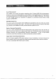
Angles adjustment D Optional installation Power Requirements: The ‘transceiver is supplied ready to operate from eny regulated 13.8V DG, 3 ampere negative ground source. An automobile 12 volt, negative ground, system s usually more than adequate, Some note must be taken, however, of the condition of the vehicle’s electrical system,. rems such as low battery, womb generator/alternator, poor voltage regulator; etc., will impair operation of your transceiver as wells the vehicle.
Antenna: The most important single item that will influence the performance of any communication system isithe:antenna: : For that reason; g good; high-quality; gain: antenna of 50: ohms impedance & recommended, fixed or mobile. In: VHF a5 well s the law bands, Avery watt of ERP makes some difference; Therefore, 10 wails average output plus 3dB of gain antenna equals 20 watts ERF, presuming low: SWERVE of course.
SECTION. 1V, CONTROL FUNCTIONS : FRONT: VIEW Quantifier Display-— it et Dupkex/Simiplax Swish Receptive Indicator s Duplex Mode Select Switch (E Transmit indicator <5 Marguerite Switch & Memory Chan net Switch B High/Low Power Switch MIC Connector HI VOL Controlling Ewer. . ONION Swish e SOL Control H)Tuning Contralto i Transmit Indicator: Illuminates in the transmit mode. . Receive Indicator:: Ruminates in the receive made, : (When squelch opened ). .
CONTROL INSTRUCTIONS Duplex/Simplex Select Switch For repeater use, set this switch to the Duplex position by depressing to the locked in position.
flora Toed (o f ‘ Initial Preparations: Marie sire the MOL Control and Power OFFENSE Switch i the QFF position, then consist the power supply ford to the power connector. The'red lead should be connected to the positive side ‘of the power source and the black lead to the negative side. Iri the event that these leads are improperly connected; the transceiver will not function: Reversing polarity will blow out the fuse in the power supply cord due to actuation of the protective circuit.
If the Tower output power is sufficient, set High/Low Power Switch to the LOW position, Depress the PTT switch on the microphone for transmitting and release for receiving.
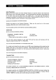
ARV General The 1-280 has a digital Phase Locked Loop circuit for its local oscillate. The PLL circuit is controlled with a programmed microcomputer developed by ICON. The band edges, memory channels and duplex setting are programmed in the computer. The received signal s mixed with the output signal of the PLL circuit and converted into the 10.695MHz [F signal.
13 AE Circuit The demodulated signals are fed to the DE-emphasis circuit to equalize the high pitch tone which is per-smphasized at transmit. | Then the signals are fed to the 1C4-1 attenuation element which turns ONESELF the audio signals by the signals from the SOL circuit. The output signal from 1C4:1is fed to the control unit through J1.
Power Circuit The train unit has a continuous 9V regulator, Q7 and & receive mode 9V regulator, OB, By supply: ing the voltages to D15 Zenger diode through REB, the base voltage of Q7 asset af 9.6V, The collector of 07 is connected to the power supply through R85 and regulated voltage is put out at the emitter for the PLL unit.
5 VCO circuit Q8s an oscillator and (9 is 4 buffer. In the transmitting mode, the VCO signal is frequency modulated by the audio signals: from the ‘microphone through: the varicose: D8, and the output frequency:isithe transmitting frequency.
‘The pulse signals are put out at RO-R2Z of the CPU in order, synchronizing with the segment display: data outputs 01-07 and 01-03 are turned: ON:by these pulse signals: Q1 is:for the MHz LED, Q2 s for the 100KHz LED and Q3 js for the kHz LED. When the power is turned is turned ‘ON:and the display ‘operation became possible Q1 s turned ON by the RO 7-segment signals {01:07) are fed to 1C12 for the MHz display. The same data is converted ‘to BCD, 2 is subtracted and: put out at R7-R9 of the CPU.
IO Fell Your 1-280 has been tested very carefully at the factory before shipping.. The chart below has been designed to help you correct any problems which are not equipment malfunctions. If you are not able to locate the problem and/or solve it through Use of this chart, please contact your 17 dealer or |COM distributor for assistance. Problem Possible Cause Solution 1. Power cannot be turned ON. {proper: ‘connection i of the power cord Male-contacts: iof the © power connector.
1@ PLL U NIT TRANSISTORS TRANSMIT: RECEIVE TR No. Beige EMg’gSR Beige CO&IbEgTDH BASEMAN GATE 1 GATE 2 DRAIN SOURCE |GATE LIGATE 2 DRAIN SOURCE Qi 0.05 32 OND: 068 0 GND Q2 Q.87 0:0% GND 068 0 GND: 248 GND 0.7 4.9 GND: 08 1.2 78 085 12 7.8 055 Q7 18 e84 85 94 BUE 8.8 a8 Defeated a9 Mediated Q10 012 g0 11 10 0:22. 025 Q1Y 075 o8.2 08 0.9 013 011 012 * w* GND: * * GND a1y 45 7.3 40 0.02 013 003 018 Q15 065 001 GND 0.65 8.01 GND. i & Wuhan the Sock is released, goes to 8.
We have prepared a variety of options for the mobile transceiver 1-280 in order t0 enlarge its use REMOTE: CABLE KIE: DG POWER CORD WITH MEMORY. BACKUP: POWER:PLUG PECTIC 1C:5M2 POWER: SUPPLY. DESK: MICROPHONE 138V 3A ELECTRIC CONDENSER.