FIRST APPLYING POWER The 1C-3SAT includes Nitric batteries and a rechargeable backup battery. H:the batteries are low ‘at the time you purchase the [G-35AT, the transceiver may not operate properly. : 1f the transceiver malfunctions, reset it as follows: 1} Connect the supplied wall charger to the [DC 13.8 V] jack on the top panel 91 While pushing [E] and [AL(CLR), rote [PROVOLONE] 1o turn ON power. 3) Release the switches. » The function display shows 220.00 MHz.
CAUTIONS IMPORTANT READ ALL INSTRUCTIONS carefully and completely before using the transceiver; SAVE THIS INSTRUCTION MANUAL This instruction manual contains important safety and operating instructions for the SATANIC. OPERATING NOTES BE CAREFUL! When transmitting for a long time with high output power, the rear. panel may become hot. ‘ When using the transceiver with the internal battery, we recommend operating with low output power.
i FOREWORD UNPACKING Thank you for purchasing the 1C-38AT 220 MHz EM TRANSCEIVER, The SATANIC s 3 state of the-art hand: held. that fits. comfortably in the palm of your hand and combines ease of use with multi-operational capability. Features include keyboard selection. 5 W output power. a power saver function, auto power off. power on timer, bully-in clock, 48 memory channels, 10 MDT memory channels, priority watch, convenient scan functions, eic.
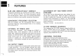
1 FEATURES SLIM AND UNBELIEVABLY COMPACT Transceiver dimensions are just 49 mm {1 99W % 103 mim (147D And these dimensions include the internal battery! What's more, the rounded body design gives you a feeling of even smaller transceiver dimensions.
2-1 Attaching accessories PER-OPERATION { ANTENNA AND RAINPROOF CAP connecting the ‘antenna when desired. insert the supplied antenna onto the antenna connector and twist the connector on the antenna as shown in the diagram at left. Attach the rainproof cap before o HAND STRAP ATTACHMENT The hand strap allows you 1o easily carry the transceiver. Attach | the handstand ' 83 shown in the diagram at left. The belt clip allows you 10 attach the transceiver 10 your belt: Remove the . plastic screws.
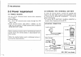
wl 2 NONCOOPERATION 2-2 Power requirement {1) POWER SOURCE ‘ Use any of the following power sources when operating your 1C-35AT; » Internal battery: external power source through the [DC 13.8 V] jack. e Either optional battery packs BP-81 ~ BP-85 or six AA {R6) size dry batteries or Ni Cd batteries with an optional BP:90 BATTERY CAVE. When attaching a battery pack or ¢connecting an external power source, the internal battery is disconnected from the circuitry.
{3) CHARGING AN OPTIONAL BATTERY PACK An optional battery pack car be charged in a similar way as the internal battery. The internal battery will not be charged when an external battery pack is constricted. CHARGING CONNECTION {DC 138 V] (BP-81 Supplied wall charger U 9 B CO-12 {optional) Cigarette fighter: socket I GPC«ZSA {optional) (BPOE cantor e charged with BC-720) To external power supply USE ONLY one charger.
MODE CONSTRUCTION 3.1 Mode types The transceiver has b different modes and 1 call channel for versatile, multi-function operations. «VEO MODE Used: for normal operations over «CLOCK MODE Used for setting the clock time, the entice band. power on timer and auto power off time: E St Used for operating the transceiver e DEFEAT MEMORY Used for programming MDT codes. using memory channel contents. 48 MODE 10 DEFEAT memory channels are memory channels are available for available and each channel hasp programming.
3-2 Mode construction chart MEMORY MODE (p. 19) VFO MODE (p.14) R MODE CONSTRUCTION dice Al ol Scummed CASTLEREAGH CALLAGHAN 2uh LACE CHANNEL {p.22) @ +azéumr DIME MEMORY MODE {n.29) CLOCK MODE (p. 30} Elma Y @ SET MODE Offset frequency [p. 18] Subdivide tone frequency. p.41) {optional) Akt Tuning step p.
N 4 PANEL DESCRIPTION 4.1 Switches and controls MICROPHONE SPEAKER KEYBOARD BOTTOM CAP ® o ANTENNA CONNECTOR Connects the supplied flexible antenna. {p. 4} EXTERNAL DC POWER JACK [DC 138 V] Connects: the supplied wall charger for charging the internal or attached battery pack: Allows operation: with a 13.8 V. DC power source using optional cables CO-12 or OP-254 [see ached “List of options’ for details} The wall charger cannot be used to Operate the trans: caver.
& TRANSMIT POWER SWITCH [H/L/DTMF] Selects high or low transmit output power. (p. 16} While pushing this switch and rotating the tuning control, the low output power level changes, {p. 17} While pushing [E]. push this switch to enter DIME MEMORY made. (p.29) @ MONITOR SWITCH [MON II Opens the squelch and optional tone squelch. (p. 16) Checks the transmit frequency when duplex is selected. p.12) While pushing [F], push this switch to turn OFF the green receive indicator.
4. p Panel DESCRIPTION 4-2 Keyboard 171 801 Turns ON and OFF an optional sub audible tons encoder or l@m) m@sou SOPORIFIC L Ski R CE%V tone squelch function: {p. 41) PGR/CS0L e Turns ON and OFF an optional pager or code squelch function. (pgs. 38 ~ 40) ski THO ot S When selecting MEMORY mode: Programs the memory channel as the skip channel. Selects in sequence; —-duplex = +duplex simplex. (p.
a When selecting VEO of MEMORY mode: Change the operating frequency of memory channel . (pus. 14,20) PANEL DESCRIPTION 4 V/SCAN To Starr full scan or memory scan, push and hold dither key. (p. 24) When selecting VEQ mode: Start programmed scan. s s When selecting SET br CLOCK made: | (28] Change the display contents. (pgs. 8, 30) s When selecting DEEM MEMORY mode: ‘No function. s When selecting VEO mode: Clears input digit before entry. When selecting MEMORY mode or call channel: Transfers Clime (p.
4 PANEL DESCRIPTION 4-3 Function display gingersnap@ o @—{3 LR!O LOW -IEB!BIII55 9 @ FUNCTION INDICATOR Appears while pushing [F1. @ LOCK INDICATOR Appears when the lock function is activated. {p. 15} © DUPLEX INDICATOR DUMPY or "-DU PRY appears when dug!ex is: selected. . 171 @ TONE INDICATOR Appears when aerating the sub audible tone encoder or tone squelch function: {an optional UT-50 or UT-51, see ““List of options,” is necessary ) (pgs.
5.1 Setting a frequency Before applying power, see the inside front cover to reset the transceiver. {1) USING THE TUNING CONTROL 1) Rotate [PROVOLONE] to turn power ON. 2) Push [A] {CLR) to select VFO mode. 3) Rotate the tuning control to set an operating frequency. BASIC OPERATION D il (2) USING THE KEYBOARD 1) Turn power ON. See steps 1 and 2 at left. 2} Push the appropriate digit key to input the frequency. » When the wrong digit is input, push [A] (CLR} 1o clear the input.
B 5 BASIC OPERATION (3) SETTING A TUNING OR DIAL SELECT STEP — use SET MODE B SETTING A TUNING STEP The display shows the Twining step for 20 kHz. 1) Push [AL {CLR} to select VFO mode. 21 While pushing [E], push [81{SET) to enter SET made! s Refer to p. 8 for SET mode details. 3) Push or [Hail) nth “7S7 appears as Shawn above. 4) Rotate the tuning control to select the desired tuning step, 5} Push [ALICIA) 1o exit SET mode. B SETTING A DIAL SELECT STEP While pushing [F].
5-2 Receiving 1) Set [SQUELCH] to maximum counterclockwise. 2) Rotate [FRIVOLITY 1o turn ON power and adjust the audiophile 3} Rotate [Sought} clockwise until the noise disappears. 4) Set the operating frequency using the tuning control ar keyboard. » Refer to p. 14 for details. | 5} When receiving a signal 0n the set frequency: = Squelch opens and the transceiver emits audio. i The SURFER indicator shows relative signal strength. 6) Use MONORAIL when a weak signal cannot open the satiric completely.
17 5 BASIC OPERATION B SELECTING LOW OUTPUT POWER Low output power can be selected in 3 levels to suit operating requirements such as communication distance, battery conservation, etc. LOW 1 LoW e oEW 05W Low 2 LOW Eminence 15W 1.8W LOW 3 LOW Semibreve 35w 15W HIGH Sereneness 5.0W 15w Above values are cervical: While pushing rotate the tuning control. a The S/RE indicator shows output power selection as described abase.
BASIC OPERATION 5 i INAUDIBLE TONE ENCODER (An optional UT-50 or UT-51 is necessary} T appears While pushing [F], push [11{T/T ~nw% SOL) until T appears. 22385 o To set a2 sub audible tons frequency, see p. 41 s DIME TONES W@ While pushing [PT, push the o8 desired digit key to. transmit &5 5 Tombstones S e o0 The transceiver has 10 DIME memory channels. | Each memory has the capability to memorize up 10 18 DIME digits. See p. 29 for details.
Bl O MEMORY OPERATION 6-1 Selecting a memory channel (1) USING THE TUNING CONTROL 1) Push [B] IMR] to select MEMORY mode. The transceiver has 48 memory channels for stoning your * MR’ appears mast-often-used frequencies such as for use with repeaters, group calls, gtc.
MEMORY OPERATION B i {2) USING THE KEYBOARD 6-2 Writing a memory 1) Push (Bl (MR several times to select the desired 10-digit memory channels 1) Select the memory channel to be programmed. # See Section 6-1 for details. 2) Push ‘the appropriate digit key to select the memory channel; e Pushing and also allows you to select memory channels. 2) Push [A] (CLR] to select VEO mode. 3} Seethe frequency (and duplex when réduired): 3} Push [A§ {CLB) to return to VEO mode. 4} While pushing [E].
6 MEMORY OPERATION 6-3 Transferring a memory Copy and transfer the displayed memory contents into the VEO. . This function is useful for searching for signals around the memory frequency. and for recalling the offset frequency which is independently programmed in memory channels 0 ~ 9, Push and hold ®+ MEMORY MODE COMMODE 1) Push [B] (MR} to select MEMORY mode, 2} Select the memory channel:to be transferred: : Rotate the tuning control or push [B] several times then push a digit Key.
CALL CHANNEL OPERATION 7-1 Calling up the call channel A one touch access call channel is provided for operation on: your most-often-used frequency. The call channel is separate from the memory channels. illiberal CALL CHANNEL COMMODE 1)} Push IDYLLICALLY} to wall up the call channel. 2) Push [DI{CALL) again to return to the previous made.
I 8 o SCAN OPERATION 8-1 Scan types The I1C-3SAT has 3 scan types and 2 skip functions as described below. Perfect for hands-free operation. = FULL SCAN Repeatedly scans all frequent PROGRAMMED SCAN Repeatedly scans between two ices in. the entire 220 MHz Span edges user-programmed . frequencies. 220 Wiz oM band. . The frequency skip / N Ses p. 24 for scan edge pro Scan function can be used, et b ramming. The frequency skip function can be used.
8-2 Scan operation FULL SCAN Push [A] 1o select VEO mode, Push: ‘and’ “hied {2l or fart sec. PROGRAM: MED SCAN Push [A] 1o select VEO mode: While pushing (k] push tx] or 3. MEMORY SCAN Push [B] to select MEMORY made: Push: gnd hold or izl ford fee. £ SCAN OPERATION 8 Refer 1o the following table for any scan operation: However, before operating a scan, rotate the [SQUELCH] control clockwise until audio is muted. #Scan resumes 10 sec. afresh ‘aisignaliisireceived or 2 sec after a'signal resumes.
8 SCAN OPERATION 8-3 Setting scan conditions (1) SETTING THE sie SET MODE PROGRAMMED SCAN EDGES il e Scan edge frequency A Scan edge pregnancy B 1) Push [ALICIA) to select VFO mode, 2} While pushing {F] . push I81{SET) to enter SET mode, s Refer to p. Biro SET mode details. 3) Push [+ () ar [#104) until “PAY appears as shown above, 4} Set g scan edge frequency using the keyboard or tuning control. 5) Push [4 (A} ("PB" appears), ‘then set the other Sean edge frequency. 6} Push [A] (CLR) to'exit SET mode.
use SET MODE B FREQUENCY SKIP FUNCTION ON/OFF an T 1) Push [A] (CLR) to select VEO mode. 2} While pushing [F1, push [81(SET) to enter SET mode, s Refer to p. B for SET mode details. shown above. 4} Rotate the tuning control to tern ON or OFF the frequency skip function. 5} Push [A] (CLR) to exit SET mode. Skippy function is ONL Skip function s OFF. 3 Push or until "PS" appears a5 SCAN OPERATION 8 f (4) PROGRAMMING A MEMORY SKIP CHANNEL Memory channels not desired can be skipped: during memory scan.
. O 9-1 Priority watch types 27 PRIORITY WATCH o VED MEMORY CHANNEL While using a VFO frequency, priority watch checks the *VFO <= CALL CHAIN EL While using a VEO frequency, priority watch checks the call VEO secrecy priority © watch checks each memory: camel. . You can also ‘program skip channels which willing “be watched, miking shorter swanning revivals; Start the watch during memory. Sean. Sec. semipro selected memory channel channel in B sec. intervals, sec; intervals.
9-2 Priority watch operation VEO <> MEMORY CHANNEL 1) Set the memory channel to be watched. 2) Push [A] to select VEQ mode. VFO <> CALL CHANNEL Push [D] to call up call channel, VFO ¢ MEMORY SCAN 1) Push [B] 1o select MEMORY mode. 2) Push ind doth start memory scan. White pushing [F1. push 7l 1 Refer to ‘the following table for any priority watch operation: However, before operating the watch Unction, rotate [SQUELCH] clockwise until audio is muted, e Priority watch pauses. for 15 sec.
29 10 MDT MEMORY OPERATION 10-1 Programming a MDT code 5) Push [H/L/DTME] to store the input digits. The transceiver has 10 MDT memory channels for storing your most-often-used DIME codes digits. 1} While pushing [F1, push [H/L/DTME] to enter DIME MEMORY mode. 2) Push a digit key to select the desired channel. 3} While pushing [F], push [81(SET) to program the DIME memory. : & Previous programmed digits are erased. A} Push the appropriate digit keys to input the DEFEAT code.
CLOCK AND TIMER OPERATION 11 ISR 11-1 Clock mode 11-2 Setting time The :transceiver is equipped: with: 2 clock function for operating the power on timer and auto power off timer. +&H 1} While pushing [F]. push {91 [CLOCK] to enter CLOCK mode: Uiy 1 @ 2} Push [PTT] to return to the previous mode. 1) While pushing [£ 1, push [9] {CLOCK) 1o enter CLOCK mode: 2) Push () or to select the clock time display as shown above; 3) While pushing [F], push [BI(SET).
11 c Lock AND TIMER OPERATION 11-3 Power on timer The transceiver has a power on timer to fit your schedule and to save battery power. While the timer is activated, the transceiver is in the off condition, the function display shows the clock: time and the transmitter and receiver circuits do ot operate. : e SRR o 8Y Push: or [#1 LAY, then rotate the tuning control to set the minutes. 73 Push RETALIATORY 1o set the time.
Betting time at 9:30 and the power on'time ‘at 15:00. [EXAMPLE] 22350 CLUE el T Sean o & e ,,wurst it and BOATMAN WELLS et 3 b contrary ser q-j x4 Dot appears wherewith power on timer i ON: | CLOCK AND TIMER OPERATION 11 114 Auto power off The transceiver automatically turns OFF after the selected time ‘when ‘ro switch is pushed or no signal i3 received. Time can ‘be set in 20,40 ‘and B0 min. intervals. The function can also be deactivated urging the "oFF ' setting.
BB 12 BEEP AND POWER SAVER 12-1 Beep tone ON/OFF elusive SET MODE. The ‘transceiver emits a beep dong each time a switch is pushed. To turn OFF the beep tone, use SET mode. e ) Beep iz emitted. Beep isn't emitted. 1) Push [AJ{CLR) 1o set VEO mode. 2) While pushing [F] push [81(SET) to enter SET mode. o Refer to p. 8 for SET mode details: 3 Push [=100) or [#110) until "BE" appears as shown above. 4} Rotate the tuning tricolor to select beep "on” or 51 Push [A CLERIC) 1o exit SET mode.
13-1 Unit installations (1) DISASSEMBLING THE TRANSCEIVER 11 Turn power OFF then remove the bottom cap. 2} Unscrew the 5 resews.
13 OPTIONAL UNIT OPERATION 13-2 Pager function The pager function transmits a code with 7 MDT digits: Transmit code * "= + your 1D dose. The pager function accesses other stations and displays a code identical to: yours: using the other station’s display. An optional UT-48 DIME DECODER UNIT is necessary This function can be used for group communications. for operation. s+ PERSONAL CALL Code [ Programming ‘channel example 1D code of Station A Channel :C1 s selected: as'the transmit code.
PER-OPERATION: 1) Install optional LIT units in your group transceivers. 2} Decide the 1D code of each transceiver and the group code in your group. 3} Decide whether to return to normal operation or code squelch operation after contact: OPTIONAL UNIT OPERATION 13 1D codes as transmit codes. (p. 37) memory channel CO. 4) Program the 1D code, group aced, and the other station's e Your 1D code should be programmed into the aced » Program ‘receive inhibit” on channels programmed as transmit codes. code.
37 13 OPTIONAL UNIT OPERATION {1} CODE MEMORY CHANNEL INFORMATION GO Your 1D code Accept only €1 Weatherization's c2 1D codes | Electable Possible €3 {Transmit code) | acceptation C4 or inhibit Ch group code op Memorizing inhibit Not space” only: Applicable * Automatically memorizes the 1D code of the other station when receiving a ‘call, | This memory is Kept until the next call is received.
{3) PAGER OPERATION ‘ B PERSONAL CALL PER-PROGRAM CO: 1D code of 1117 L Gh: Ration B's 1D code of 112227 OPTIONAL UNIT OPERATION 13 P The following operation procedures should: be started after completing the steps described in PER-OPERATION on p. 36. REPROGRAM CO: {0 code of 222" 1} While pushing {F1, push (21 10 turn ON the pager function: 1) While pushing [F], push {2] (PGRIC-SQL) 1o e ON the pager function.
13-3 Code squelch The code squelch function provides you with “personalized communication using 3D TME digits. An optional UT-48 DIM DECODER UNIT is necessary for operation. *TURNING ON THE CODE SQUELCH ® & 2 times s Selecting THE MDT CODE O+ @ 22dhh rnl YT e OPTIONAL UNIT OPERATION 13 1) Decide the 1D code on gate transceiver antithetic group code in your group! 2): Program the |D code; group code, and the other station’s 1D codes as transmit codes. (p.
41 13 OPTIONAL UNIT OPERATION 13-4 Sub audible tone encoder When' a repeater requires a digestible tong, an optional UT-80 or UT-51 unit is necessary. 1) While pushing [E], push » T appears on the function display. o When the UT-50 is installed, push the switch until only T appears. 2} To set a sub audible tone frequency, see right. 3) To turn OFF 3 sub audible tone, repeat step 1 until 117 or T 501" disappears.
14-1 Troubleshooting MAINTENANCE 14 . are erased charging has been performed for a loan time. is charged simultaneous, «No power comes on. ® The internal battery requires charging. # Charge the internal battery. pib * The external battery pack requires charging | @ Charge the battery pack. When connected | p. 5 when connected. the internal battery is not used, ® Poor plug connection when using an external’ | & Check the connection or remove the cable.
14 maintenance 14-2 Backup battery 14-3 Cleaning The transceiver is equipped with a rechargeable lithium IT the transceiver becomes dusty or dirty, wipe it clean with backup battery for retaining memory information. dry, soft cloth. AVOID the use of chemical agents such as benzine or alcohol. as they can damage transceiver surfaces.
I SPECIFICATIONS GENERAL . B TRANSMITTER ® Frequency coverage 122000 225,00 MHz B Out Put Po veer Highlight More than B.OW {at:12.8 V. DC) Low: @ 35/15/05W (delectable) & Mode HUE MARS) & Modulation system 12 Variable reactance frequency ® Antenna impedance = 1560 & unbalanced. modulation » Acceptable external negative ground or frequency deviation S b kHz power solace battery packs BP-81 ~ 85, BP.