INSTRUCTION MANUAL UHF C.R.S.
IMPORTANT PRECAUTIONS READ ALL INSTRUCTIONS carefully and com- R CAUTION! NEVER hold the transceiver so that the pletely before using the transceiver. antenna is very close to, or touching exposed parts of the body, especially the face or eyes, while transmitting. The transceiver will perform best if the microphone is 5 to 10 cm away from the lips and the transceiver is vertical. SAVE THIS INSTRUCTION MANUAL — This instruction manual contains important operating instructions for the IC-41S UHF C.R.S.
DO NOT modify the transceiver for any reason. KEEP the transceiver from the heavy rain, and never immerse it in the water. The transceiver construction is water resistant, not waterproof. The use of non-Icom battery packs/chargers may impair transceiver performance and invalidate the warranty. This device complies with Standard Australia Specification No. AS/NZS 43652002 and AS/NZS 4295: 2004.
TABLE OF CONTENTS iii IMPORTANT ................................................................................ i EXPLICIT DEFINITIONS ............................................................. i PRECAUTIONS ........................................................................... i TABLE OF CONTENTS .............................................................. iii 1 ACCESSORIES ................................................................ 1–3 ■ Supplied accessories .............................
ACCESSORIES ■ Supplied accessories Flexible antenna Battery pack Battery charger ■ Accessory attachments 1 1 DFlexible antenna Connect the supplied flexible antenna to the antenna connector. CAUTION! • NEVER HOLD the antenna when carrying the transceiver. • Transmitting without an antenna may damage the transceiver.
1 ACCESSORIES ïBattery pack DBelt clip To attach the battery pack: Slide the battery pack in the direction of the arrow (q), then lock it with the battery release button. To attach the belt clip: q Release the battery pack if it is attached. w Slide the belt clip in the direction of the arrow until the belt clip is locked and makes a ‘click’ sound. • Slide the battery pack until the battery release button makes a ‘click’ sound.
ACCESSORIES 1 ïJack cover 1 Attach the jack cover when the optional speaker-microphone or headset is not used. To attach the jack cover: q Attach the jack cover to the [MIC/SP] jack. w Tighten the screws using a Phillips screwdriver. [MIC/SP] jack q To detach the jack cover: q Unscrew the screws using a Phillips screwdriver. w Detach the jack cover for the optional speaker-microphone or headset connection. q w Jack cover w q CAUTION! Use the supplied screws only.
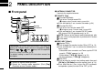
2 PANEL DESCRIPTION ■ Front panel q w q ANTENNA CONNECTOR Connects the supplied antenna. w TOP KEY* [Top] N (Function/Set Mode) ➥ Push to turn Function mode ON. y e u r Speaker Microphone t • “F” appears when Function mode is turned ON. ➥ Push and hold for 2 sec. to enter Set mode. (p. 34) F (Function/RX VFO) ➥ Push to turn the Function mode OFF. • “F” disappears when Function mode is turned OFF.
PANEL DESCRIPTION r PTT SWITCH [PTT] (p. 12) Push and hold to transmit; release to receive. t CH UP/CH DOWN KEYS [CH UP]/[CH DOWN] Push to select an operating channel, set mode setting, etc. (pgs. 11, 34) y VOLUME CONTROL [VOL] (pgs. 10, 11) Rotate to turn the power ON/OFF and adjusts the audio level. u EXTERNAL MICROPHONE/SPEAKER JACK Connect an optional speaker-microphone or headset. NOTE: Connect or disconnect the optional equipment after the transceiver is turned OFF.
2 PANEL DESCRIPTION !1 PRIO/SET•P KEY* N (PRIO/PRIO Set) ➥ Push to select the priority channel. (p. 13) ➥ Push and hold for 2 sec. to set the displayed channel as the priority channel. (p. 13) F (S-Ring/PRIO Clear) ➥ Push to transmit the Smart-Ring signal. (p. 30) ■ Function display qw e r t yu i o • When RX channel is selected, “N/A” appears. ➥ Push and hold for 2 sec. to cancel the priority channel setting. (p. 13) !2 LOW/“ ” KEY* N (RF Power/Lock) ➥ Push to toggle the transmit output power level.
PANEL DESCRIPTION t BELL INDICATOR ➥ Appears when the pocket beep function is in use. (p. 24) ➥ Blinks when the specified SelCall or Smart Ring call is received. (pgs. 28, 30) !3 OPEN SCAN INDICATOR (p. 19) Appears when the ‘Open scan’ is selected. y QUIET INDICATOR (p. 29) Appears when the Quiet function is ON (SelCall mute is activated.) !5 PRIORITY SCAN INDICATOR (p. 20) Appears when the ‘Priority scan’ is selected. u PRIORITY CHANNEL INDICATOR (p. 13) Appears when the priority channel is set.
2 PANEL DESCRIPTION ■ Programmable function keys The following functions can be assigned to [Top], [Side1], , , and programmable function keys with the optional CS-41S CLONING SOFTWARE. The key function activates after pushing [Function] when the programmable function key is assigned to the function mode operation. If the programmable function names are bracketed in the following explanations, the specific key is used to activate the function depends on the programming.
PANEL DESCRIPTION Quiet/ID-MR ➥ Push to quiet function ON or OFF (CB channel operation only). ➥ Push and hold for 2 sec. to enter the received ID code history indication mode. SQL/ATS ➥ Push to enter the squelch level setting mode, then push [CH Up] or [CH Down] to set the squelch level. ➥ Push and hold for 2 sec. to turn the ATS (Automatic Transponder System) function ON and OFF. Dup/Zone ➥ Push to set the selected channel as Duplex or Simplex operation.
3 BASIC OPERATION ■ Turning power ON Prior to using the transceiver for the first time, the battery pack must be fully charged for optimum life and operation. (p. 39) q Rotate [VOL] to turn the power ON. w If the transceiver is programmed for a start up password, input the digit codes as directed by your dealer. • The keys in the table below can be used for password input: • The transceiver detects numbers in the same block as identical. Therefore “01234” and “56789” are the same.
BASIC OPERATION ■ Channel selection ➥ Push [CH Up] or [CH Down] to select the desired channel. • While pushing and holding [CH Up] or [CH Down], the displayed channel changes continuously until channel 1 is selected. • When channel 1 is selected, beeps are emitted. • ‘CB-XX’ appears when the CB channel is selected and ‘RX-XX’ appears when the RX channel is selected. 3 ■ Receiving and transmitting NOTE: Transmitting without an antenna may damage the transceiver. See page 1 for accessory attachments.
3 BASIC OPERATION Transmitting: Wait for the channel to become clear to avoid interference. q While pushing and holding [PTT], speak into the microphone at a normal voice level. •“ ” appears. • A PTT hold function is available. See p. 33 for details. w Release [PTT] to return to receive. [PTT] IMPORTANT: To maximize the readability of your signal; 1. Pause briefly after pushing [PTT]. 2. Hold the microphone 5 to 10 cm from your lips, then speak into the microphone at a normal voice level.
BASIC OPERATION 3 ■ Priority channel setting The priority channel, simply recalled by pushing (PRIO), and also is automatically monitored during the priority scan. You can set the only one channel as the priority channel. “P” appears when the priority channel is set. DSet the priority channel q Select the desired channel. (p. 11) w Push and hold (PRIO Set) for 2 sec. to set the displayed channel as the priority channel. 3 DThe priority channel selection ➥ Push (PRIO) to select the priority channel.
3 BASIC OPERATION ■ Monitor function ■ Adjusting the squelch level This function is used to listen to weak signal or to open the tone squelch manually. In order to receive signals properly, the squelch must be adjusted to the proper level. ➥ Push [Side1] (Monitor) to toggle the monitor function ON and OFF. q Push [Top] (Function) to enter the function mode, then push [Side1] (SQL) to enter the squelch level setting mode. w Push [CH Up] or [CH Down] to adjust the squelch level within 0 to 9 ranges.
BASIC OPERATION 3 ■ Display backlighting [ ■ Set mode The transceiver has display backlight for night-time operation. Set mode is accessed at power ON and allows you to set seldom-changed settings. In this case you can “customize” the transceiver operation to suit your preferences and operating style. See p. 34 for set mode items detail. q Push and hold [Top] (Set Mode) for 2 sec. to enter set mode. w Push [Top]* several times until “LIGHT” appears.
4 REPEATER OPERATION ■ Repeater operation ■ Accessing a repeater Repeaters allow you to extend the operational range of your radio. Normally, a repeater has independent frequencies for receive and transmit. A repeater amplifies received signals and re-transmits them on a different frequency, allowing you to communicate over greater distances with improved reliability. When using a repeater, the repeater output channel (‘CB-R1’ to ‘CB-R8’) must be selected.
5 SCAN OPERATION ■ Scan types The transceiver has 4 scan types, tag function and 4 resume conditions providing scanning versatility. OPEN SCAN Tag channels are independently set for open, group and priority scans. Initially, all channels may be set as tag channels for all scans. 4 5 REPEATER SEARCH SCAN ch 1 ch 2 ch 3 CB-R1 ch 40 ch 4 ch 39 ch 6 ch 5 CB-R2 CB-R8 Scan cancel CB-R1 CB-R8 Repeatedly scans all tag channels in sequence.
5 SCAN OPERATION ■ Scanning preparation IC-41S scans all tagged channels, and can be selected so the scan resume condition is a pause or timer scan. Therefore, these items must be set before starting a scan (except the repeater search scan). These items must be set for each scan type (open, group and priority) independently. DTag channel setting q Select the desired scan type. (See at left.) w Select the desired channel. (p. 11) e Push and hold (Scan Tag) for 2 sec.
SCAN OPERATION 5 ■ Open scan DSetting scan resume condition [ q Push and hold [Top] (Set Mode) for 2 sec. to enter set mode. w Push [Top]* several times until “S-TIME” appears. e Push [CH Up] or [CH Down] to select the scan resume timer. • 5 : Scan pauses for 5 sec. then resumes. • 10 : Scan pauses for 10 sec. then resumes. • 15 : Scan pauses for 15 sec. then resumes. • P5: Scan pauses until the signal disappears, then resumes 5 sec. after the signal disappears.
5 SCAN OPERATION ■ Group and priority scans Group and priority scans repeatedly watch a priority channel while scanning specified channels. This is useful when waiting for a call on the priority channel or several specified channels. Group and priority scans behave differently when transmitting. Group scan can only transmit on a busy channel, and priority scan can only transmit on a priority channel or start channel. e Push (Scan) to start the scan. Group scan starts.
SCAN OPERATION 5 ■ Repeater search scan The repeater search scan is not only searching for a signal on the repeater channels, but also access a repeater by transmitting automatically in sequence. Thus the repeater search scan function searches an available repeater in the area even if the repeater is not in use. The repeater search scan detects a signal on the repeater output channels (CB-R1 to CB-R8) only.
6 TONE SQUELCH OPERATION ■ Tone squelch operation The transceiver is equipped with 51 CTCSS tone frequencies, 104 DTCS codes. CTCSS/DTCS operation provides communication with silent standby since you will only receive calls from group members using the same CTCSS tone frequency/DTCS code. NOTE: Channels 5 and 35 are used for the emergency channels, and CTCSS/DTCS operation is not available on these channels.
TONE SQUELCH OPERATION DTurning ON the tone squelch operation • Available DTCS code list No. 01 02 03 04 05 06 07 08 09 10 11 12 13 14 15 16 17 18 19 20 21 Code 023 025 026 031 032 036 043 047 051 053 054 065 071 072 073 074 114 115 116 122 125 No. 22 23 24 25 26 27 28 29 30 31 32 33 34 35 36 37 38 39 40 41 42 Code 131 132 134 143 145 152 155 156 162 165 172 174 205 212 223 225 226 243 244 245 246 No.
6 TONE SQUELCH OPERATION ■ Pocket beep operation This function uses CTCSS (subaudible) tones and DTCS code for calling and can be used as a “common pager” to inform you that someone has called while you were away from the transceiver. D Waiting for a call from a specific station q Select the desired channel except for channels 5 and 35. (p. 11) w Set the desired CTCSS tone/DTCS code in set mode. (pgs. 22, 35) e Push and hold [Side1] (TSQL) for 2 sec.
SELCALL OPERATION ■ General ■ Calling operation In addition to the tone squelch operation for silent stand-by, the SelCall operation is available. SelCall is an abbreviation for “Selective Calling.” In tone squelch operation, there are 155 ways to make an individual call with CTCSS tone frequencies/DTCS codes versus 100,000 ways to make an individual call with SelCall using 5tone. SelCall allows you to selectively call another unit that is operating on the same channel.
7 SELCALL OPERATION r Push [PTT] to transmit to the selected TX code channel, or push (TX Code CH) to set the selected TX code channel and return to the stand-by mode. Appears Transmitting ✔ CONVENIENT! The TX code channel name can be assigned to the all 32 TX code channel via the optional CS-41S CLONING SOFTWARE. The TX code channel name allows you to easy to select the channel, find the channel user, and so on.
SELCALL OPERATION t Push [CH Up] or [CH Down] to set the desired code. • Select “❋” when group code is set. 7 o Push [PTT] to transmit to the selected TX code channel, or push (TX Code CH) to set the selected TX code channel and return to the stand-by mode. Appears y Push (TX Code CH) to set the digit and the editable digit move to right automatically. Transmitting NOTE: The TX code editable digit can only be set/changed with the optional CS-41S CLONING SOFTWARE.
7 SELCALL OPERATION ■ When receiving a call D Receiving an individual call q When receiving an individual call (default setting); • “PiRo” beeps sound. • The received code channel name is displayed. • “ë” and the displayed channel name blink, and the SelCall mute is released when the quiet mode is activated. w While pushing and holding [PTT], speak into the microphone at a normal voice level.
SELCALL OPERATION 7 ■ The quiet mode operation When the quiet mode operation is turned ON, the SelCall mute is activated and allows the silent operation until receiving a SelCall. To enable SelCall mute: ➥ When “ ” blinks, push [Side1] (Monitor) to mute the channel. •“ ” disappears. ➥ Push [Top] (Function) to enter the function mode, then push (Quiet) to toggle the quiet mode ON and OFF. • “Q” appears when the quiet mode is in use.
8 OTHER FUNCTIONS ■ Smart-Ring and ATS (Automatic Transponder System) These functions have an answer back feature, and allow you to confirmation of whether or not a call has reached the receiving party even if the operator is temporarily away from the transceiver. The Smart-Ring is for manual, and the ATS is for automatic confirmation. D Smart-Ring q Set the same CTCSS tone frequency for all of the group transceivers and turn the tone squelch ON. (pgs.
OTHER FUNCTIONS 8 ■ RX frequency setting (for RX channels only) The receive frequency in the RX channels can be re-programmed within 450 to 520 MHz frequency range depending on the setting. D RX channel setting The RX channels does not appear on the LCD (default; “Inhibit” setting) and you cannot select it. So the RX channels should be set to “Enable” before programming the RX frequency.
8 OTHER FUNCTIONS r Push * to select the desired digit to be edited. i Push and hold [Top]* for 2 sec. to return to the normal operation condition. • RX frequency setting is memorized to the channel. • Pushing [Top]* also returns to the normal operation condition. In this case, the RX frequency setting is not memorized to the channel. (temporary operation) t Set the desired digit via [CH Up] or [CH Down]. *Regardless of the assigned key function.
OTHER FUNCTIONS 8 ■ Wide/Narrow function ■ PTT hold function This function temporarily/permanently changes the bandwidth between wide or narrow on the RX channel only. The PTT switch can be operated as a one-touch PTT switch (each push toggles between transmit/receive). Using this function you can transmit without pushing and holding the PTT switch. To prevent accidental, continuous transmission with this function, the time-out timer function is automatically set to the transceiver. See p.
9 SET MODE ■ Set mode Set mode allows you to change seldom used common setting for the transceiver, or individual setting for the operating channel. In this case you can “customize” transceiver operation to suit your preferences and operating style. Available functions may differ depending on the pre-setting via the optional CS-41S CLONING SOFTWARE. NOTE: Set mode can be accessed via the [Top] (Set Mode) key operation after turning power ON with [CH Up] and [CH Down] (p. 15.
SET MODE 9 ■ SET mode items D Squelch level D Backlight condition Select the noise squelch threshold level within 0 to 9 ranges. The transceiver has display backlight for night-time operation. ON : Backlight turns ON continuously. A2 (Auto2) : Lights for 5 sec. when any key except [PTT] is pushed, or the LCD indication is changed. AT (Auto) : Lights for 5 sec. when any key except [PTT] is pushed or the SelCall signal is transmitted/ received. OF (OFF) : No backlight available.
9 SET MODE D Beep level D Signal Monitor function Set the key-touch beep output level from 1 to 5. This function controls the mute condition. The mute is released (audible) during SelCall code signal and roger beep emission. Beep level 3 (default) Beep level 1 D Microphone gain level Signal monitor ON (default) Set the microphone gain level from 1 (Min) to 5 (Max).
SET MODE 9 D Time-Out timer (TOT) D Scan resume timer The Time-Out Timer (TOT) function limits continuous transmission to prevent accidental prolonged transmission, etc. This timer cuts a transmission OFF after 1 min. of continuous transmission. The scan resume condition can be set as a pause (P5) or timer scan (15/10/5). When a signal disappears, scan resumes after 5 sec. has passed regardless of the setting. 15/10/5 : Scan pauses for 15, 10 or 5 sec.
9 SET MODE D Roger Beep This function emits a beep on the communication party to inform the transmission is finished. Roger beep OFF (default) Roger beep ON D Own ID r Push [CH Up] or [CH Down] several times to select the desired digit. * to set the digit and the editable digit move to t Push right automatically. This function allows you to edit the Own ID. Own ID ‘11111’ To edit the Own ID: q Push and hold [Top] (Set Mode) for 2 sec. to enter Set mode. w Push [Top]* to select the “Own ID” item.
BATTERY CHARGING 10 ■ Caution Misuse of Lithium-Ion batteries may result in the following hazards: smoke, fire, or the battery may rupture. Misuse can also cause damage to the battery or degradation of battery performance. R DANGER! NEVER use or leave battery packs in areas with temperatures above +60˚C. High temperature buildup in the battery, such as could occur near fires or stoves, inside a sun heated car, or in direct sunlight may cause the battery to rupture or catch fire.
10 BATTERY CHARGING WARNING! Immediately stop using the battery if it emits an abnormal odor, heats up, or is discolored or deformed. If any of these conditions occur, contact your Icom dealer or distributor. WARNING! Immediately wash, using clean water, any part of the body that comes into contact with fluid from inside the battery. WARNING! NEVER put the battery in a microwave oven, high-pressure container, or in an induction heating cooker.
BATTERY CHARGING 10 ■ Battery chargers ï Rapid charging with the BC-160 ï AD-106 installation The BC-160 provides rapid charging of optional Li-Ion battery packs. • An AC adapter (may be supplied with BC-160 depending on version) or the DC power cable (OPC-515L/CP-17L) is additionally required. • Charging period: Approx. 3 hours (with BP-232N) q Install the AD-106 desktop charger adapter into the holder space of the BC-119N/BC-121N.
10 BATTERY CHARGING ï Rapid charging with the BC-119N+AD-106 ï Rapid charging with the BC-121N+AD-106 The optional BC-119N provides rapid charging of battery packs. The following items are additionally required. • AD-106 charger adapter • An AC adapter (may be supplied with BC-119N depending on version) or the DC power cable (OPC-515L/CP-17L). • Charging period: Approx. 3 hours (with BP-232N) The optional BC-121N allows up to 6 battery packs to be charged simultaneously.
BATTERY CHARGING 10 IMPORTANT!: Battery charging caution Ensure the guide lobs on the battery pack are correctly aligned with the guide rails inside the charger adapter. (This illustration is described with the BC-160.
11 BATTERY CASE ■ Optional battery case (BP-240) When using the optional battery case, install 6 × AAA (LR03) size alkaline batteries as illustrated at right. Fig.1 w BP-240 q Unhook the battery cover release hook (q), and open the cover in the direction of the arrow (w). (Fig.1) w Then, install 6 × AAA (LR03) size alkaline batteries. (Fig.2) • Install the alkaline batteries only. • Be sure to observe the correct polarity. • Do not pin the ribbon under the batteries.
OPTIONAL SWIVEL BELT CLIP ■ MB-93 contents Qty. q Belt clip ……………………………………………………… 1 w Base clip …………………………………………………… 1 q 12 e Clip the belt clip to a part of your belt. And insert the transceiver into the belt clip until the base clip inserted fully into the groove. w ■ Attaching r Once the transceiver is locked in place, it swivels as illustrated below. 11 12 q Release the battery pack if it is attached. (p.
12 OPTIONAL SWIVEL BELT CLIP ■ Detaching q Turn the transceiver upside down in the direction of the arrow and pull out from the belt clip. w Release the battery pack if it is attached. (p. 2) e Pinch the clip (q), and slide the base clip in the direction of the arrow (w). q w CAUTION! HOLD THE TRANSCEIVER TIGHTLY, WHEN HANGING OR DETACHING THE TRANSCEIVER FROM THE BELT CLIP.
OPTIONS D BATTERY PACK D BELT CLIPS Battery pack Voltage Capacity Battery life* BP-232N 7.4 V 2000 mAh 13.5 hrs. BP-240 13 Battery case for AAA (LR03) × 6 alkaline 1 —*2 *1 When the power save function is turned ON, and the operating periods are calculated under the following conditions; TX : RX : standby = 5 : 5 : 90 *2 Operating period depends on the alkaline cells used. D CHARGERS •BC-119N DESKTOP CHARGER + AD-106 CHARGER ADAPTER + BC-145V AC ADAPTER For rapid charging of battery packs.
13 OPTIONS D OTHER OPTIONS • SP-13 EARPHONE Provides clear receive audio in noisy environment. • HM-153L EARPHONE-MICROPHONE • HM-158L/159L SPEAKER-MICROPHONE Combination speaker-microphone that provides convenient operation while hanging the transceiver from your belt. • HS-94/HS-95/HS-97 HEADSET + VS-1L VOX/PTT CASE HS-94: Ear-hook type HS-95: Neck-arm type HS-97: Throat microphone VS-1L: VOX/PTT switch box for hands-free operation, etc.
SPECIFICATIONS D General D Receiver • Frequency coverage TX • Receive system RX • Mode • Channel spacing CB channel Private channel • Current drain (at 7.2 V) : 450–480 MHz (includes all 40 CB channels) : 450–520 MHz : 16K0F3E (FM) : 25 kHz : 12.5/25 kHz : TX (at 5 W) 1.9 A Max. audio 300 mA max. • Power supply requirement : 7.2 V DC nominal* (negative ground) *Specified Icom’s battery pack only • Frequency stability • Antenna impedance • Dimensions • Weight : ±2.
15 WARRANTY Icom Limited Warranty WARRANTY SERVICE INSTRUCTIONS Icom Incorporated is proud of the technology within, and the quality of workmanship of its products. 1. If you have difficulty, send your equipment to Icom (Australia) Pty. Ltd., preferably in the original carton, without accessories, prepaid, with a brief explanation of the difficulty you have experienced. 2.
MEMO 15 51
A-6547H-1AU Printed in Japan © 2006 Icom Inc.