!IC-F50_F60 BIIS.qxd 03.9.12 8:49 AM Page A (1,1) INSTRUCTION MANUAL VHF TRANSCEIVER iF50 iF60 UHF TRANSCEIVER This device complies with Part 15 of the FCC rules. Operation is subject to the condition that this device does not cause harmful interference.
!IC-F50_F60 BIIS.qxd 03.9.12 8:49 AM Page i (1,1) SAFETY TRAINING INFORMATION Your Icom radio generates RF electromagnetic energy during transmit mode. This radio is designed for and classified as “Occupational Use Only”, meaning it must be used only during the course of employment by individuals aware of the hazards, and the ways to minimize such hazW ARN ING ards. This radio is NOT intended for use by the “General Population” in an uncontrolled environment.
!IC-F50_F60 BIIS.qxd 03.9.12 8:49 AM Page iii (1,1) FOREWORD PRECAUTION READ ALL INSTRUCTIONS carefully and completely before R WARNING! NEVER hold the transceiver so that the antenna using the transceiver. is very close to, or touching exposed parts of the body, especially the face or eyes, while transmitting. The transceiver will perform best if the microphone is 5 to 10 cm (2 to 4 inches) away from the lips and the transceiver is vertical.
!IC-F50_F60 BIIS.qxd 03.9.
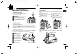
!IC-F50_F60 BIIS.qxd 03.9.12 8:49 AM 1 Page 1 (1,1) ACCESSORIES ACCESSORIES ■ Accessory attachments ï Jack cover Connect the supplied flexible antenna to the antenna connector. CAUTION! • NEVER HOLD by the antenna when carrying the transceiver. • Transmitting without an antenna may damage the transceiver. ï Battery pack q To attach the battery pack: Slide the battery pack on the back of the transceiver in the direction of the arrow (q), then lock it with the battery release button.
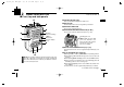
!IC-F50_F60 BIIS.qxd 03.9.12 8:49 AM 2 Page 3 (1,1) PANEL DESCRIPTION PANEL DESCRIPTION 2 ■ Front, top and side panels q VOLUME CONTROL [VOL] Turns power ON and adjusts the audio level. w e q r Speaker (See the following NOTE.) Microphone Function display (p. 6) i u t 2 w RED BUTTON The desired function can be assigned by your dealer. e ANTENNA CONNECTOR Connects the supplied antenna. r SPEAKER-MICROPHONE CONNECTOR [SP MIC] Connects the optional speaker-microphone. (p.
!IC-F50_F60 BIIS.qxd 2 03.9.12 8:49 AM Page 5 (1,1) PANEL DESCRIPTION ■ Front, top and side panels (Continued) u TRANSMIT/BUSY INDICATOR Lights red while transmitting; lights green while receiving a signal, or when the squelch is open. PANEL DESCRIPTION 2 ■ Function display q w e r t y 2 u i PTT SWITCH [PTT] ➥ Push and hold to transmit; release to receive. i q OUTPUT POWER INDICATOR Appears when Low 2 or Low 1 is selected.
!IC-F50_F60 BIIS.qxd 2 03.9.12 8:49 AM Page 7 (1,1) PANEL DESCRIPTION ■ Programmable function keys The following functions can be assigned to [P0], [P1], [P2], [P3], [Red], [ ] and [ ] programmable function keys. Consult your Icom dealer or system operator for details concerning your transceivers programming. If the programmable function names are bracketed in the following explanations, the specific switch used to activate the function depends on programming.
!IC-F50_F60 BIIS.qxd 2 03.9.12 8:49 AM Page 9 (1,1) PANEL DESCRIPTION C.TONE CHANNEL ENTER KEY Select the continuous tone channel using [CH Up]/[CH Down] keys to change the tone frequency/code setting after pushing this key for permanent operation. TALK AROUND KEY Turn the talk around function ON and OFF. • The talk around function equalizes the transmit frequency to the receive frequency for transceiver-to-transceiver communication.
!IC-F50_F60 BIIS.qxd 2 03.9.12 8:49 AM Page 11 (1,1) PANEL DESCRIPTION VOICE SCRAMBLER FUNCTION Push to toggle the voice scrambler function ON and OFF. COMPANDER KEY Push to toggle the compander function ON and OFF. The compander function reduces noise components from the transmitting audio to provide clear communication. USER SET MODE KEY ➥ Push and hold to enter user set mode. ■ Turning power ON q Rotate [VOL] to turn power ON.
!IC-F50_F60 BIIS.qxd 03.9.12 8:49 AM 3 Page 13 (1,1) CONVENTIONAL OPERATION CONVENTIONAL OPERATION ■ Call procedure ■ Receiving and transmitting When your system employs tone signalling (excluding CTCSS and DTCS), the call procedure may be necessary prior to voice transmission. The tone signalling employed may be a selective calling system which allows you to call specific station(s) only and prevent unwanted stations from contacting you.
!IC-F50_F60 BIIS.qxd 3 03.9.12 8:49 AM Page 15 (1,1) CONVENTIONAL OPERATION D Transmitting notes • Transmit inhibit function The transceiver has several inhibit functions which restrict transmission under the following conditions: - The channel is in mute condition (‘Inaudible’ condition; “ ” does not appear). - Channel is busy. - Un-matched (or matched) CTCSS is received. - The selected channel is a ‘receive only’ channel.
!IC-F50_F60 BIIS.qxd 3 03.9.12 8:49 AM Page 17 (1,1) CONVENTIONAL OPERATION D DTMF transmission If the transceiver has [DTMF Autodial] assigned to it, the automatic DTMF transmission function is available. Up to 8 DTMF channels are available. TO SELECT A TX CODE: q Push [DTMF Autodial]— a DTMF channel appears. w Push [ ]/[ ] to select the desired DTMF channel. e Push [DTMF Autodial] to transmit the DTMF code in the selected DTMF channel.
!IC-F50_F60 BIIS.qxd 03.9.12 8:49 AM 4 Page 19 (1,1) BIIS OPERATION BIIS OPERATION ■ Default setting ■ Receiving a call The following functions are assigned to each programmable switch as the default. Ask your dealer for details. q When an individual call is received; [P0]; Call : Push to transmit a 5-tone/BIIS call when the selected channel is a 5-tone or MSK channel, respectively.
!IC-F50_F60 BIIS.qxd 4 03.9.12 8:49 AM Page 21 (1,1) BIIS OPERATION BIIS OPERATION D Group call 4 D Displaying the received call record — Queue indication q When a group call is received; • Beeps sound. • “ ” appears and the mute is released. • The programmed text message (e.g.“ ”) and the calling station ID (or text) is displayed alternately, depending on the setting. • “ ” appears or blinks depending on the setting. The transceiver memorizes the calling station IDs for record.
!IC-F50_F60 BIIS.qxd 4 03.9.12 8:49 AM Page 23 (1,1) BIIS OPERATION BIIS OPERATION 4 ■ Transmitting a call Total of a 3 ways for code selection are available—selecting the call code from memory, entering the call code from the keypad and calling back from the queue channel record. D Calling back from the queue channel q While in the standby condition, push [P1] (Digital) for 1 sec. to enter queue memory channel selection mode. w Push [ ]/[ ] to select the desired record.
!IC-F50_F60 BIIS.qxd 4 03.9.12 8:49 AM Page 25 (1,1) BIIS OPERATION D Direct code entry q While in the standby condition, push [TX Code Enter] to enter the TX code edit mode. • Editable code digit blinks. BIIS OPERATION 4 ■ Receiving a message D Receiving a status message q When a status message is received; • Beeps sound. • The calling station ID (or text) and the status message is displayed alternately, depending on the setting. 4 w Push [TX Code Enter] to select the desired digit to be edited.
!IC-F50_F60 BIIS.qxd 4 03.9.12 8:49 AM Page 27 (1,1) BIIS OPERATION BIIS OPERATION 4 D Receiving an SDM D Received message selection q When an SDM is received; The transceiver memorizes the received messages for record. Up to 6 messages for status and SDM, or 95 character SDM’s can be memorized. The oldest message is erased when the 7th message is received. However, once the transceiver is powered OFF, all messages are cleared. • Beeps sound.
!IC-F50_F60 BIIS.qxd 4 03.9.12 8:49 AM Page 29 (1,1) BIIS OPERATION BIIS OPERATION ■ Transmitting a status 4 ■ Transmitting an SDM D General D General The status message can be selected with the programmed text, and the message text is also displayed on the function display of the called station. Up to 24 status types (1 to 24) are available, and the status messages 22 and 24 have designated meanings.
!IC-F50_F60 BIIS.qxd 4 03.9.12 8:49 AM Page 31 (1,1) BIIS OPERATION 4 ■ Position data transmission ■ Printer connection When the optional OPC-966 INTERFACE CABLE and a GPS receiver is connected to the transceiver, the position (longitude and latitude) data can be transmitted automatically. Ask your dealer or system operator for connection details.
!IC-F50_F60 BIIS.qxd 4 03.9.12 8:49 AM Page 33 (1,1) BIIS OPERATION 4 ■ Auto emergency transmission ■ BIIS indication When [Emergency Single (Silent)] or [Emergency Repeat (Silent)] is pushed, an emergency signal is automatically transmitted for the specified time period. The following indications are available for the BIIS operation on an MSK channel.
!IC-F50_F60 BIIS.qxd 03.9.12 8:49 AM 5 Page 35 (1,1) BATTERY CHARGING BATTERY CHARGING 5 ■ Battery charging ■ Caution Prior to using the transceiver for the first time, the battery pack must be fully charged for optimum life and operation. CAUTION! NEVER insert battery pack/transceiver (with the battery pack attached) with wet or soiled into the charger. This may result in corrosion of the charger terminals or damage to the charger. The charger is not waterproof and water can easily get into it.
!IC-F50_F60 BIIS.qxd 5 03.9.12 8:49 AM Page 37 (1,1) BATTERY CHARGING BATTERY CHARGING 5 ■ Optional battery chargers ï Regular charging with the BC-152 D For your convenience q Attach the BC-152 to a flat surface, such as a desk, if desired. w Connect the AC adapter (BC-147A/E*) as shown below. *Depending on version. e Insert the battery pack with/without the transceiver into the charger. • The charge indicator lights green. r Charge the battery pack approx.
!IC-F50_F60 BIIS.qxd 5 03.9.12 8:49 AM Page 39 (1,1) BATTERY CHARGING BATTERY CHARGING 5 ï AD-100 installation q Install the AD-100 desktop charger adapter into the holder space of the BC-119N/121N. w Connect the plugs of the BC-119N/121N to the AD-100 with the connector, then install the adapter into the charger with the supplied screws.
!IC-F50_F60 BIIS.qxd 5 03.9.12 8:49 AM Page 41 (1,1) BATTERY CHARGING BATTERY CHARGING 5 D Rapid charging with the BC-119N+AD-100 D Rapid charging with the BC-121N+AD-100 The optional BC-119N provides rapid charging of optional Li-Ion battery packs. The following are additionally required: • One AD-100 (purchase separately). • An AC adapter (may be supplied with BC-119N depending on version) or the DC power cable (OPC-515L/CP-17L).
!IC-F50_F60 BIIS.qxd 5 03.9.12 8:49 AM Page 43 (1,1) BATTERY CHARGING BATTERY CHARGING 5 ■ Optional battery case When using the optional battery case attached to the transceiver, install 5 × AA (R6) size alkaline batteries as illustrated at right. The BP-226 meets JIS waterproof specification grade 4. q Hook your finger under the latch, and open the cover in the direction of the arrow (q). (Fig.1) w Then, install 5 × AA (R6) size alkaline batteries. (Fig.2) • Install the alkaline batteries only.
!IC-F50_F60 BIIS.qxd 03.9.12 8:49 AM 6 Page 45 (1,1) SPEAKER-MICROPHONE ■ Optional HM-138 description Alligator type clip To attach the speaker-mic. to your shirt or collar, etc. SPEAKER-MICROPHONE 6 ■ Attachment Attach the connector of the speaker-microphone into the [SP MIC] connector on the transceiver and tighten the screw. 6 PTT switch Transmits while pushed Receives while released Microphone Speaker NEVER immerse the connector in water.
!IC-F50_F60 BIIS.qxd 03.9.12 8:49 AM 7 Page 47 (1,1) OPTIONS • BP-226 BATTERY CASE Battery case for 5 × AA (R6) alkaline cells. • BP-227 Li-Ion BATTERY PACK 7.2 V/1700 mAh Li-Ion battery pack. The same as supplied with the transceiver. BP-227 must be charged with the optional BC-152 or the BC-119N/121N. OPTIONS 7 • BC-121N MULTI-CHARGER + AD-100 CHARGER ADAPTER (6 pcs.) + BC-124 AC ADAPTER For rapid charging of up to 6 battery packs (six AD-100’s are required) simultaneously.
!IC-F50_F60 BIIS.qxd 03.9.12 8:49 AM Page 49 (1,1) A-6294H-1EX Printed in Japan © 2003 Icom Inc.