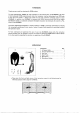
SECTION 1 PRECAUTIONS B INSTALLATION LOCATIONS. PREPARATIONS g *DONOR place in excessive ot humid torridity environments: » DO NOT: place near: radios o TV sets where un: wanted noise or signals may be received. « DO NOT place arn AL power supply. or the trans: caver or vice versa. W GROUNDING Ta prevent electrical shocks, TV L BCL and other problems; be sure 1o ground the transceiver thorough the GROUND TERMINAL.
#High sensitivity, high dynamic tangs. W COMPLETE UHF TRANSCEIVER w Compact size. RACKET, ACTOR operations. #Full break:in function. M OPTIONS AVAILABLE 1C-AGY AMPLIFIER UNIT UT:36 VOICE SYNTHESIZER UNIT: UT:34 TONE SQUELCH UNIT CT-18 SATELLITE INTERFACE UNIT CT-15. YAQUI ADAPTER £L.83 CW NARROW FILTER CRIB HIGH-STABILITY CRYSTAL UNIT The ABDICATE ‘RE amplifier uses a Tow: noise ‘Figure high gain; disk-type ‘Gasket (RSK121) for: UHF applications: | Also.
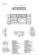
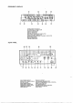
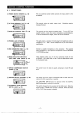
Y RF GAIN CONTROL [RE GAIN (p. 19) in SSB, CW modes: This control varies the gain of the RF stage when the transceiver i in receive mode. ‘Rotate clockwise for maximum gain. Aie ST [ ! 1858 and CW modes, the transceiver may. receive signals that arg. stronger than this levels shown on 'the rater! in EM mode: The: control makes the variable attenuate function noncontinuous: Tom 0 to 20dB when the transceiver is in receive mods. ZeW DELAY CONTROL [DELAY] (.
19 DATA SWITCH [DATA) TUNING CONTROL Q@ 29 TUNING STEP SELECTOR SWITCH {18t = G)MHz TUNING STEP SWITCH Ia Hz] % go‘!’ = ST DIAL LOCK SWITCH T Lock] §: : < SHALL CHANNEL SWITCH [CALL FREQUENCY TRANSFER SWITCH [M» VFO] i(p. 34) s @ Push this switch to-use operating modes such as PACKET or ACTOR communications: which require rapid receive and transmit switching: times: Rotate this control clockwise 1o increase frequency. numbers and counterclockwise to decrease thee.
5.5 ACCRA) SOCKET Various signals: are available from ‘the ACCUSE) SOCKET such as INFORMATION receiver output, modulator input, T/R changeover, ete. DESCRIPTION connection 2 GND Ground. 3 SEND switches: 1o the: transmit mode when this terming i grounded vig the (X BITCH fon the 'REAR ‘@j \5‘ PANEL. 1t can also. be grounded by fi? RO connecting the transceiver eternal computer. @ i 4 MOD Connected: in : the : modulator stage.
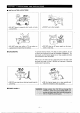
SECTION 6 GENERAL OPERATION 6 -1 INITIAL SETTINGS After all INSTALLATION instructions have been followed in SECTION 4. including connecting am antenna. system . set the con. trolls and switches as indicated below: the DC output voltage If sing ' non-COM AC power supply. 2) Ary antenna must:be connected to'the ANTENNA CONNECTOR: . CAUTION 31 A ground: connection: must: be: made through the \GROUND. TERMINAL {1} Front panel switch and control settings \ = POSITION | SWITCHBOARD O POWER OFF {Out) RE GAIN @ AR
2 Adjust (RE CONTROLLING: st e san * FM REPEATER OPERATION T Pisa [DUP] SWITCH & o 2} Sweeten to tragicomic Push PITT] e SWITCH 63 558 OPERATION {1} SS8 receiving 1) i Set the! switches 'and controls a8 shown: in SECTION 6 -1 2} Euro power ON.
45 Adjust [REP] CONTROL: & o * SPEECH COMPRESSOR OPERATION: Gore Age N 6-4 CW OPERATION {1} CW receiving 1) Seethe switcher “and: controls ey dhows. in SECTION 1 2} Tito power ON. 3 Push [OVARIAN] SWITCH. A Push JAG] SWITCH N, i PARENT Stadium LAPEL GAIN-CONTROL GARBLE Tem [CONTROLLER Ay o 23 Tue TUNING CONTROL 5 @ 4) Adjust the [RF PWR] CONTROL to 3 suitable output” power feels The talk power can be increased over Tong distances by using this function.
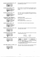
30 Ministrant, Transfix frequency 9 OVER: Y3 2086 13 DUPE: * Receive frequency Venom 4IHEOOE 3 A Push [CHK] SWITCH, S} Push DURER T SWITCH 1o Manuel dhe ' duplex ride. 3 43gaooo n3 T DUPE" disappears {2¥ Duplex operation using contents of VFO A sad VEO B {SPLIT operation} 1} Bet VED A mode and program 439.0500MHz.
71-7 DATA SWITCH OPERATION 7.8 PASS BAND TUNING {PBT) OPERATION This ‘switch: allows yolks 1o freely. operate digital communications such as ACTOR or PACKET with time delay. «The: lockup time s approximately 8 milliseconds when using the [FATAL SWITCH. » The [FATAL SWITCH does not function in CW mode; 1} Connect the terminal Unit 1o the 10A7BA/E properly. 2} Defect a mode switch and push the [DATA] SWITCH. * "DATA" aspersion the FREQUENCY DISPLAY.
7-11 MICROPHONE UR/DOWN This up/down. function s useful for. changing the operating noncooperation quench ‘when: using the: VEQ made or when Using the MEMORY. CHANNEL made. Microphone UP/DOWN ON:OFF SWITCHES: UPTOWN ON-OFF «OFE: The [UP] SWITCH and [DN] SWITCH moniker microphone SWITCH are disabled o eliminate the chance of accidental frequency immemorial channel changes.
SECTION 8 MEMORY AND SCANNING OPERATION 8-1 VFO A AND VEO B SELECTION The 1C475A/k has pitying-ning memory: channels: Dre frequency; the ‘operating mode: the sub audible tone frequency. VFOQA/B and the duplex edition may: be: assigned: to each memory: channel whether: the transceivers in VY EO mode ar MEMORY: CHANNEL: mode.: 1EVEQ Ac and VFO B can be selected by pushing: the 1VFQ] SWITCH alternately) 2} The: parameters in: VEQ Ac and VERB Gan be made the same by pushing the [A =B SWITCH.
8:-3 MEMORY DATA TRANSFER 0! Nu Yea, o 5 e ‘Q‘? # 1} When: the transceiver Is in VFO mode, the frequency and rides stored in the: memory: channel displayed are: transferred to the selected VRO, 2) When:the: transceiver s fin MEMORY CHANNEL | o the frequency and mode are transferred to the VEO side immediately. before transferring o MEMORY. CHANNEL L made VFQ mode: Push [MOVE] 433800088 99 0D | 4355500 gg i Push M »VEQ] MEMO Y CHANNEL mods: and [FREQ) VEQ mode 4388000 (B L ugppgann ! 8:4.
9:2 ADJUSTMENTS (1) Brake adjustment 12} Display fight dimmer adjustment 13} Boer sound level adjustment The TUNING CONTROL: tension: may ba adjusted 10 the operator's preference. The screw adjustment is located on the Bosom side oF the: transceiver cabinet below the TUNING CONTROL: The method for adjustment 15 as follows? 1} Rotate ‘the TUNING CONTROL contentiously and smoothie in redirection; 2} Adjustment brake adjustment screw: either Clifford tighter tension or: COW for loser tension as desired.
11247134 TONE SQUELCH UNIT 11-NUT-36 3 VOICE SYNTHESIZER UNIT 11-4FL83 CW NARROW FILTER 115 CR-84 HIGH-STABILITY. CRYSTAL UNIT The UT-34: TONE SQUELCH UNIT provides vou with interference: free: communication with other stations skipped: with ‘& Tone Squelch: System: o The unit should be instated: . the designated:spot behind the: internal speaker on the PA UNIT, 1) :Remove both the topi and bottom covers: 2} Remove the PA UNIT. Q) install ‘the UT:34 and ‘connect ‘P48.