INSTRUCTION MANUAL HF/VHF/UHF ALL MODE TRANSCEIVER i7000
IMPORTANT READ THIS INSTRUCTION MANUAL CAREFULLY before attempting to operate the transceiver. EXPLICIT DEFINITIONS WORD DEFINITION R WARNING Personal injury, fire hazard or electric shock may occur. SAVE THIS INSTRUCTION MANUAL. This CAUTION manual contains important safety and operating instructions for the IC-7000. NOTE FOREWORD We understand that you have a choice of many different radios in the market place.
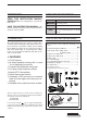
ILLUSTRATIONS Front panel !6 @4 @3 @2 @1 @0 !9 !8 !7 q w e !5 t yu i !0 !1 !2 o !4 !3 r HM-151 ⁄3 z SPCH /LOCK TUNER /CALL XFC V/M MW F-1 F-2 x c v . , 1.8 10 b ⁄2 ⁄1 21 50 1 4 7 . 3.5 14 24 2 5 8 144 0 7 18 28 3 MODE 6 FIL 9 GENE 430 CE ⁄0 Mic element m n F-INP ENT The front panel and HM-151’s panel descriptions are descrived on pages 1 to 4, and on page 9, respectively (see the Chapter 1 ‘PANEL DESCRIPTION’ for more details).
■ Front panel ■ Microphone (HM-151) q AF GAIN CONTROL [AF] (inner control; p. 33) z SPCH/LOCK KEY [SPCH/LOCK] (p. 34, 37) w RF GAIN CONTROL/SQUELCH CONTROL [RF/SQL] (outer control; p. 35) x PTT SWITCH [PTT] (p. 37) e POWER KEY [PWR] (p. 25) r FRONT PANEL LATCH (p. 16) t PASSBAND TUNING/M-ch/RIT CONTROLS [PBT/M-ch/RIT] (pgs. 73, 77, 86, 100, 104) y TWIN PBT (M-ch/RIT) INDICATOR (pgs. 73, 77, 86, 100) v TRANSMIT INDICATOR (p. 37) b KEYPAD (pgs. 28, 29) n FILTER SELECTION [FIL] (p.
PRECAUTIONS R WARNING RF EXPOSURE! This device emits Radio Frequency (RF) energy. Extreme caution should be observed when operating this device. If you have any questions regarding RF exposure and safety standards please refer to the Federal Communications Commission Office of Engineering and Technology’s report on Evaluating Compliance with FCC Guidelines for Human Radio Frequency Electromagnetic Fields (OET Bulletin 65).
TABLE OF CONTENTS IMPORTANT …………………………………………i-1 FOREWORD ………………………………………… i-1 EXPLICIT DEFINITIONS …………………………… i-1 SUPPLIED ACCESSORIES …………………………i-1 ILLUSTRATIONS ……………………………………i-2 ■ Front panel ……………………………………… i-3 ■ Microphone (HM-151) ………………………… i-3 PRECAUTIONS ………………………………………ii TABLE OF CONTENTS …………………………… iii 1 PANEL DESCRIPTION ………………… 1–14 ■ Front panel ………………………………………… 1 ■ Multi-function keys ……………………………… 5 D Menu M-1 functions …………………………… 5 D Menu M-2 functions …………………………… 5 D Menu M-3 function
TABLE OF CONTENTS 4 Paddle Polarity ……………………………… 50 5 Keyer Type ………………………………… 50 6 MIC U/D Keyer (HM-103) ………………… 50 D Paddle operation from [MIC] connector …… 50 ■ Operating RTTY (FSK) ………………………… 51 D Convenient functions for receive …………… 52 D RTTY reverse mode ………………………… 53 D Twin peak filter ………………………………… 53 D Functions for the RTTY decoder indication… 54 D Setting the decoder threshold level ………… 54 D RTTY decode set mode ……………………… 55 1 RTTY Decode USOS ……………………… 55 2 RTTY Decode New Line Code …………… 5
TABLE OF CONTENTS D Selecting a memory channel using the memory channel list……………… 103 D Setting a memory channel as a select memory ………………………… 104 D Selecting a memory bank ………………… 104 D Memory names ……………………………… 105 ■ Memory clearing ……………………………… 106 D Memory clearing using the memory channel list……………… 106 ■ Frequency transferring………………………… 107 D Transferring in VFO mode ………………… 107 D Transferring in memory mode ……………… 108 ■ Memo pads …………………………………… 109 D Writing frequencies and operating modes into memo
TABLE OF CONTENTS 17 Tuner (Auto Start) ………………………… 130 18 Tuner (PTT start) …………………………… 131 19 [TUNER] Switch …………………………… 131 20 VSEND Select ……………………………… 131 21 SPEECH Level …………………………… 131 22 SPEECH Language ……………………… 131 23 SPEECH Speed …………………………… 131 24 SPEECH S-Level ………………………… 132 25 SPEECH [MODE] Switch ………………… 132 26 Memopad Numbers ……………………… 132 27 SCAN Speed ……………………………… 132 28 SCAN Resume …………………………… 132 29 MAIN DIAL Auto TS ……………………… 132 30 HM-151 [F-1] ……………………………… 133 31 HM-151 [F-2] ……………………
1 PANEL DESCRIPTION See the illustration of the Front panel on page i-2. ■ Front panel q AF GAIN CONTROL [AF(SET)] (inner control; p. 33) ➥ Rotate to vary the audio output level from the speaker or headphones. Audio output increases • When functioning as squelch control (RF gain is fixed at maximum.) Noise squelch threshold (FM mode) Noise squelch (FM mode) S-meter squelch threshold S-meter squelch Squelch is open. Audio outut decreases Push momentarily to enter the set mode menu.
PANEL DESCRIPTION ✔ What is the PBT control? PBT electronically narrows the IF passband width to reject interference. This transceiver uses DSP to implement PBT. ➥ While M-ch/RIT is selected: ● Rotate the inner control to select a memory channel number (p. 100). ● Push and hold inner control for 1 sec. to turn the RIT/∂TX mode ON (pgs. 73, 86). Z(MENU/GRP)] to exit the RIT/∂TX mode. • Push [Z ● While the RIT/∂TX mode is OFF: Rotate outer control to select a memory bank (p. 104).
1 PANEL DESCRIPTION !0 MANUAL NOTCH KEY [MNF/ADJ] (p. 81) ➥ Push momentarily to turn the manual notch function ON and OFF in SSB, CW and AM modes. •“ ” appears on the display when the function is activated. ➥ Push and hold for 1 sec. to enter the manual notch filter set mode. !5 MAIN DIAL TENSION LATCH Selects the main dial drag. • Three positions are available. The upper setting turns on clicks as the dial is turned. !6 HEADPHONE JACK [PHONES] (p. 18) Accepts headphones with 8–16 Ω impedance.
PANEL DESCRIPTION !9 TUNING STEP KEY [TS] (pgs. 30–32) ➥ While in SSB/CW/RTTY modes, push momentarily to turn the programmable tuning step ON and OFF. While in AM/FM/WFM modes, push momentarily to toggle the programmable tuning step and 1 MHz quick tuning step. • While the programmable tuning step indicator is displayed, the frequency can be changed in the programmed kHz step size.
1 PANEL DESCRIPTION ■ Multi-function keys D Menu M-2 functions D Menu M-1 functions SPL A/B FIL XFC F-1 F-2 F-3 F-4 SPLIT OPERATION ➥ Push momentarily to toggle the split function ON and OFF. (p. 89) SPL F-1 •“ ” and transmit frequency appear when the split function is ON. ➥ Push and hold for 1 sec. to turn the quick split function ON. (p. 90) • The offset frequency must be programmed in advance using the miscellaneous (others) set mode. (pgs.
PANEL DESCRIPTION DURING FM/WFM OPERATIONS: VOX DUP TON 9600 F-1 F-2 F-3 F-4 BREAK-IN FUNCTION (p. 85) ➥ Push momentarily to select semi break-in, full break-in (QSK) and break-in OFF. BRK F-1 VOX FUNCTION (p. 83) ➥ Push momentarily to toggle the VOX function ON and OFF. VOX F-1 • The VOX gain, ANTI-VOX and VOX delay can be set in VOX set mode.
1 PANEL DESCRIPTION D Menu S-1 functions DTM DURING SSB/AM OPERATION: VO F-1 MET VSC F-3 F-4 F-2 DTMF OPERATION Push to enter DTMF memory mode. (p. 67) F-4 • The DTMF send menu or DTMF root menu DTMF 1st appears depending on the “D Menu” setting in the miscellaneous (others) set mode. (p.
PANEL DESCRIPTION D Menu S-3 functions 1 D Menu G-1 (Scope) functions MW MPW MPR F-1 F-2 F-3 SPN HLD FIX SPD F-1 F-2 F-3 F-4 F-4 MEMORY WRITE (pgs. 101, 102) Push and hold for 1 sec. to store the displayed VFO frequency and operating F-1 mode into the selected memory channel. MW MEMO PAD WRITE (p. 109) Push to store the displayed VFO frequency and operating mode into a memo F-2 pad. MPW SWEEP STEPS (pgs. 70, 71) ➥ Push momentarily to change the sweep step size.
1 PANEL DESCRIPTION See the illustration of the HM-151 on page i-2. ■ Microphone (HM-151) z SPCH/LOCK KEY [SPCH/LOCK] ➥ Push momentarily to have the frequency, etc. announced by the speech synthesizer. (p. 34) • The parameters to be announced can be selected in the miscellaneous (others) set mode. (p. 132) ➥ Push and hold for 1 sec. to toggle the microphone lock function ON and OFF. (p. 37) x PTT SWITCH [PTT] (p. 37) Push and hold to transmit; release to receive.
PANEL DESCRIPTION 1 D Microphone connector MICROPHONE CONNECTOR INFORMATION Rear panel view CAUTION: DO NOT short pin 1 to ground as this can damage the internal 8 V regulator. 1 87654321 HM-151 q +8 V DC output w Frequency up/down e M8V SW r PTT t GND (Microphone ground) y Microphone input u GND i DATA IN HM-103 q +8 V DC output w Frequency up/down e M8V SW r PTT t GND (Microphone ground) y Microphone input u GND i Squelch switch • When HM-151 is connected PIN NO.
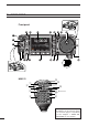
1 PANEL DESCRIPTION ■ Rear panel q w e KEY ACC DATA rt y ui o MIC GND !0 ANT2 ANT1 DC 13.8V !2 q ELECTRONIC KEYER JACK [KEY] (p. 22) Accepts a paddle to activate the internal electronic keyer. u RTTY JACK [RTT Y] (p. 23) Connects an external terminal unit for RTTY (FSK) operation. • Selection between the internal electronic keyer and straight key operation can be made in the keyer set mode. (p. 50) • The keying polarity, mark/shift frequencies and etc. can be selected in quick set mode (p.
PANEL DESCRIPTION 1 D DATA socket DATA 1 PIN No. NAME 1 DATA IN 2 GND Common ground for DATA IN, DATA OUT and AF OUT. 3 PTT P PTT terminal for packet operation. Connect to ground to activate the transmitter. When grounded, microphone input (pin 6) of [MIC] connector will be disconnected. 2 3 4 5 4 6 5 DESCRIPTION Input terminal for data transmit. (1200 bps: AFSK/9600 bps: G3RUH, GMSK) DATA OUT Data out terminal for 9600 bps operation only.
1 PANEL DESCRIPTION • When connecting the ACC conversion cable (OPC-599) 13 9 10 11 12 5 6 7 8 1 2 3 4 Connect to ACC socket ACC 1 4 1 ACC 2 2 5 4 3 8 6 1 6 7 q FSKK w GND e HSEND r MOD t AF y SQLS u 13.8 V i ALC 2 5 3 7 q8V t ALC w GND y VSEND u 13.8 V e HSEND r NC (BAND*) * See p. 140 for details ■ Function display !4 !3 !2 !1 q w e !0 @4 o i u y t r q FREQUENCY READOUT Shows the operating frequency. w METER READOUTS ➥ Shows received signal strength while receiving.
PANEL DESCRIPTION !1 SPLIT INDICATOR (pgs. 89, 90) Appears during split operation. !2 IF FILTER INDICATOR (p. 75) Shows the selected IF filter number. 1 !7 MULTI-FUNCTION SCREEN Shows the screens for the multi-function meter, simple band scope, SWR meter, memory channel, voice recorder, memory keyer, DTMF memory encoder, RTTY decoder, IF filter selection or popup indication, etc. !3 PASSBAND WIDTH INDICATOR (p.
2 INSTALLATION AND CONNECTIONS ■ Unpacking ■ Antenna connection After unpacking, immediately report any damage to the delivering carrier or dealer. Keep the shipping cartons. For radio communications the antenna is of critical importance for output power and sensitivity. Use wellmatched 50-ohm antennas and coaxial feedline. An SWR (standing wave radio) of 1.5:1 or lower is recommended when transmitting.
INSTALLATION AND CONNECTIONS 2 ■ Installation D Single body mounting MB-62 (optional) D Stand Spring washer Nut To raise the stand: With the transceiver upside down, pull the stand towards the rear panel and then upwards, as illustrated below. Supplied with the MB-62* then up Pull back Flat washer 2 *CAUTION: Non-supplied screws (longer than 8 mm) may damage the internal units. D Front panel separation q While pulling the front panel latch towards you, slide the front panel to the left (fig. 1).
2 INSTALLATION AND CONNECTIONS ■ Required connections MICROPHONE (p. 10) GROUND (p. 15) Use the heaviest gauge wire or strap available and make the connection as short as possible. STRAIGHT KEY HM-151 Grounding prevents electrical shocks, TVI and other problems. RTTY TERMINAL UNIT (p. 23) KEY ACC MIC DATA GND ANT2 ANT1 DC 13.8V 2 m/70 cm ANTENNA DC POWER SUPPLY (p.19) AC outlet A DC power supply 13.
INSTALLATION AND CONNECTIONS 2 ■ Advanced connections HEADPHONES 2 OPC-589 (p. 150) DATA SOCKET (p. 12) 6-pin mini DIN socket to connect to a TNC, etc. for packet operation. or SPEAKER VIDEO OUT to [VOUT] jack SM-20 Vout GND 3.5(d) mm DESKTOP (p. 149) MICROPHONE ACC SOCKET (p. 12) KEY ACC Selectable with the [PHONE/SPEAKER] switch on the back of the front panel. MIC DATA GND ANT2 ANT1 DC 13.8V REMOTE (p. 142) Used for computer control and transceive operation. EXTERNAL SPEAKER (p.
2 INSTALLATION AND CONNECTIONS ■ Power supply connections Use the DC power supply with a 25 A capacity when operating the transceiver with AC power. Refer to the diagrams below. CAUTION: Before connecting the DC power cable, check the following important items. Make sure: • The [POWER] switch is OFF. • Output voltage of the power source is 12–15 V. • DC power cable polarity is correct.
INSTALLATION AND CONNECTIONS 2 ■ External antenna tuners CONNECTING THE AH-4 Coaxial cable IC-7000 ANT1 Long wire or optional AH-2b (from the AH-4) AH-4 Ground Ground 2 CONNECTING THE AT-180 ACC cable supplied with the AT-180 HF to 6 m antenna Coaxial cable supplied with the AT-180 [ACC] [ANT1] [ANT] AT-180 [ACC] Either of the two external connectors IC-7000 Ground Ground [TRANSCEIVER] • Turn the IC-7000’s power OFF when connecting the AT-180, otherwise, the CPU may malfunction and the
2 INSTALLATION AND CONNECTIONS ■ Linear amplifier connections Use the [ANT1] connector when connecting an HF/50 MHz linear amplifier.
INSTALLATION AND CONNECTIONS 2 ■ Connections for CW Keyer set mode (p. 49) [KEY] Rear panel Keyer set mode setting Paddle polarity Keyer Type Normal ELEC-KEY N o rma l [ACC] Paddle polarity Keyer Type 13 9 10 11 12 5 6 7 8 1 2 3 4 For no break-in operation: Connect an external switch such as a foot switch; or use the RTTY SEND terminal for all bands. (See p.
2 INSTALLATION AND CONNECTIONS ■ Connections for RTTY D Connections for RTTY (FSK) Rear panel [ACC] [RTTY] [EXT SP] 2-conductor 1/8˝ plug TNC or PC interface for the RTTY software Personal computer AF GND SEND FSKK GND 3-conductor 1/8˝ plug (supplied) Rear panel view SQL*1 (light green) FSKK (black) AF out (light blue) MSEND*2 GND (red) 13 9 10 11 12 5 6 7 8 1 2 3 4 *1Connect SQL line when required. *2eHF/50 MHz: orange u144/430 MHz: purple Colors refer to the wires in the supplied ACC cable.
INSTALLATION AND CONNECTIONS 2 ■ Connections for packet, SSTV or PSK31 D When connecting to [DATA] socket TX AUDIO DATA IN q w GND GND r DATA OUT PTTP e *1Connect SQL line when required.
3 BASIC OPERATION ■ When first applying power (CPU resetting) Before first applying power, make sure all connections required for your system are complete by referring to Chapter 2. Then, reset the transceiver using the following procedure. [Y] [PWR] [Z] Resetting CLEARS all programmed contents in memory channels and returns default values in set mode. q Make sure the transceiver power is OFF. Y(BAND)] and w While pushing and holding [Y Z(BAND)], push [PWR] to start resetting.
BASIC OPERATION 3 ■ VFO description VFO is an abbreviation of Variable Frequency Oscillator, and traditionally refers to an oscillator. The IC-7000 VFO is somewhat different. The VFO display of the IC-7000 acts like a computer’s window and can show one frequency and one operating mode. Select MODE KEY VFO Change You can call up a desired frequency to the VFO with the memo pad-read key (p. 110) or the memory transfer function (p. 107).
3 BASIC OPERATION ■ VFO operation D Selecting VFO A/VFO B q Select M-1. Either “ ” or “ ” appears. Menu group selection Push [MENU/GRP] for 1 sec. Selection from: M, S or G(Graphic) Menu selection (Example: M) Push [MENU/GRP] momentarily. Selection from: M-1, M-2 or M-3 Either Y or Z w Push [F-2 A/B] to toggle VFO A or VFO B. [MENU/GRP] [F-2] D VFO equalization q Select M-1. w Push and hold [F-2 A/B ] for 1 sec. to set the undisplayed VFO frequency and mode to those of the displayed VFO.
BASIC OPERATION 3 ■ Selecting an operating band The triple band stacking register provides 3 memories in one band. 3 sets of frequency and operating mode on each band are automatically stored when used. HM-151 SPCH /LOCK 1.8 10 21 50 1 4 7 . TUNER /CALL 3.5 14 24 2 5 8 144 0 XFC V/M MW F-1 F-2 7 18 28 3 MODE 6 FIL 9 GENE 430 CE If a band key (on the HM-151) is pushed once, the last used frequency and operating mode on that band are called up.
3 BASIC OPERATION ■ Frequency setting The transceiver has several tuning methods for convenient frequency tuning. D Tuning with the main dial [Y] [Z] Y(BAND)] or [Z Z(BAND)] to select the desired q Push [Y band. Or push the desired band key on the microphone 1–3 times. • Three different frequencies can be selected on each band with the microphone’s band key. (See previous page “Using the band stacking register.”) [DIAL] HM-151 SPCH /LOCK 1.8 10 3.
BASIC OPERATION 3 D Programmable tuning step The operating frequency can be changed in steps of (0.01 (AM/FM/WFM only), 0.1, 1, 5, 9, 10, 12.5, 20, 25 or 100 kHz selectable) for quick tuning. Appears [TS] [DIAL] q Push [TS] momentarily to turn the programmable tuning function ON. • “Z” appears when the programmable tuning function is ON. Programmable tuning step indicator w Rotate [DIAL] to change the frequency in programmed kHz steps. e Push [TS] again to turn the programmable tuning function OFF.
3 BASIC OPERATION D Selecting 1 Hz or 10 Hz step (SSB/CW/RTTY only) When neither the quick tuning step or programmable tuning step “Z” appear, rotating [DIAL] changes the frequency in increments of 1 or 10 Hz. These tuning steps are only available in SSB, CW and RTTY modes. [MODE] [TS] [DIAL] q Select SSB, CW or RTTY mode if necessary. w Push and hold [TS] for 1 sec. to toggle between the 1 Hz and 10 Hz step settings.
BASIC OPERATION 3 • [TS] switch flow chart SSB/CW/RTTY modes Push Any mode Push FM/WFM/AM modes Appears momentarily momentarily Programmable step tuning SSB/CW/RTTY modes (0.1 kHz –100 kHz) FM/WFM/AM modes (0.01 kHz–100 kHz) 10 Hz tuning Push Appears 1 sec. 1 sec. Push 1 MHz tuning 1 sec. momentarily 3 1 Hz tuning Appears Selectable for each mode. D 1⁄4 tuning function (CW/RTTY only) While operating in CW/RTTY, the 1⁄4 tuning function is available for critical tuning.
3 BASIC OPERATION D Auto tuning step function When rotating the tuning dial rapidly, the tuning speed accelerates automatically as selected. q Push [AF(SET)] momentarily to enter the set mode menu. w Push [F-4 OTH] to enter the miscellaneous (others) set mode. MAIN DIAL e Push [F-1 ≤] or [F-2 ≥] to select “M Auto TS.” r Rotate [DIAL] to select the desired tuning speed from high, low and OFF. [AF] [MENU/GRP] [F-1] [F-2] [F-4] • HIGH: Approx. 5 times faster • LOW : Approx.
BASIC OPERATION 3 ■ Operating mode selection The following modes are available in the IC-7000: SSB (LSB/USB), CW, CW-R (CW reverse), RTTY, RTTY-R (RTTY reverse), AM, FM and WFM (receive only). OPERATING MODE SELECTION To select the desired mode of operation, push [MODE] one or more times, then push [MODE] for 1 sec., if necessary. See the diagram at right for the order of selection.
3 BASIC OPERATION ■ Squelch and receive (RF) sensitivity [RF/SQL] adjusts the RF gain and squelch threshold level. The squelch removes noise output from the speaker (closed position) when no signal is received. [RF/SQL] • The squelch is particularly effective for FM. It is also available for other modes. • The 12 to 1 o’clock position is recommended for any setting of the [RF/SQL] control.
BASIC OPERATION 3 ■ Meter function The transceiver has 4 transmit meter functions for your convenience. Select the desired meter with the [F-3 MET] in the S-1 display. DISPLAY INDICATION [MENU/GRP] Po Indicates the relative RF output power in %. SWR Indicates the SWR on the transmission line. ALC Indicates the ALC level. When the meter movement shows the input signal level exceeds the allowable level, the ALC limits the RF power. In such cases, reduce the MIC gain setting (see p.
3 BASIC OPERATION ■ Lock functions The lock function can only be activated when displaying frequency, not in set mode or memory channel listing display. D Dial lock function The dial lock function prevents accidental change caused by [DIAL]. ➥ Push and hold [SPCH/LOCK] for 1 sec. to turn the dial lock function ON and OFF. •“ ” indicator appears while the dial lock function is activated. Appears [SPCH/LOCK] D Microphone lock function This function locks microphone keypads.
BASIC OPERATION 3 D Setting output power q Push [AF(SET)] momentarily to enter the set mode menu. w Push [F-1 QS] to enter the quick set mode. RF Power.” e Push [F-1 Y] or [F-2 Z] to select “R r Rotate [DIAL] to set the desired output setting. [AF] • Output power is displayed in 1% steps (0% to 100%). Z(MENU/GRP)] to exit quick set mode.
4 RECEIVE AND TRANSMIT ■ Operating SSB q Push [ Y(BAND)]/[ Z(BAND)] to select the desired band or push a band key on the HM-151. w Push [MODE] momentarily or push and hold for 1 sec. to select LSB or USB mode. [AF] [MODE] [TX] indicator [Y] • Below 10 MHz LSB is automatically selected; above 10 MHz USB is automatically selected. e Rotate [DIAL] to tune in a desired signal. [Z] • The S-meter indicates received signal strength when signal is received.
RECEIVE AND TRANSMIT 4 D Convenient functions for transmit • Transmit quality monitor (p. 87) ➥ Push [AF(SET)], then [F-4 OTH] to enter the miscellaneous (others) set mode. Select an item with [F-1 ≤]/[F-2 ≥], then rotate [DIAL] to turn the monitor function ON and OFF. • VOX (voice operated transmit) (p. 83) M-3” is selected, push [F-1 VOX] to turn ➥ While “M the VOX function ON and OFF. • Push and hold [MENU/GRP] for 1 sec. once or twice to select the menu group M.
4 RECEIVE AND TRANSMIT ■ Operating CW q Connect a paddle or straight key as on page 22. Y(BAND)]/[Z Z(BAND)] to select the desired w Push [Y band or push a band key on the HM-151. e Push [MODE] momentarily to select CW mode. [AF] [MODE] [TX] indicator [Y] • After CW mode is selected, push and hold [MODE] for 1 sec. to toggle between CW and CW-R modes. r Rotate [DIAL] to tune in a desired signal with the desired tone frequency. t Rotate [AF] to set audio to a comfortable listening level.
RECEIVE AND TRANSMIT 4 D Convenient functions for receive • Preamp and attenuator (p. 72) ➥ Push [P.AMP/ATT] momentarily to turn the preamp ON or OFF. •“ ” appears when the preamp is set to ON. ➥ Push [P.AMP/ATT] for 1 sec. to turn the attenuator ON. • Push [P.AMP/ATT] momentarily to turn the attenuator OFF. •“ ” appears when the attenuator is set to ON. • Twin PBT (passband tuning) (p. 77) ➥ Push [PBT/M-ch/RIT] (switch) momentarily once or twice to select the twin PBT ON or OFF (M-ch RIT).
4 RECEIVE AND TRANSMIT D CW reverse mode The CW-R (CW Reverse) mode receives CW signals on the reverse sideband like that of LSB and USB modes. [MODE] Use when interference is near the desired signal and you want to change the interference tone. q Push [MODE] momentarily several times to select CW mode. w Push and hold [MODE] for 1 sec. to select CW or CW-R mode. • Receive audio tone response 600 Hz • Check the interference tone. 600 Hz Push for 1 sec.
RECEIVE AND TRANSMIT 4 D CW pitch control The received CW audio pitch and monitored CW audio pitch can be adjusted to suit your preferences (300 to 900 Hz) without changing the operating frequency. [AF] q When CW (CW-R) mode is selected, enter the quick set mode. • Push [AF(SET)] momentarily to enter the set mode menu. • Push [F-1 QS] to enter the quick set mode. CW w Push [F-1 ≤] or [F-2 ≥] several times to select “C Pitch ,” then rotate [DIAL] to set the desired pitch.
4 RECEIVE AND TRANSMIT ■ Electronic CW keyer The IC-7000 has a number of convenient functions for the electronic keyer that can be accessed from the memory keyer menu. [MODE] [MENU/GRP] [F-1] [F-2] [F-3] [F-4] [DIAL] q Push [MODE] to select CW mode. w Select S-1. (See right page.) e Push [F-2 KEY] to enter the keyer send menu. Z(MENU/GRP)] to select the keyer root menu. r Push [Z t Push one of the multi-function keys ([F-1] to [F-4]) to select the desired menu. See the diagram below.
RECEIVE AND TRANSMIT 4 Menu group selection Push [MENU/GRP] for 1 sec. Selection from: M, S or G(Graphic) Menu selection (Example: S) Push [MENU/GRP] momentarily. Selection from: S-1, S-2 or S-3 Either Y or Z D Memory keyer send menu Pre-set messages can be sent using the memory keyer send menu. Contents of the memory keyer are set using the edit menu. • Transmitting q Select CW mode with [MODE]. w Set the break-in function ON (p. 85).
4 RECEIVE AND TRANSMIT D Editing a keyer memory The contents of the memory keyer memories can be set using the memory keyer edit menu. The memory keyer can memorize and re-transmit 4 CW sequences for often-used CW messages, contest number, etc. Total capacity of the memory keyer is 55 characters per memory channel. • Programming contents q Push [MODE] to select CW mode. w Select S-1. • Push and hold [MENU/GRP] for 1 sec. once or twice to select the menu group S.
RECEIVE AND TRANSMIT 4 D Contest number set mode This menu is used to set the contest (serial) number and incrementing trigger channel, etc. [MODE] • Setting the contact (serial) number Contact number can be automatically transmitted from one of the memory keyer channels. The Morse cut numbers can be used as the contact numbers. The maximum number for contact numbers is 9999. q Select CW mode with [MODE]. w Select S-1. [MENU/GRP] [F-1] [F-2] [F-3] [F-4] • Push and hold [MENU/GRP] for 1 sec.
4 RECEIVE AND TRANSMIT D Keyer set mode This set mode is used to set the memory keyer repeat time, dash weight, paddle specifications, keyer type, etc. • Setting the electronic keyer q Select CW mode with [MODE]. w Select S-1. • Push and hold [MENU/GRP] for 1 sec. once or twice to select the menu group S. • Push [MENU/GRP] momentarily one or more times to select the menu S-1. [MODE] Z(MENU/GRP)] to select the e Push [F-2 KEY] then [Z keyer root menu.
RECEIVE AND TRANSMIT 4 D Keyer set mode (continued) 3 Rise Time This item sets the envelop rise time during which the output power reaches the set transmit power. • 2, 4, 6, or 8 msec. can be selected. • Push and hold [F-4 DEF] for 1 sec. to select a default setting. (default: 4 sec.) • About rise time Key action Tx Rx Set Tx power level Tx output power 0 Rise time Time 4 Paddle Polarity This item sets the paddle polarity. • Normal and reverse polarity can be selected.
4 RECEIVE AND TRANSMIT ■ Operating RTTY (FSK) When using your RTTY terminal or TNC, consult the manual that comes with the RTTY terminal or TNC. [AF] [MODE] [TX] indicator Z(BAND)] to select the desired Y(BAND)]/[Z q Push [Y band or push a band key on the HM-151. w Push [MODE] momentarily to select RTTY mode. [Y] • After RTTY mode is selected, push and hold [MODE] for 1 sec. to toggle between RTTY and RTTY-R modes. [Z] e Display the RTTY decoder screen. • Push and hold [MENU/GRP] for 1 sec.
RECEIVE AND TRANSMIT 4 D Convenient functions for receive • Preamp and attenuator (p. 72) ➥ Push [P.AMP/ATT] momentarily to turn the preamp ON or OFF. •“ ” appears when the preamp is set to ON. ➥ Push [P.AMP/ATT] for 1 sec. to turn the attenuator ON. • Push [P.AMP/ATT] momentarily to turn the attenuator OFF. •“ ” appears when the attenuator is set to ON. • Twin PBT (passband tuning) (p. 77) ➥ Push [PBT/M-ch/RIT] (switch) momentarily once or twice to select the twin PBT ON or OFF (M-ch RIT).
4 RECEIVE AND TRANSMIT D RTTY reverse mode Received characters are occasionally garbled when the receive signal is reversed between MARK and SPACE. This reversal can be caused by incorrect TNC connections, settings, commands, etc. [MODE] To receive a reversed RTTY signal correctly, select RTTY-R (RTTY reverse) mode. q Push [MODE] momentarily several times to select RTTY mode. w Push and hold [MODE] for 1 sec. to select RTTY or RTTY-R mode.
RECEIVE AND TRANSMIT 4 D Function for the RTTY decoder indication The transceiver has an RTTY decoder for Baudot (mark freq.: 2125 Hz, shift freq.: 170 Hz, 45 bps). An external terminal unit (TU) or terminal node controller (TNC) is not necessary for receiving a Baudot signal. q Push [MODE] momentarily to select RTTY mode. [MENU/GRP] [F-1] [F-2] • After RTTY mode is selected, push [MODE] for 1 sec. to toggle between RTTY and RTTY-R modes. w Select S-1. • Push and hold [MENU/GRP] for 1 sec.
4 RECEIVE AND TRANSMIT D RTTY decode set mode This set mode is used to set the decode USOS function, etc. q Push [MODE] momentarily to select RTTY mode. • After RTTY mode is selected, push [MODE] for 1 sec. to toggle between RTTY and RTTY-R modes. w Select S-1. • Push and hold [MENU/GRP] for 1 sec. once or twice to select the menu group S. • Push [MENU/GRP] momentarily one or more times to select the menu S-1.
RECEIVE AND TRANSMIT 4 D Pre-setting for using RTTY terminal or TNC When using your RTTY terminal or TNC, consult the manual that comes with the RTTY terminal or TNC. [AF] [MODE] Mark frequency q Push [MODE] momentarily to select RTTY mode. [MENU/GRP] [F-1] [F-2] [F-4] [DIAL] RTTY mark frequency is set to 2125 Hz. (default) 2125, 1615 and 1275 Hz are available. • After RTTY mode is selected, push [MODE] for 1 sec. to toggle between RTTY and RTTY-R modes.
4 RECEIVE AND TRANSMIT ■ Operating AM Z(BAND)] to select the desired Y(BAND)]/[Z q Push [Y band or push a band key on the HM-151. w Push [MODE] momentarily or push and hold for 1 sec. to select AM mode. [AF] [MODE] [TX] indicator [Y] • After FM, WFM or AM mode is selected, push [MODE] for 1 sec. to select from FM, WFM and AM modes. [Z] e Rotate [DIAL] to tune in a desired signal. • The S-meter indicates received signal strength when a signal is received.
RECEIVE AND TRANSMIT 4 Convenient functions for receive (continued) • DSP noise reduction (p. 79) ➥ Push [NR/LEV] to turn the DSP noise reduction ON and OFF. •“ ” appears when the DSP noise reduction is set to ON. ➥ Push [NR/LEV] for 1 sec. to enter the noise reduction level set mode, then rotate [DIAL] to adjust the DSP noise reduction level. • Auto notch filter (p. 80) ➥ Push [ANF/• REC] to turn the auto notch filter ON and OFF. •“ ” appears when the auto notch filter is set to ON.
4 RECEIVE AND TRANSMIT ■ Operating FM q Push [ Y(BAND)]/[ Z(BAND)] to select the desired band or push a band key on the HM-151. w Push [MODE] momentarily or push and hold for 1 sec. to select FM mode. [AF] [MODE] [TX] indicator [Y] • After FM, WFM or AM mode is selected, push [MODE] for 1 sec. to select from FM, WFM and AM modes. [Z] e Rotate [DIAL] to tune in a desired signal. • The S-meter indicates received signal strength when a signal is received.
RECEIVE AND TRANSMIT 4 D Tone squelch operation Tone squelch operation is a method of communications using selective calling. Only received signals having a matching tone will open the squelch. Before communicating using tone squelch, all members of your party must agree on the tone squelch frequency. q Push [MODE] one or more times to select FM mode. w Select M-3. [MENU/GRP] [F-1] [F-3] [DIAL] • Push and hold [MENU/GRP] for 1 sec. once or twice to select the menu group M.
4 RECEIVE AND TRANSMIT D DTCS operation DTCS function is an another method of communications using selective calling. Only received signals having a matching 3-digit code will open the squelch. q Push [MODE] one or more times to select FM mode. w Select M-3. • Push and hold [MENU/GRP] for 1 sec. once or twice to select the menu group M. • Push [MENU/GRP] momentarily one or more times to select the menu M-3. [MENU/GRP] [F-3] [F-4] [DIAL] e Push [F-3 TON] once or twice to turn the DTCS function ON.
RECEIVE AND TRANSMIT 4 D Tone scan operation By monitoring a signal that is being transmitted on a repeater input frequency, you can determine the tone frequency necessary to access a repeater. q During tone squelch, DTCS squelch or repeater operation (“ ,” “ played), select M-3. ” or “ ” is dis- • Push and hold [MENU/GRP] for 1 sec. once or twice to select the menu group M. • Push [MENU/GRP] momentarily one or more times to select the menu M-3.
4 RECEIVE AND TRANSMIT ■ Repeater operation A repeater amplifies received signals and retransmits them at a different frequency. When using a repeater, the transmit frequency is shifted from the receive frequency by an offset frequency. A repeater can be accessed using split frequency operation with the shift frequency set to the repeater’s offset frequency. For accessing a repeater which requires a repeater tone, set the repeater tone frequency in the FM tone set mode as described on the next page.
RECEIVE AND TRANSMIT 4 D Repeater tone frequency Some repeaters require subaudible tones to be accessed. Subaudible tones are superimposed over your normal signal and must be set in advance. The transceiver has 50 tones from 67.0 Hz to 254.1 Hz. Each memory channel can store a different subaudible tone frequency. [MENU/GRP] [F-1] [F-3] q Select M-3. [DIAL] • Push and hold [MENU/GRP] for 1 sec. once or twice to select the menu group M.
4 RECEIVE AND TRANSMIT D Transmit frequency monitor check You may be able to receive the other party’s transmit signal directly (called ‘listening on the repeater input’) without having to go through a repeater. Transmit frequency monitor check (XFC) allows you to check this. [MENU/GRP] [F-4] SPCH /LOCK q Select M-1. • Push and hold [MENU/GRP] for 1 sec. once or twice to select the menu group M. • Push [MENU/GRP] momentarily one or more times to select the menu M-1. 1.
RECEIVE AND TRANSMIT 4 D Storing a non standard repeater Set the frequency. Select [F-1] [MENU/GRP] [F-2] [F-3] [F-4] Set the frequency. [DIAL] q Turn the auto repeater function OFF in the miscellaneous (others) set mode. (p. 130) w Push [MODE] to select FM mode. e Select M-2. Select Appears SPL • Push and hold [MENU/GRP] for 1 sec. once or twice to select the menu group M. • Push [MENU/GRP] momentarily one or more times to select the menu M-2. r Push [F-4 V/M] to select VFO mode.
4 RECEIVE AND TRANSMIT ■ 1750 Hz tone burst A 1750 Hz tone is required to access most European repeaters. ➥ While pushing and holding [PTT], push [F-3 TON] in the M-1 display during repeater operation. (pgs. 63, 66) Popup indication appears. [MENU/GRP] NOTE: This function is not available for non-European versions. [F-3] ■ DTMF memory encoder DTMF tones are used for autopatching, controlling other equipment, etc.
RECEIVE AND TRANSMIT 4 D Programming a DTMF code q Push [MODE] to select FM mode. w Select S-1. • Push and hold [MENU/GRP] for 1 sec. once or twice to select the menu group S. • Push [MENU/GRP] momentarily one or more times to select the menu S-1. Z(MENU/GRP)] to select the e Push [F-2 DTM] then [Z DTMF root menu. [MENU/GRP] [F-1] [F-2] [F-3] [F-4] [DIAL] • If the DTMF root menu appears, skip pushing Z(MENU/GRP)]. The DTMF starting menu can be [Z changed in the miscellaneous (others) set mode.
5 FUNCTIONS FOR RECEIVE ■ Simple band scope This DSP-based simple band scope allows you to display conditions on the selected band, as well as relative strength of signals. The IC-7000 has two modes for the spectrum indication—one is fix mode, and another one is center mode. NOTE: The IC-7000’s simple band scope can monitor the displayed frequency during sweeping. Both the receving and sweeping functions use the same receive circuits which must switch at high speed.
FUNCTIONS FOR RECEIVE 5 D Fix mode Displays signals within the specified frequency range. The selected band conditions can be observed at a glance when using this mode. q Set a mode and frequency. w Select G-1 (Scope). • Push and hold [MENU/GRP] for 1 sec. once or twice to select the menu group G (Graphic). • Push [MENU/GRP] momentarily one or more times to select the menu G-1 (Scope). [F-1] [MENU/GRP] [F-2] [F-3] [F-4] e Push [F-3 FIX ] momentarily to select the fix mode.
5 FUNCTIONS FOR RECEIVE D Center mode Displays signals around the displayed frequency within the selected span. The set frequency is always displayed at the center of the screen. q Set a mode and frequency. w Select G-1 (Scope). • Push and hold [MENU/GRP] for 1 sec. once or twice to select the menu group G (Graphic). • Push [MENU/GRP] momentarily one or more times to select the menu G-1 (Scope). [F-1] [MENU/GRP] [F-2] [F-3] [F-4] e Push [F-3 FIX] momentarily to select the center mode.
FUNCTIONS FOR RECEIVE 5 Scope set mode (Continued) 1 Max Hold This item turns the peak level holding function ON and OFF. 2 Scope Size This item toggles the scope size setting between normal and wide. ON OFF Peak hold is turned ON. (default) Peak hold is turned OFF. Normal Wide Normal size is selected. (default) Wide size is selected. Continuous 1 Sweep 3 FAST Sweep This item selects the sweep speed setting.
5 FUNCTIONS FOR RECEIVE ■ RIT function The RIT (Receive Incremental Tuning) function compensates for stations transmitting off-frequency. The function shifts the receive frequency up to ±9.999 kHz in 1 Hz steps (10 Hz steps when cancelling the 1 Hz step readout) without moving the transmit frequency. [PBT/M-ch/RIT] switch [RIT] (outer) [PBT/M-ch/RIT] indicator q Push [PBT/M-ch/RIT] momentarily to select the Mch/RIT function, if the twin PBT is selected. • [PBT/M-ch/RIT] indicator (Green) goes out.
FUNCTIONS FOR RECEIVE 5 ■ AGC function The AGC (auto gain control) controls receiver gain to produce a constant audio output level even when the received signal strength is varied by fading, etc. The FM/WFM modes AGC time constant is fixed as ‘FAST’ (0.1 sec.) and AGC time constant cannot be selected. The transceiver has 3 AGC characteristics (time constant; fast, mid, slow) for non-FM/WFM mode. D AGC time constant selection q Select non-FM/WFM mode with [MODE]. w Select M-3.
5 FUNCTIONS FOR RECEIVE ■ IF filter selection The transceiver has 3 passband IF filter widths for each mode. For FM mode, the passband width is fixed and 3 passband widths are available. For SSB and CW modes, the passband width can be set from 50 to 3600 Hz in 50 or 100 Hz steps. A total of 41 passband widths are available. For WFM mode, the passband width is fixed at 280 kHz. For RTTY mode, the passband width can be set from 50 to 2700 Hz in 50 or 100 Hz steps.
FUNCTIONS FOR RECEIVE 5 D FIlter passband width setting (SSB/CW/RTTY/AM only) q Select SSB, CW, RTTY or AM mode. • Passband widths for FM and WFM modes are fixed and cannot be set. w Select M-1. • Push and hold [MENU/GRP] for 1 sec. once or twice to select the menu group M. • Push [MENU/GRP] momentarily one or more times to select the menu M-1. [MENU/GRP] [F-1] [F-2] [F-3] [DIAL] e Push [F-3 FIL] for 1 sec. to enter filter set mode.
5 FUNCTIONS FOR RECEIVE ■ Twin PBT operation The general PBT (Passband Tuning) function electronically narrows the IF passband width by shifting the IF frequency slightly outside of the IF filter passband to reject interference. This transceiver uses the DSP circuit for the PBT function. Moving both [PBT/M-ch/RIT] controls to the same position shifts the IF.
FUNCTIONS FOR RECEIVE 5 ■ Noise blanker The noise blanker eliminates pulse-type noise such as from car ignitions. The noise blanker is not available for WFM mode. Appears [NB/ADJ] ➥ Push [NB/ADJ] momentarily to toggle the noise blanker ON and OFF. •“ ” indicator appears when the NB function is ON. When using the noise blanker, received signals may be distorted if they are excessively strong or the noise type is other than impulse.
5 FUNCTIONS FOR RECEIVE ■ Noise reduction The noise reduction function enhances desired signals in the presence of noise by using the DSP circuit. The amount of enhancement is adjustable. ➥ Push [NR/LEV] momentarily to toggle the noise reduction ON and OFF. •“ ” indicator appears when the NR function is ON. The noise reduction level can result in audio signal masking. Set the noise reduction level for maximum readability as described below.
FUNCTIONS FOR RECEIVE 5 ■ Notch function This transceiver has auto and manual notch functions. The auto notch function automatically attenuates up to 3 beat tones, tuning signals, etc., even if they are moving. The manual notch can be set to attenuate a frequency via the manual notch filter set mode. ➥ While in SSB and AM modes, push [ANF/•REC] or [MNF/ADJ] to toggle the notch function between auto, manual and OFF. • Both of the auto and manual notch functions can be activated at the same time.
5 FUNCTIONS FOR RECEIVE D Manual notch function The manual notch function can be used in SSB, CW, RTTY and AM modes. ➥ Push [MNF/ADJ] momentarily to turn the manual notch function ON and OFF. •“ ” appears when manual notch function is in use. • Set the frequency for manual notch filtering via the manual notch filter set mode.
FUNCTIONS FOR RECEIVE 5 ■ Voice squelch control function This function is useful when you don't want to hear unmodulated signals. When the voice squelch control function is activated, the transceiver checks received signals for voice components. If a receiver signal includes voice components, and the tone of the voice components changes within 1 sec., squelch opens. If the received signal includes no voice components or the tone of the voice components does not change within 1 sec., squelch closes.
6 FUNCTIONS FOR TRANSMIT ■ VOX function The VOX (Voice-Operated Transmission) function switches between transmit and receive with your voice. This function provides an opportunity for hands-free operation or to input log entries into your computer, etc., while operating. q Select a phone mode (SSB, AM, FM) with [MODE]. w Select M-3. • Push and hold [MENU/GRP] for 1 sec. once or twice to select the menu group M. • Push [MENU/GRP] momentarily one or more times to select the menu M-3.
FUNCTIONS FOR TRANSMIT 6 D VOX set mode 1. VOX Gain This item adjusts the VOX gain for the VOX (voice activated transmit) function. This setting can be adjusted from 0 to 100% in 1% steps. 50% 50% (default) • Push [F-4 DEF] for 1 sec. to return to default gain. 2. Anti-VOX This item adjusts the ANTI-VOX gain for the VOX (voice activated transmit) function. This setting can be adjusted from 0 to 100% in 1% steps. 50% 50% (default) • Push [F-4 DEF] for 1 sec. to return to default gain. 3. VOX Delay 0.
6 FUNCTIONS FOR TRANSMIT ■ Break-in function The break-in function is used in CW mode to automatically switch the transceiver between transmit and receive when keying. The IC-7000 is capable of full break-in or semi break-in. D Semi break-in operation During semi break-in operation, the transceiver selects transmit when keying, then automatically returns to receive after a pre-set time from when you stop keying. • Semi break-in operation q Push [MODE] to select CW or CW-R mode. w Select M-3.
FUNCTIONS FOR TRANSMIT 6 ■ ∂TX function The ∂TX function shifts the transmit frequency up to ±9.999 kHz in 1 Hz steps (10 Hz steps when cancelling the 1 Hz step readout) without moving the receive frequency. [PBT/M-ch/RIT] switch [RIT] (outer) [PBT/M-ch/RIT] indicator q Push [PBT/M-ch/RIT] momentarily to select the Mch/RIT function, if the twin PBT is selected. • [PBT/M-ch/RIT] indicator (Green) goes out. w Push and hold [PBT/M-ch/RIT] for 1 sec. to enter the RIT/∂TX mode.
6 FUNCTIONS FOR TRANSMIT ■ Monitor function The monitor function allows you to monitor your transmitted signals in any mode through the speaker. The CW side tone functions regardless of the monitor function setting. q Push [AF(SET)] momentarily to enter the set mode menu. w Push [F-4 OTH] to enter the miscellaneous (others) set mode. Monitor.” e Push [F-1 ≤] several times to select “M r Rotate [DIAL] to turn the monitor function ON. [AF] [MENU/GRP] [F-1] [F-2] [F-4] • Push [F-4 DEF] for 1 sec.
FUNCTIONS FOR TRANSMIT 6 D Compression level setting • Pre-setting the transceiver • Compression level setting [AF] [MENU/GRP] [F-1] [F-2] [F-3] q Select an SSB mode. w Turn the speech compressor function OFF, if it’s ON. ● Select M-3. • Push and hold [MENU/GRP] for 1 sec. once or twice to select the menu group M. • Push [MENU/GRP] momentarily one or more times to select the menu M-3. ● Push [F-2 COM] momentarily to turn the speech compressor function OFF.
6 FUNCTIONS FOR TRANSMIT ■ Split frequency operation Split frequency operation allows you to transmit and receive in the same mode on two different frequencies. The split frequency operation is basically performed using 2 VFO frequencies (VFO A and VFO B) on the main and sub readouts. The following is an example of setting 21.290 MHz for receiving and 21.310 MHz for transmitting. [MENU/GRP] [F-1] [F-2] [F-4] q Select VFO A and set the frequency to 21.290 MHz (USB).
6 FUNCTIONS FOR TRANSMIT ■ Quick split function When you find a DX station, an important consideration is how to set the split frequency. [AF] M-1) for 1 sec., split When you push and hold [F-1 SPL] (M frequency operation is turned ON, the undisplayed VFO is automatically changed according to the plus/minus shift frequency programmed in the miscellaneous (others) set mode (p. 129) or equalized with the displayed VFO when 0.000 MHz (default) is programmed as the split offset frequency.
6 FUNCTIONS FOR TRANSMIT D Split offset frequency setting By setting an often-used split frequency offset in advance, you can operate the quick split function to select split operation at the push of one key. q Push [AF(SET)] momentarily to enter the set mode menu. w Push [F-4 OTH] to enter the miscellaneous (others) set mode. SPLIT Off e Push [F-1 ≤] or [F-2 ≥] to select “S set.” r Rotate [DIAL] to set the desired split offset. • The split offset can be selected from –9.999 MHz to +9.999 MHz.
FUNCTIONS FOR TRANSMIT 6 ■ Measuring SWR The IC-7000 has a built-in circuit for measuring antenna SWR—no external equipment or special adjustments are necessary. The IC-7000 can measure SWR in 2 ways—spot measurement and plot measurement. Menu selection (Example: S-1) • Push [MENU/GRP] for 1 sec. once or twice to select the menu group S. Selection from: M, S or G(Graphic) • Push [MENU/GRP] momentarily one or more times to select the menu S-1.
7 VOICE RECORDER FUNCTIONS ■ Digital voice recorder The transceiver has digital voice memories, up to 4 channels for transmit, and up to 99 channels for receive. A maximum message length of 120 sec. can be recorded into a receive channel (total message length for all channels of up to 1500 sec.), and a total message length of 90 sec. can be recorded in transmit channels. Menu group selection Push [MENU/GRP] for 1 sec.
VOICE RECORDER FUNCTIONS 7 D One-touch voice recording To record the receiving signal contents immediately, one-touch voice recording is available. q Push and hold [ANF/• REC] for 1 sec. while receiving a signal to start recording. •“ ” blinks. • Records audio into the new channel. w Push and hold [ANF/• REC] for 1 sec. again to stop recording. Blinks [ANF/•REC] • Recording is automatically terminated after 120 sec. or when a total of the recorded time becomes 1500 sec.
7 VOICE RECORDER FUNCTIONS Menu group selection Push [MENU/GRP] for 1 sec. Selection from: M, S or G(Graphic) Menu selection (Example: S) Push [MENU/GRP] momentarily. Selection from: S-1, S-2 or S-3 Either Y or Z ■ Erasing the recorded contents The recorded contents can be erased independently by channel. q Select S-1. w Push [F-1 VO] to call up the voice recorder menu.
VOICE RECORDER FUNCTIONS 7 ■ Recording a message for transmit D Recording To transmit a message using a voice recorder, record the desired message in advance as described below. q Select S-1. Z(MENU/GRP)] to select the w Push [F-1 VO ] then [Z voice root menu. • If the voice root menu appears, skip the pushing Z(MENU/GRP)]. The voice starting menu can be [Z changed in the miscellaneous (others) set mode. (p. 134) [MENU/GRP] [F-1] [F-3] e Push [F-3 MIC ] to select the voice memory recording mode.
7 VOICE RECORDER FUNCTIONS Menu group selection Push [MENU/GRP] for 1 sec. Selection from: M, S or G(Graphic) Menu selection (Example: S) Push [MENU/GRP] momentarily. Selection from: S-1, S-2 or S-3 ■ Programming a memory name for transmit Memory channels can be tagged with alphanumeric names of up to 5 characters each. Capital letters, small letters, numerals, some symbols _ (! # $ % & ¥ ? " ' ` ^ + – ✱ / . , : ; = < > ( ) [ ] { } | _ @) and space can be used. (See the step t below.
VOICE RECORDER FUNCTIONS 7 ■ Sending a recorded message q Select S-1. w Push [F-1 VO] to call up the voice recorder menu. • If the receive voice memory channels screen appears, Z(MENU/GRP)] then push [F-2 TX] to select the push [Z transmit voice memory channel. • If the voice root menu appears, push [F-2 TX] to select the transmit voice memory menu. The voice recorder starting menu can be changed in the miscellaneous (others) set mode.
7 VOICE RECORDER FUNCTIONS Menu group selection Push [MENU/GRP] for 1 sec. Selection from: M, S or G(Graphic) Menu selection (Example: S) Push [MENU/GRP] momentarily. Selection from: S-1, S-2 or S-3 Either Y or Z ■ Voice set mode [MENU/GRP] [F-1] [F-2] [F-4] q Select S-1. Z(MENU/GRP)] to select the w Push [F-1 VO ] then [Z voice root menu. • If the voice root menu appears, skip the pushing Z(MENU/GRP)]. The voice starting menu can be [Z changed in the miscellaneous (others) set mode. (p.
8 MEMORY OPERATION ■ Memory channels The transceiver has 501 memory channels including 6 scan edge channels (3 pairs), and 2 call channels. In addition, a total of 5 memory banks (99 memory channel each), A to E, are available for usage by group, etc. All 503 memory/call channels are tuneable which means the programmed frequency can be tuned temporarily with [DIAL], etc., in memory mode. Memory mode is very useful for quickly changing to often-used frequencies.
8 MEMORY OPERATION ■ Memory programming Memory channel programming can be performed either in VFO mode or in memory mode. Menu group selection Push [MENU/GRP] for 1 sec. Selection from: M, S or G(Graphic) Menu selection (Example: M) Push [MENU/GRP] momentarily. Selection from: M-1, M-2 or M-3 Either Y or Z D Programming in VFO mode q Push [PBT/M-ch/RIT] momentarily to select the Mch/RIT function, if the twin PBT is selected. • [PBT/M-ch/RIT] indicator (Green) goes out.
MEMORY OPERATION 8 D Programming in memory mode [EXAMPLE]: Programming 21.280 MHz/USB into ch 18. [PBT/M-ch/RIT] switch/[M-ch] (inner) control [PBT/M-ch/RIT] indicator [Y] [Z] [MENU/GRP] [F-2] [F-4] q Push [PBT/M-ch/RIT] momentarily to select the Mch/RIT function, if the twin PBT is selected. • [PBT/M-ch/RIT] indicator (Green) goes out. w Select M-2. e Push [F-4 V/M] to select memory mode, then select the desired memory channel with [M-ch].
8 MEMORY OPERATION ■ Memory channel list The memory channel list simultaneously shows 7 memory channels and their programmed contents. You can select a desired memory channel from the memory channel list. Menu group selection Push [MENU/GRP] for 1 sec. Selection from: M, S or G(Graphic) Menu selection (Example: M) Push [MENU/GRP] momentarily.
MEMORY OPERATION 8 D Setting a memory channel as a select memory Select memory channels are used for select memory scan. Select memory scan repeatedly scans the select memory channels only. This is useful to speed up the memory scan interval. Of course, select memory channels are also scanned during normal memory scan. [PBT/M-ch/RIT] switch/[M-ch] (inner) control [PBT/M-ch/RIT] indicator q Select the memory channel list as described at left.
8 MEMORY OPERATION Menu group selection Push [MENU/GRP] for 1 sec. Selection from: M, S or G(Graphic) Menu selection (Example: M) Push [MENU/GRP] momentarily. Selection from: M-1, M-2 or M-3 Either Y or Z D Memory names All memory channels (including scan edges) can be tagged with alphanumeric names of up to 9 characters each. [PBT/M-ch/RIT] switch/[M-ch] (inner) control [PBT/M-ch/RIT] indicator Capital letters, small letters, numerals, some symbols _ (! # $ % & ¥ ? " ’ ` ^ + – ✱ / .
MEMORY OPERATION 8 ■ Memory clearing Any unnecessary memory channels can be cleared. The cleared memory channels become blank channels. [PBT/M-ch/RIT] switch/[M-ch] (inner) control [PBT/M-ch/RIT] indicator q Select M-2. w Push [F-4 V/M] momentarily to select the memory mode. e Push [PBT/M-ch/RIT] momentarily to select the Mch/RIT function, if the twin PBT is selected. • [PBT/M-ch/RIT] indicator (Green) goes out. r Rotate [M-ch] to select the memory channel to be cleared.
8 MEMORY OPERATION ■ Frequency transferring The frequency and operating mode in a memory channel can be transferred to the VFO. Frequency transferring can be performed in either VFO mode or memory mode. Menu group selection Push [MENU/GRP] for 1 sec. Selection from: M, S or G(Graphic) Menu selection (Example: M) Push [MENU/GRP] momentarily. Selection from: M-1, M-2 or M-3 Either Y or Z D Transferring in VFO mode This is useful for transferring programmed contents to VFO. q Select M-2.
MEMORY OPERATION 8 D Transferring in memory mode This is useful for transferring frequency and operating mode while operating in memory mode. [PBT/M-ch/RIT] switch/[M-ch] (inner) control [PBT/M-ch/RIT] indicator When you have changed the frequency or operating mode in the selected memory channel. • Displayed frequency and mode are transferred. • Programmed frequency and mode in the memory channel are not transferred, and they remain in the memory channel.
8 MEMORY OPERATION ■ Memo pads The transceiver has a memo pad function to store frequency and operating mode for easy write and recall. The memo pads are separate from memory channels. The default number of memo pads is 5, however, this can be increased to 10 in the miscellaneous (others) set mode if desired (p. 132).
MEMORY OPERATION 8 D Calling up a frequency from a memo pad You can call up the desired frequency and operating mode of a memo pad by pushing [F-3 MPR] in the S3 menu. VFO or memory mode • Make sure S-3 is selected in advance. • Both VFO and memory modes can be used. • The frequency and operating mode are called up, starting from the most recently written.
9 SCAN OPERATION ■ Scan types PROGRAMMED SCAN PRIORITY WATCH Repeatedly scans between two scan edge frequencies (scan edge memory channels 1A and 1B). Checks for signals on a memory while operating on a VFO frequency. Scan Scan edge 1A or 1B Scan edge 1B or 1A VFO frequency Memory channel Jump This scan operates in VFO mode. This scan operates in VFO mode. MEMORY SCAN SELECTED MEMORY SCAN Repeatedly scans all programmed memory channels. Repeatedly scans all selected memory channels.
SCAN OPERATION 9 Menu group selection Push [MENU/GRP] for 1 sec. Selection from: M, S or G(Graphic) Menu selection (Example: M) Push [MENU/GRP] momentarily. Selection from: S-1, S-2 or S-3 Either Y or Z ■ Programmed scan operation q Select S-2. w Push [F-3 V/M] to select VFO mode. e Select the desired operating mode. • The operating mode can also be changed while scanning. r Set [RF/SQL] open or closed. • See page at left for squelch condition.
9 SCAN OPERATION Menu group selection Push [MENU/GRP] for 1 sec. Selection from: M, S or G(Graphic) Menu selection (Example: M) Push [MENU/GRP] momentarily. Selection from: S-1, S-2 or S-3 Either Y or Z ■ Select memory scan operation q Select S-2. w Push [F-3 V/M] to select memory mode. e Close the squelch with [RF/SQL]. r Push [F-1 SCN] to start the memory scan. • Decimal point blinks while scanning. t Push [F-2 SEL] to change the memory scan to select memory scan.
ANTENNA TUNER OPERATION 10 ■ Optional AT-180 AUTOMATIC ANTENNA TUNER operation The AT-180 automatic antenna tuner matches the IC7000 to the connected antenna automatically. Once the tuner matches an antenna, the variable capacitor setting are memorized as a preset point for each frequency range (100 kHz steps). Therefore, when you change the frequency range, the variable capacitors are automatically preset to the memorized point. NOTE: • The AT-180 can match both HF and 50 MHz bands.
10 ANTENNA TUNER OPERATION Menu group selection Push [MENU/GRP] for 1 sec. Selection from: M, S or G(Graphic) Menu selection (Example: M) Push [MENU/GRP] momentarily. Selection from: S-1, S-2 or S-3 Either Y or Z ■ Optional AH-4 AUTOMATIC ANTENNA TUNER operation The AH-4 matches the IC-7000 to a long wire antenna more than 7 m/23 ft long (3.5 MHz and above). • See p. 20 for connection. • See the AH-4 instruction manual for AH-4 installation and antenna connection details.
PACKET OPERATION 11 ■ Packet operation D Data socket q PIN #/NAME q DATA IN w GND w r e t e PTTP y r DATA OUT t AF OUT Rear panel view y SQL DESCRIPTION Communication data input. Ground for DATA IN, DATA OUT and AF OUT. Transmits when grounded. When grounded, microphone input (pin 6) of [MIC] connector will be disconnected. Outputs 9600 bps receive data. Outputs 1200 bps receive data. Squelch output. Goes to ground when squelch opens. D Adjusting the data speed q Select M-3.
12 CLOCK AND TIMERS ■ Time set mode This transceiver has a built-in 24-hour clock (acculacy ±75 sec. per month) with power-off timer function. The clock indication is always displayed except after pushing [F-INP/ENT] (HM-151). • Set mode operation q Push [AF(SET)] momentarily to enter the set mode menu. w Push [F-3 TIME] to enter the time set mode. e Push [F-1 ≤] or [F-2 ≥] to select the desired item. r Rotate [DIAL] to set or select the desired value or condition. • Push [F-4 DEF] for 1 sec.
CLOCK AND TIMERS 12 D Setting the current year q Entering time set mode, push [F-1 ≤] to select Year” item. “Y w Set the current year using [DIAL]. Push [SET]” blinks. • “P e Push [F-3 SET] to enter the set year. Z(MENU/GRP)] to cancel the setting. • Push [Z Z(MENU/GRP)] twice to exit time set mode. r Push [Z D Setting the current date q Entering time set mode, push [F-1 ≤] or [F-2 ≥] to Date” item. select “D w Rotate [DIAL] to set the current date. Push [SET]” blinks.
12 CLOCK AND TIMERS D Clock2 function activity q Entering time set mode, push [F-1 ≤] or [F-2 ≥] to CLOCK2 Function” item. select “C w Select the CLOCK2 function activity using [DIAL]. Z(MENU/GRP)] twice to exit time set mode. e Push [Z D Clock2 offset setting q Entering time set mode, push [F-1 ≤] or [F-2 ≥] to CLOCK2 Offset” item. select “C w Rotate [DIAL] to set the offset time within –24:00 to +24:00 in 5 min. steps. Z(MENU/GRP)] twice to exit time set mode.
SET MODE 13 ■ Set mode description Set mode is used for programming infrequently changed values or conditions of functions. This transceiver has a quick set mode, display set mode, timer set mode and miscellaneous (others) set mode. • Set mode operation q Push [AF(SET)] momentarily to enter the set mode menu. w Push [F-1 QS ], [F-2 DISP ], [F-3 TIME ] or [F-4 OTH] to enter the desired set mode. e Push [F-1 ≤] or [F-2 ≥] to select the desired item. r Set the desired condition using [DIAL].
13 SET MODE ■ Quick set mode Mode Set mode item Default setting 1 2 3 4 5 6 7 8 RF Power MIC Gain SSB TBW (WIDE) L SSB TBW (WIDE) H SSB TBW (MID) L SSB TBW (MID) H SSB TBW (NAR) L SSB TBW (NAR) H 100% 50% 100 [Hz] 2900 [Hz] 300 [Hz] 2700 [Hz] 500 [Hz] 2500 [Hz] CW 1 2 3 4 5 RF Power Key Speed CW Pitch Side Tone Level Side Tone Level Limit 100% 20WPM 600 [Hz] 50% ON RTTY 1 2 3 4 5 RF Power Twin Peak Filter RTTY Mark Frequency RTTY Shift Width RTTY Keying Polarity 100% OFF 2125 [Hz] 170 [Hz] No
SET MODE 13 ■ Quick set mode (continued) SSB TBW (WIDE) H (SSB mode) These items set the transmission passband width for the wide setting by selecting the lower and higher frequencies. Higher freq.: 2500, 2700, 2800 and 2900 Hz (default) 2900 2900 Hz (default) SSB TBW (MID) L (SSB mode) These items set the transmission passband width for the middle setting by selecting the lower and higher frequencies. Lower freq.
13 SET MODE ■ Quick set mode (continued) Side Tone Level (CW mode) This item adjusts the CW side tone level from 0% to 100% in 1% steps. 50% 50% (default) See p. 43 for details. Side Tone Level Limit (CW mode) This item allows you to set a maximum volume level for CW side tones. CW side tones are linked to the [AF] control until a specified volume level is reached — further rotation of the [AF] control will not increase the volume of the CW side tones.
SET MODE 13 ■ Display set mode To adjust the LCD contrast or backlight, wait until the LCD becomes stable (10 min. or more after turning power ON). This is an inherent characteristic of LCDs and LCD backlights and does not indicate a transceiver malfunction. 1 Contrast (LCD) This item adjusts the contrast of the LCD from 0% to 100% in 1% steps. 40% 40% (default) 2 Bright (LCD) This item adjusts the brightness of the LCD from 0% to 100% in 1% steps.
13 SET MODE ■ Display set mode (continued) 7 Display Font Type Basic This item sets the font type of the frequency readouts. Basic and Italic (2 fonts) are selectable. Basic font (default) 8 Display Font Size Normal This item sets the font size of the frequency readouts. Normal and large (2 sizes) are selectable. Normal size (default) 9 Meter Peak Hold This item turns the meter peak hold function ON and OFF.
SET MODE 13 ■ Display set mode (continued) 14 TV Popup (CH Up/Down) This item turns the popup indication ON and OFF for the TV channel Up/Down operation. TV operation is available for Japanese version only. ON OFF Popup function is ON (default) Popup function is OFF 15 TV Popup (P.AMP/ATT) This item turns the popup indication ON and OFF for the P.AMP/ATT setting on TV operation. TV operation is available for Japanese version only.
13 SET MODE ■ Display set mode (continued) 21 My Call Your call sign, etc. can be displayed in the opening screen when turning power ON. Up to 10 characters can be programmed. Capital letters, numerals, some symbols (– / . ) and space can be used. q Push [AF(SET)] momentarily, then [F-2 DISP] to select the display set mode. w Push [F-1 ≤] or [F-2 ≥] several times to select the My Call” item. “M r Input the desired character by rotating [DIAL] or by pushing the band key (on HM-151) for number input.
SET MODE 13 ■ Miscellaneous (others) set mode 1 Monitor This item sets the TX monitor function ON and OFF. ON The monitor gain can be set described below. TX monitor turned ON. OFF function is TX monitor function turned OFF. (default) is 2 Monitor Level This item adjusts the transmit IF signal monitor level from 0% to 100% in 1% steps. 50% 50% (default) See p. 87 for details. 3 Beep(Confirmation) A beep sounds each time a switch is pushed to confirm it.
13 SET MODE ■ Miscellaneous (others) set mode (continued) 7 RF/SQL Control The [RF/SQL] control can be set as the RF/squelch control (default), the squelch control only (RF gain is fixed at maximum) or ‘Auto’ (RF gain control in SSB, CW and RTTY; squelch control in AM and FM). RF+SQL [RF/SQL] control as RF/squelch control SQL [RF/SQL] control as squelch control AUTO [RF/SQL] control as RF gain control in SSB, CW and RTTY; squelch control in AM and FM (default) See pgs. 1, 35 for details.
SET MODE 13 ■ Miscellaneous (others) set mode (continued) 13 DUP Offset 144M 0.600MHz This item sets the offset (difference between transmit and receive frequencies) for duplex operation. However, this setting is used to input the repeater offset for an 144 MHz band only. 0.6 MHz offset (default) The offset frequency can be set from 0.000 MHz to +9.999 MHz in 1 kHz steps. 14 DUP Offset 430M 5.000MHz This item sets the offset (difference between transmit and receive frequencies) for duplex operation.
13 SET MODE ■ Miscellaneous (others) set mode (continued) 18 Tuner (PTT Start) When an optional AH-4 ANTENNA TUNER is connected, tuning can be started automatically at the moment the PTT is pushed. This function activates for HF band only. ON OFF Tuning starts when pushing Tuning starts only when [PTT] on a new frequency. [TUNER] is pushed.
SET MODE 13 ■ Miscellaneous (others) set mode (continued) 24 SPEECH S-Level You can have frequency, mode and signal level announcement. Signal level announcement can be deactivated if desired. ON OFF Signal level announcement (default) No signal level announcement ON OFF When “OFF” is selected, the signal level is not announced. 25 SPEECH [MODE] Switch This item selects the operating mode speech capability when [MODE] is pushed.
13 SET MODE ■ Miscellaneous (others) set mode (continued) 30 HM-151 [F-1] This item programs one of several functions to [F-1] key of HM-151. Programmable key assignments are described as below. “P.
SET MODE 13 ■ Miscellaneous (others) set mode (continued) 35 CW Normal Side Selects the carrier point of CW mode from LSB and USB. LSB USB The carrier point is set to The carrier point is set to LSB side. USB side. (default) 36 VOICE 1st Menu This item selects the initial menu when [F-1 VO ] S-1) is pushed, from “V VOICE-RX/TX ” or (S VOICE-Root.” “V VOICE-RX/TX VOICE-Root Voice RX/TX menu is se- Voice root menu is selected. lected.
13 SET MODE ■ Miscellaneous (others) set mode (continued) 42 Mode Select (AM) This item inhibits the selection of AM mode, and allows you to simplify operation during normal operation. ON OFF AM mode is selectable. (default) AM mode is inhibited. ON OFF FM mode is selectable. (default) FM mode is inhibited. 43 Mode Select (FM) This item inhibits the selection of FM mode, and allows you to simplify operation during normal operation.
SET MODE 13 ■ Miscellaneous (others) set mode (continued) 47 Front Keypad Type This item selects the keypad type that connected to the [MIC] connector. Dot/Dash Ext Keypad Dot/Dash (default) External keypad Auto 19200 Auto baud rate (default) 19200 bps 48 CI-V Baud Rate This item sets the data transfer rate. 300, 1200, 4800, 9600, 19200 bps and “Auto” are available. When “Auto” is selected, the baud rate is automatically set according to the connected controller or remote controller.
14 MAINTENANCE ■ Fuse replacement DC power cable fuse replacement If a fuse blows or the transceiver stops functioning, try to find the source of the problem, and replace the damaged fuse with a new, adequately rated fuse. CAUTION: Disconnect the DC power cable from the transceiver when changing a fuse. The IC-7000 has three fuses (DC power cable fuses × 2, circuitry fuse × 1) installed for transceiver protection. • DC power cable fuses ........................... ATC20 30 A • Circuitry fuse ..........
TROUBLESHOOTING The following chart is designed to help you correct problems which are not equipment malfunctions. POWER SUPPLY PROBLEM Power does not come on when [PWR] key is pushed. If you are unable to locate the cause of a problem or solve it through the use of this chart, contact your nearest Icom Dealer or Service Center. POSSIBLE CAUSE DC power connected. cable is 15 improperly Fuse is blown. SOLUTION REF. Reconnect the power cable correctly. p.
15 TROUBLESHOOTING PROBLEM POSSIBLE CAUSE TRANSMIT DISPLAY SCAN REF. Transmitting is impossible. The operating frequency is not set to a ham band. Set the frequency to a ham band. Output power is too low. Power is set to a lower power than maximum. Set the output power in quick set p. 38 mode. Microphone gain is set too low. Set microphone gain to a suitable p. 38 position using quick set mode. The antenna is not connected properly. Reconnect the antenna connector.
OPTION UNITS SETTING 16 ■ MB-106 CARRYING HANDLE The optional MB-106 CARRYING HANDLE is convenient when carrying the transceiver for DX’ peditions, field operation, etc. q Attach the rubber feet with the supplied screws as shown below. w Attach the MB-106 to the left side of the transceiver as shown below.
16 OPTION UNITS SETTING ■ AT-180 internal switch description The optional AT-180 has 3 operating configurations for HF band operation. Select a suitable configuration according to your antenna system. q Remove the top cover of the AT-180. w Set the tuner switches to the desired positions according to the table below. • AT-180 inside top cover SW Position Operation S1 The tuner operating condition is set by S2 A (default) described below.
17 CONTROL COMMAND ■ Remote jack (CI-V) information D CI-V connection example 9–15 V DC The transceiver can be connected through an optional CT-17 CI-V LEVEL CONVERTER to a personal computer equipped with an RS-232C port. The Icom Communication interface-V (CI-V) controls the following functions of the transceiver. Up to four Icom CI-V transceivers or receivers can be connected to a personal computer equipped with an RS-232C port. See p.
17 CONTROL COMMAND • Command table (continued) Command Sub command 0E B0 B1 D0 D3 Set as non-select channel Set as select channel Set scan resume OFF Set scan resume ON 0F 00 01 10 11 12 Turn the split function OFF Turn the split function ON Select simplex operation Select –DUP operation Select +DUP operation 00 AM/FM/WFM modes: Select 10 Hz tuning step SSB/CW/RTTY modes: TS OFF 01 02 03 04 05 06 07 08 09 Select 100 Hz tuning step Select 1 kHz tuning step Select 5 kHz tuning step Select 9 kHz t
CONTROL COMMAND 17 • Command table (continued) Command Sub command Description Command Sub command Description 1A 050007 Send/read of SSB TX bandwidth (lower edge) for narrow (0=100, 1=200, 2=300, 3=500 HZ) Send/read of SSB TX bandwidth (higher edge) for narrow (0=2500, 1=2700, 2=2800, 3=2900 HZ) Twin Peak Filter (0=OFF; 1=ON) Send/read RTTY mark frequency (0=1275 Hz, 1=1615 Hz, 2=2125 Hz) Send/read RTTY shift width (0=170 Hz, 1=200 Hz, 2=425 Hz) Send/read RTTY keying polarity (0=Normal, 1=Reverse
17 CONTROL COMMAND • Command table (continued) Command Sub command Description Command Sub command Description 1A 050063 Send/read [TUNER/CALL] key action set (0=Manual, 1=Auto) Send/read [ACC] (pin 7) output “VSEND” set (0=OFF, 1=UHF only, 2=ON) Send/read speech level (0=0 to 255=100%) Send/read speech language (0=English, 1=Japanese) Send/read speech speed (0=Slow, 1=Fast) Send/read S-level speech (0=OFF, 1=ON) Send/read speech capability with [MODE] key operation (0=OFF, 1=ON) Send/read memopad
CONTROL COMMAND • Command table (continued) Command Sub command Description 1A 050114 Send/read NR level set (0=0 to 15=15) Send/read VOX gain (0=0% to 255=100%) Send/read anti VOX gain (0=0% to 255=100%) Send/read VOX delay (0=0.0 sec. to 20=2.0 sec.) Send/read DTMF speed set (0=100 msec., 1=200 msec., 2=300 msec., 3=500 msec.) Send/read Break-IN delay set (20=2.0d to 130=13.
CONTROL COMMAND @ 40 1 MHz digit: 0—4 10 kHz digit: 0—9 XX Direction: 00=+ direction 01=— direction X *No need to enter for duplex frequency setting. D Repeater tone/tone squelch frequency setting 0 X X X X 0.1 Hz digit: 0–9 0 1 Hz digit: 0–9 The following data sequence is used when sending/reading the DTCS code and polarity setting. q* w e *Not necessary when setting a frequency.
SPECIFICATIONS ■ General • Frequency coverage : Receive 30 kHz–199.999999 MHz*1*2 400–470.000000 MHz*1*2 Transmit 1.800–1.999999 MHz*2, 3.500–3.999999 MHz*2 5.33050*3, 5.34650*3, 5.36650*3, 5.37150*3, 5.40350*3, 7.000–7.300 MHz*2, 10.100–10.150 MHz*2, 14.000–14.350 MHz*2, 18.068–18.168 MHz*2, 21.000–21.450 MHz*2, 24.890–24.990 MHz*2, 28.000–29.700 MHz*2, 50.000–54.000 MHz*2, 144.000–148.000 MHz*2, 430.000–450.000 MHz*2 *1Some frequency bands are not guaranteed. *2Depending on version. *3USA version only.
19 OPTIONS AT-180 HF/50 MHz AUTOMATIC ANTENNA TUNER AH-4 HF AUTOMATIC ANTENNA AH-2b ANTENNA ELEMENT TUNER Fully automatic antenna tuner with preset memories for each 100 kHz. Unique “automatic tuner on” function is available. See p. 141 for AT-180 specifications. Specially designed to tune a long wire antenna for portable or mobile HF/50 MHz operation. The “PTT tune” function provides simple operation. • Input power rating: 150 W HM-151 HAND MICROPHONE SM-20 DESKTOP MICROPHONE A 2.
OPTIONS OPC-589 19 OPC-598 ACC 13-PIN CABLE OPC-599 ADAPTOR CABLE Required when using the AT-180. • 7 m (22 ft) 13-pin, ACC connector to 7-pin + 8-pin ACC connector. MICROPHONE ADAPTOR CABLE Conversion between 8-pin modular and 8pin metal connector for using a desktop microphone with the IC-7000. OPC-1443 SEPARATION CABLE OPC-1444 SEPARATION CABLE OPC-742 ACC 13-PIN CABLE Required when using both the AT-180 and 2 m linear amplifier.
20 MENU GUIDE Sub menu group Main menu group M-1 SPL A/B FIL XFC S-1 VO MET VSC (SSB/AM) M-2 MEM MW MCL V/M VO KEY MET VSC (CW) M-3 VOX COM AGC TBW (SSB) VO DEC MET VSC(RTTY) BRK 1/4 AGC (CW) VO DTM MET VSC 1/4 AGC (RTTY) AGC (AM) (FM/WFM) VOX S-2 SCN PRI V/M VSC SEL VOX DUP TON 9600 S-3 MW MPW MPR (FM/WFM) BAND scope Multi function meter G-1 BAND scope G-2 Multi function meter G-3 SWR meter Graphic menu group Push [AF] momentarily Push momentarily Push for 1 sec.
MENU GUIDE 20 Set mode description • Set mode menu • Miscellaneous (others) set mode Push [Z(MENU/GRP)] or [AF] switch to return to upper menu • Display set mode • Time set mode Quick set mode CW mode RTTY mode AM/FM mode No.
21 ABOUT CE INSTALLATION NOTES For amateur base station installations it is recommended that the forwards clearance in front of the antenna array is calculated relative to the EIRP (Effective Isotropic Radiated Power). The clearance height below the antenna array can be determined in most cases from the RF power at the antenna input terminals. As different exposure limits have been recommended for different frequencies, a relative table shows a guideline for installation considerations.
ABOUT CE 21 DECLARATION OF CONFORMITY We Icom Inc. Japan 1-1-32, Kamiminami, Hirano-ku Osaka 547-0003, Japan Declare on our sole responsibility that this equipment complies with the essential requirements of the Radio and Telecommunications Terminal Equipment Directive, 1995/5/EC, and that any applicable Essential Test Suite measurements have been performed. Düsseldorf 21st Nov.
MEMO 155
MEMO 156
IC-7000 #02 (Europe) ■ GER ■ FRA ■ ESP ■ SWE ■ AUT ■ NED ■ POR ■ DEN ■ GBR ■ BEL ■ ITA ■ FIN ■ IRL ■ LUX ■ GRE ■ SUI ■ NOR IC-7000 #03 (France) ■ GER ■ FRA ■ ESP ■ SWE ■ AUT ■ NED ■ POR ■ DEN ■ GBR ■ BEL ■ ITA ■ FIN ■ IRL ■ LUX ■ GRE ■ SUI ■ NOR IC-7000 #04 (Spain) ■ GER ■ FRA ■ ESP ■ SWE ■ AUT ■ NED ■ POR ■ DEN ■ GBR ■ BEL ■ ITA ■ FIN ■ IRL ■ LUX ■ GRE ■ SUI ■ NOR IC-7000 #09 (Italy) IC-7000 #10 (UK) A-6478H-1EX-q Printed