
Operation Manual

16
140
OPTION UNITS SETTING
15
16
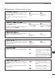
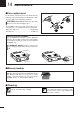
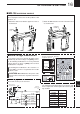
■ MB-106
CARRYING HANDLE
The optional MB-106
CARRYING HANDLE
is convenient
when carrying the transceiver for DX’ peditions, field
operation, etc.
q Attach the rubber feet with the supplied screws as
shown below.
w Attach the MB-106 to the left side of the transceiver
as shown below.
Carrying
handle
Rubber
feet
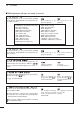
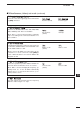
■ Band voltage modification
If you want to connect an external unit which can be
controlled by the band voltage from [ACC] connec-
tor, the following modification is necessary. The band
voltage appears on pin 5 of [ACC] connector after
modification is completed.
Performing this modification is the customer’s re-
sponsibility. Icom does not guarantee this modifi-
cation’s result.
CAUTION: Disconnect the DC power cable
from the transceiver before any work on the trans-
ceiver.
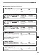
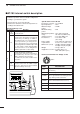
• Band voltage generator circuit
The below circuit is just for reference.
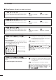
The following band voltage table is for reference only.
Please adjust and confirm against the actual operat-
ing condition.
Bridge these
solder pads
IC-7000’s top view with
top panel is opened
DDS unit
Cooling
fan
Front panel
1.9 MHz
Rotary
switch
Diode
VR 4.7 kΩ
4.7 kΩ
4.7 kΩ
100 µH
100 µH
4700 pF
4700 pF
4700 pF
BAND
8 V
8 V
Extenal
power souce
ACC socket of
an optional unit
GND
10 kΩ
10 kΩ
22 kΩ
VR
Open
VR
VR
OR
3.5 MHz
7 MHz
10 MHz
14 MHz
18/21 MHz
24/28 MHz
1
2
3
4
7
6
5
BAND VOLTAGE
1.9 MHz —
3.5 MHz 6.1 V
7 MHz 5.1 V
10 MHz —
14 MHz 4.1 V
18/21 MHz 3.1 V
24/28 MHz 2.1 V