
User's Manual
72
11
CONTROL COMMAND
D
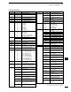
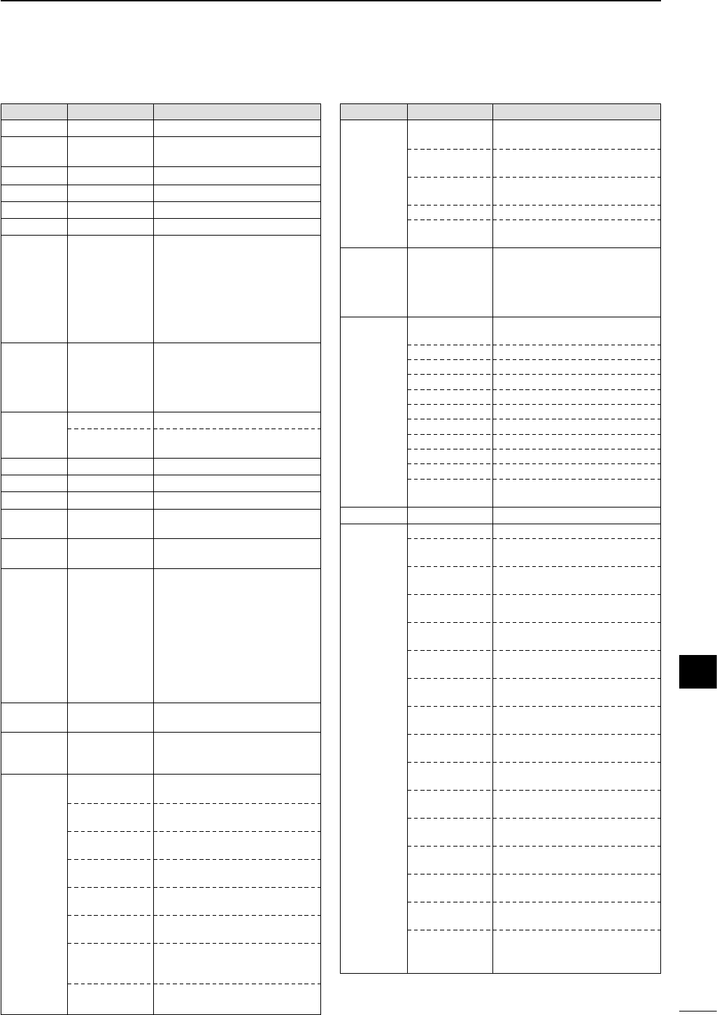
Command table
Command Sub command Description
00 — Send frequency data
01 Same as Send mode data
command 06
02 — Read band edge frequencies
03 — Read operating frequency
04 — Read operating mode
05 — Set operating frequency
06 00 Select LSB
01 Select USB
02 Select AM
03 Select CW
04 Select RTTY
05 Select FM
07 Select CW-R
08 Select RTTY-R
07 — Select VFO mode
00 Select VFO A
01 Select VFO B
A0 Equalize VFO A and VFO B
B0 Exchange VFO A and VFO B
08 — Select memory mode
0001–0105* Select memory channel
*1A=0100, 3b=0105
09 — Memory write
0A — Memory to VFO
0B — Memory clear
0E 00 Scan stop
01 Programmed/memory scan start
0F 00 Turn the split function OFF
01 Turn the split function ON
10 00 Select 10 Hz (1 Hz) tuning step
01 Select 100 Hz tuning step
02 Select 1 kHz tuning step
03 Select 5 kHz tuning step
04 Select 9 kHz tuning step
05 Select 10 kHz tuning step
06 Select 12.5 kHz tuning step
07 Select 20 kHz tuning step
08 Select 25 kHz tuning step
09 Select 100 kHz tuning step
11 — Select/read attenuator (00=OFF,
20=ON (20 dB))
13 00 Announce with voice synthesizer
01 (00=all data; 01=frequency and
02 S-meter level; 02=operating mode)
14 01 + Level data [AF] level setting (0=max. CCW to
255=max. CW)
02 + Level data [RF] level setting (0=max. CCW to
255=11 o’clock)
03 + Level data [SQL] level setting (0=11 o’clock to
255=max. CW)
04 + Level data [IF SHIFT] position setting (0=max.
CCW; 128=center; 255=max. CW)
06 + Level data Noise reduction level setting
(0=min. to 255=max.)
07 + Level data Twin PBT (inside) setting (0=max.
CCW, 128=center, 255=max. CW)
08 + Level data Twin PBT (outside ) setting
(0=max. CCW, 128=center,
255=max. CW)
09 + Level data CW pitch setting (0=300 Hz,
128=600 Hz, 255=900 Hz)
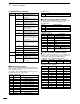
Command Sub command Description
14 0A + Level data RF power setting (0=mini. to
255=max.)
0B + Level data Microphone gain setting (0=mini.
to 255=max.)
0C + Level data Key speed setting (0=slow to
255=fast)
0E + Level data
COMP Level setting (0=0 to 10=10)
0F + Level data Break-IN DELAY setting (20=2.0d
to 130=13.0d)
15 01 Read squelch condition
02 Read S-meter level
11 Read RF power meter
12 Read SWR meter
13 Read ALC meter
16 02 Preamp (0=OFF; 1=preamp 1;
2=preamp 2)
12 AGC selection (1=Fast; 2=Slow)
22 Noise blanker (0=OFF; 1=ON)
40 Noise reduction (0=OFF; 1=ON)
41 Auto notch (0=OFF; 1=ON)
42 Subaudible tone (0=OFF; 1=ON)
43 Tone squelch (0=OFF; 1=ON)
44
Speech compressor (0=OFF; 1=ON)
45 Monitor (0=OFF; 1=ON)
46 VOX function (0=OFF; 1=ON)
47 Break-in (0=OFF; 1=semi break-
in; 2=full break-in)
19 00 Read the transceiver ID
1A 00 Send/read memory contents
01 Send/read band stacking register
contents (see p. 73 for details)
02 Send/read memory keyer con-
tents (see p. 73 for details)
0301 Send/read beep emission set
(0=OFF, 1=ON)
0302 Send/read band edge beep set
(0=OFF, 1=ON)
0303 Send/read beep output level set
(0=min. to 255=max.)
0304 Send/read beep limit set (0=OFF,
1=ON)
0305 Send/read CW carrier point set
(0=LSB, 1=USB)
0306 Send/read CW side tone level set
(0=min. to 255=max.)
0307 Send/read CW side tone limit set
(0=OFF, 1=ON)
0308 Send/read 9600 bps mode set
(0=OFF, 1=ON)
0309 Send/read VOX gain set (0=min.
to 255=max.)
0310 Send/read anti VOX gain set
(0=min. to 255=max.)
0311 Send/read VOX delay time set
(0=0 sec. to 20=2.0 sec.)
0312 Send/read meter selection
(0=Power, 1=SWR, 3=ALC)
0313 Send/read SSB carrier frequency
(00=–200 Hz to 40=200 Hz;
10 Hz steps)
CW: Clockwise, CCW: Counter Clockwise
11