
Operation Manual


1
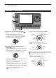
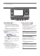
PANEL DESCRIPTION
1-3
e TX/RX LED
Lights green when the squelch opens, or a signal ➥
is received.
Lights red when transmitting. ➥
r MEMORY BANK CONTROL [BANK]
❍ When both the PBT and RIT LEDs are OFF
Rotate to select a Memory bank.
❍ When the PBT LED (y) lights green
(Mode: SSB/CW/RTTY/AM)
Rotate to adjust the receiver’s IF filter passband
width using the DSP circuit.
❍ When the RIT LED (u) lights orange
Disable this control.
t
M-CH CONTROL•CLEAR SWITCH [M-CH]•[CLR]
Push to select the action of the [M-CH/BANK] con-
trols as the Memory/Bank selection, PBT control or
RIT control.
❍ When the both RIT and PBT LEDs are OFF
Rotate to select a Memory channel.
❍ When the RIT LED lights orange
➥ Rotate to adjust the RIT frequency shift.
•The frequency shift rangeis ±9.99 kHz in 10 Hz
steps. The control tunes in 1 Hz steps when the op-
erating frequency readout is set to the 1 Hz step.
➥ Hold down for 1 second to clear the RIT shift
frequency.
✔ What is the RIT function?
The RIT (Receiver Incremental Tuning) shifts the re-
ceive frequency without shifting the transmit frequency.
This is useful for fine tuning stations calling you off-fre-
quency, or when you prefer to listen to slightly different-
sounding voice characteristics.
❍ When the PBT LED lights green
(Mode: SSB/CW/RTTY/AM)
➥ Rotate to adjust the receiver’s IF filter pass-
band width using the DSP circuit.
➥
Hold down for 1 second to reset the PBT set-
tings.
•ThePBTisadjustablein50HzstepsintheSSB/
CW/RTTY modes, and 200 Hz in the AM mode. At
that time, the shift value changes in 25 Hz steps in
the SSB/CW/RTTY modes, and 100 Hz in the AM
mode.
•ThePBTcontrolsfunctionasanIFshiftcontrol.
✔ What is the PBT control?
The PBT function electronically modifies the IF pass-
band width to reject interference. This transceiver uses
the DSP circuit for the PBT function.
y PBT LED
Lights green when the [M-CH/BANK] controls act
as the PBT control.
•Pushthe[M-CH] switch to select PBT control.
u RIT LED
Lights orange when the RIT function is turned ON. ➥
Lights orange when the [M-CH/BANK] ➥ controls
act as the RIT control.
•Pushthe[M-CH] switch to select RIT control.
•The RIT control is the inner control. The outer control
is disabled.
i RIT KEY
RIT
(AI sec. 5)
Push to turn the RIT function ON or OFF. ➥
•Usethe[M-CH] control to vary the RIT frequency.
➥ Hold down for 1 second to add the shift frequency
of the RIT function to, or subtract it from, the dis-
played frequency.
o ANTENNA TUNER/CALL KEY
TUNER/CALL
❍ ANTENNA TUNER KEY Operation (AI sec. 16)
(Frequency band: HF/50 MHz)
➥ Push to turn an optional automatic antenna
tuner ON or OFF (bypass).
➥ Hold down for 1 second to manually tune the
antenna tuner.
•Ifthetunercannottunetheantennawithin20sec-
onds, the tuning circuit is automatically bypassed.
❍ CALL KEY Operation (AI sec. 11)
(Frequency band: 144/430 MHz)
Push to select the Call channel.
In the 70 MHz band, push to sound an error beep.
!0 MENU KEY
MENU
(p. 1-10)
Push to change the set of functions assigned to the
touch keys.
•TogglesthefunctiondisplaymenubetweenM-1,M-2and
M-3 menus or D-1 and D-2 menus.
!1 MIC GAIN/RF POWER ADJUSTMENT KEY
MIC/RF PWR
(p. 3-24)
Push to open the MIC gain/RF power adjustment
display.
•Rotate[M-CH] to adjust the MIC gain.
•Rotate[BANK]
to adjust the RF power.
Frequency band RF output power range
HF/50 MHz 2 to 100 W (AM: 1 to 30 W)
70 MHz* 2 to 50 W (AM: 1 to 15 W)
144 MHz 2 to 50 W
430 MHz 2 to 35 W
•Pushagaintoclosethewindow.
* 70 MHz band transmission is available, depending on the
transceiver version.