IMPORTANT READ THIS [INSTRUCTION. MANUAL CAREFULLY before attempting fo operate the transceiver. SAVE THIS INSTRUCTION MANUAL. This instruction manual ‘contains important safety and operating instructions for the IC-725A. PRECAUTIONS A NEVER apply AC power 1o the [0C 138Y] casket. This could caste a fire or ruin the transceiver.
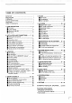
TABLE OF CONTENTS IMPORTANT i PRECAUTIONS EXPLICIT DEFINITIONS e UNPACKING .o TABLE OF.CONT 1 PANEL DESCRIPTION Merton panel . 1 W Function display 3 Microphone (HM-: Gl 4 W Rear panel 0 2 INSTALLATION AND CONNECTIONS . W Mounting the transceiver W Antenna M Connections chart ) M Power supply connections M Lin car amplifier connections i triangulating # Antenna funnest connections 11 M Antenna selector connections .
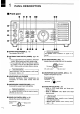
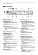
© RF POWER CONTROL {RF PWR] (p. 19) Adjusts the BE output prows from minimum to maximum;: REBEL Decreases ( ’\ Incenses Min. 5w Max 100w *AM mote: Max. 25 W @ DIAL LOCK SWITCH [LOCK] (p. 15} Electronically locks the ‘main dial to prevent eccl: dental: changing: of operating frequency. o memory channel. D MAIN DIAL {pgs. 15,16, 25) = Elects displayed frequency. —After: pushing ‘the: JOUNCE switch:: Selects a memory channel: @ MEMORY WRITE SWITCH MW D= VET)] (pigskin 26,271 ~When pushed and held.
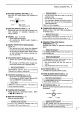
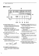
(:Jl 1 PANEL DESCRIPTION M Function display LEFT TUNE N8 [RIT) @Y THRU PREAMBLE Attila ...2 Lsa M=T [Fun cl MEMO VELA L ’ lives U1 L. 4 sure = Y e 000 @ TRANSMIT INDICATOR (p. 18} Shows that the transceivers ran smiting: @ RECEIVE INDICATOR (p. 17} Shows that the squelch is open while receiving. @) LOCK INDICATOR {pi 15} Shows that the main dial is electronically locked: @ S/RF INDICATOR (pgs. 17, 19) =~ Shows the receive signalization while receive: ing.
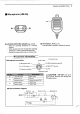
M Microphone (HM-36) O UP/DOWN SWITCHES [UPWIND] (pgs. 25, 29) — Select an operating frequency or & memory channel. = When pushed and held, change the operating Frequency of memory channel continuously. = Cancel the programmed $Can or merry scan: Microphone information Microphone connector PANEL DESCRIPTION 1 @ SWITCH Push and hold to transmit. Release to receive. Front panel view (@ AF output G Microphone input (% GND {microphone ground).
ol 1 PANEL DESCRIPTION M Rear panel l‘fi\i 00 B GROUND TERMINAL [GND] (p. 7} Constricts iota ground to prevent electrical shocks, TV {Television Interference. BCL (Broadcasting Noninterference problematical. @ SEND CONTROL JACK [SEND] (. 10) Grounded ‘while transmitting. ' When grounded transmits; Used o control external equipment such as anon-com linear amplifier: & ALC INPUT JACK [ALC] (pgs: 6,10 12) Connects: fo the ALC output jack of a noncom linger amplifier.
2 INSTALLATION AND CONNECTIONS Il Mounting the transceiver For base operation Electrification which: =~ allows adequate air circulation. — g free from extreme heat, cold, or vibrations. — s away from TV chefs. radios and other electromagnetic sources, Far mobile operation Mount the transceiver ‘using: an optional ‘IAMBICS MOBILE: MOUNTING BRACKET . Select a location which: —can support the weight of the transceiver. — does not interfere with the operation of the vehicle.
3 OPERATION M Initial settings Before performing the initial settings. make sure il required connections are complete. Be tore power ON. set controls and switches as showiness the figure below; [POWER] switch: = I o OFF LIMIT) control. Center GAIN] control. %% ( Q\\\ o AF PWR] control. cow Iy w cw [SQL] control: COWL LA ; CW 2 Max, clockwise COW: Max. counterclockwise M Basic operation 1) Tur the [POWER) switch o the ON position. rowan (gF ) witch 551 O Hen SMOTE "SPLIT.
OPERATION 3 M What are VFO and MEMORY modes? MEMORY. mode 30 memory channels store your often-Used frequent: ices and operating modes. VFO mote The 1C-725A has two Vets: VFO A and VFO B, Each VEQ has a frequency and operating mode. VF mode HIE A" appears: MEMORY mode MEME: &FWT& Wen O | i 1 e 24 The differences between VFO mode and MEMORY mode VFQ mode VEO A and VEO B have independent frequencies gnd operating modes.
3 OPERATION M Frequency setting For ham band use 13 Push the {T9) switch several: mes: unlit the 2. tuning step Indicators ¥ ww " appear above the 10 MHz and 1 MHz digits. Select Wow above the 10 MHz and 1 MH2 ifs: . 2} Rotas the main dial to select the desired band. Operating mode changes according to the soloed band: 3): Pushiness (TS switch 1 dime. wrw T disappears. Rotate the main editorial: select the desired frequency: * Phish e [TS] switch 1 dime 10 Select the 1 kHz toning step.
OPERATION 3 1 kHz tuning step The ‘operating frequency can bie changed: in: 1 kHz steps for quick tuning: 19 Push the [TS] switch ‘several ‘mes: unfit *w! appear son the: 1 kHz digit: Hie 1 kHz fining tep is:selected: ZHB A0 ‘ 2} Rotate the man dial change the frequency. 3) Push: the [18] switch 3 times until *w-" disappears. 4} Rotate: the main dial for fine tuning if required; N 7 NOTE: Whitman AM or FM mode Is selected; the 1 % KHz tuning step s automatically selected.
3 OPERATION I Voice transmitting [TUNER] switch Push ‘whets an optional AT=180: or AH-3: HE AUTOMATIC ANTENNAE: ER:is connected, e {RF PWR] control Adjusts: the RE. output power. Basic voice transmitting % CAUTION: Transmitting without an antenna é may damage the transceiver: After completing the receiving: procedures ‘on pgs. 17 and: 18, perform {ran smiting.
I CW mode operation OPERATION 3 Connects CW key o the KEY] jack on the rear panel. @ «© KEY] @ . @ec Basic CW operation 22 NOTE: Only semi break-in operation is possible. Full break-in operational ‘and manual transmitter: ,% cave switching are not possible. 1) Turn the [POWER]switch 1o the: ON: position: 2y Rush the MODE] perseverance dimes until "CW? appears: * To use “CONY an optional FLA or FLA W NARROW FILTER Is required.
3 OPERATION M RATTY mode operation Connect & TNC with RATTY: capability:to the [ACCRA) socket on the rear panel. Personal computer T Here i & HS-232C port THC Wt RATTY @ ui 7 [[[ease) capability Abbots s« 89 0@ AGENCY] G oo AE input and output revels Your: TNC {Terminal ‘Node: Controller: should be ‘connected: to:the BACCHIC] socket.: ‘Refer to pi 12 and your TNG instruction manual for connection. When: connected fo the Interconnection.
M Frequency equalizing operation OPERATION 3 Undismayed: VRO frequency . and ‘operating: mode are equalizer displayed VF. 13 Elect FOAM or VFO B, 2} Push and hold the [FUN] switch; then push the switch unit the speaker smile 3 beep phones.
3 OPERATION I AH-3 HF AUTOMATIC ANTENNA TUNER An: optional AH-3 allows: you 'HF operation: where antenna element length s restricted due o space’ 7 £, WANING: DANGER HIGH / VOLTAGE! NEVER ouch the ‘antenna terminal: ground terminal o antenna element while transmitting. Place the AH:3 and antenna 7 in positions where o one douches them. S NEVER operate the ‘an antenna element.
OPERATION 3 I AT-160 HF AUTOMATIC ANTENNA TUNER The AT:160 marches the 1C-725A to' the “anteing automatically: The AT-160 has memories for auto preset. No preset operation is required; Installation and connection Refer:to p.: 11and the AT160 instruction. manual; connect the AT-160: o the IC-725A: Al required cables are supplied with the AT160 SET mode smelting Refer fo pgs. 30, 31, select tuner type "AT 1607 Only: when the antenna s not marched o the operating frequency and SWH s high. activate the AT-160.
= 4 MEMORY CHANNELS | M Channel functions The IX-725A's 32 memory channels ‘are for programmed:scan and storing often-used frequencies. 105 Normal memory: channels. A xref All memory channels returnable. The frequency and piquancy and mode'in sate channel. operating: mode:in: machinery channel can: be Spit memory | channels for | shpt changed temporarily. I requited, the changed frequency: operation.
I Memory channel programming Memory: channel ‘programming: can: be performed either in VEO mode or MEMORY. mode. MEMORY CHANNELS 4 While in VFQ mode 1¥ 0 VEQ: mode; select the desired frequency. and operating mode: 2y Push the [FUN] switch. then rotate the main dial 1o select @ memory channel number; *To confirm the memory channel contents, rear 1o gaps at left.
M Split memory channels Memory: channels: 26 30 are: split: memory Chan: angles. @ Frequencies: and:operating |modes gan be programmed for both transmitting and receiving. MEMORY CHANNELS 4 ‘These memory channels: ‘are: especially useful for repeater operation: Split memory channel selection Hefner fop. 25, select one of memory. channels 26. = 30.
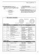
6 SET MODE M Electable modes I required; delectable mode can be restricted. MOVE: o O ! ~Initial settling before shipping:all modes ON Select ON or OFF for each mode; ~ ON:The mode is delectable. ~ OFF: The mode is not electable, You can inhibit not used modes: This is convenient for example: = When an optional UL-9 FM UNIT is not installed, tum £M mode and FM tone mode OFF. —When an optional FL-52A or FL-53A CW NAR: ROW FILTER is not installed. ‘turn CW. Gamow mode OFF.
M Cl-V address SET MODE 6 The IC725A has' com standard address ‘SEH for CFV System: i required select a different address. Main dial = {atrial setting before shipping: 3EH = Electable address ranger = TFH Up o 4 CIV transceivers can be connected to an optional CT:17 EVE LEVEL CONVERTER, 'To dis tin: gush equipment, each CI-V transceiver has its own addressing hexadecimal code; “When al IC:725A s connected, select Com standard address 3EH.
7 MAINTENANCE AND ADJUSTMENT M Disassembly For internal maintenance ‘and: optional installation, disassemble: the transceiver according 1o the follow: ing procedures. CAUTION: DISCONNECT the DC power cable from ‘the ‘transceiver before performing any internal work. Removing top and bottom covers Unscrew: 12 screws {Fig:1} Flg Removing PA unit cover: Unscrew 11 screws. (Fig. 2) Y Removing the front panel Unscrew 4 screws: (Fig.3) Resew fot Tk e MM anti Removing the MAIN unit Disconnect.
Bl 8 OPTIONS INSTALLATION UNIT The 1I1-9 provides FM: mode capabilities for the 1C-725A. The UL-9 also allows you 1o access a repeater. Refer o p. 22 for repeater operation. To access ‘a repeater that requires 2 sub audible tone; defer 1o the box below: 7, NOTE: Connectors on the UL9 must be con%, nested to corresponding pins on the MAIN unit. 1) Realer to p. 33! remove the bottom cover. 2} Attach the U9 on' the MAIN unit: 3): Replace ihe bottom cover.
OPTIONS INSTALLATION 8 M CR-338 HIGH-STABILITY CRYSTAL UNIT The CR-338 improves the total frequency stability « Frequency stability: 1 R0S ppm (=10 C e 380G FIEF O+ TAT ) 1) Celerity p. 33 remove: the top cover and the Plenitude 2y Unsold er. and: remove the original crystal: from the PLL Unit. » Sea DE-soidering braid. 3) Unsold er The 4 positions on the PLL unit where the CR-338 fs installed. 43 Install the CR-338 In the PLL unit. bottom of the .CR-338: MUST.