
Operation Manual


19
CONTROL COMMAND
19-2
Remote control (CI-V) information
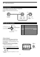
D CI-V connection
The transceiver's operating frequency, mode, VFO
and memory selection, can be remotely controlled
using a PC.
Choose your connection method from the following:
• A USB cable (A-B type, user supplied)
The required USB driver and driver installation guide
can be downloaded from the Icom web site.
Go to “http://www.icom.co.jp/world,” and then click
“Support,” “Firmware Updates / Software downloads”
in sequence.
L The download procedure on the web page may be
changed without notice.
• The optional CT-17 CI-V level converter.
Connects to a PC with an RS-232C port.
D Preparing
The Icom Communications Interface V (CI-V) is used
for remote control.
To control the transceiver, rst set its address, data
communication speed, and transceive function. These
settings are set in Set mode.
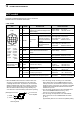
D Data format
The CI-V system can be written using the following
data formats. Data formats differ according to
command numbers. A data area or sub command is
added for some commands.
ct-17
IC-7300
• Connection example (using CT-17)
PC
9~15 V DC
mini-plug cable
Controller to IC-7300
IC-7300 to controller
FE FE 94 E0 Cn Sc Data area FD
Preamble
code (fixed)
Transceiver’s
default address
Controller’s
default address
Command number
(see the command table)
Sub command number
(see command table)
BCD code data for
frequency or memory
number entry
End of message
code (fixed)
FE FE E0 94 FB FD
FE FE E0 94 FA FD
Preamble
code (fixed)
Controller’s
default address
Transceiver’s
default address
OK code
(fixed)
End of message
code (fixed)
NG code
(fixed)
q w e r t y u
FE FE E0 94 Cn Sc Data area FD
q w e r t y u
OK message to controller
NG message to controller