
User Guide

2
1
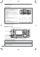
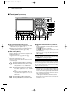
PANEL DESCRIPTION
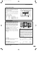
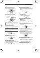
•When functioning as RF gain control
(Squelch is fixed open; SSB, CW, RTTY only)
•When functioning as squelch control
(RF gain is fixed at maximum.)
While rotating the RF gain control, noise may be
heard. This comes from the DSP unit and does not
indicate an equipment malfunction.
u MIC GAIN CONTROL [MIC GAIN]
Adjusts microphone input gain.
•The transmit audio tone in SSB, AM and FM modes can
be adjusted in tone control set mode. (p. 88)
✔
How to set the microphone gain.
Set the [MIC] control so that the ALC meter sometimes
swings during normal voice transmission in SSB mode.
Make sure that voice peak readings do not exceed the ALC
range brackets on the meter.
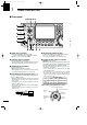
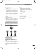
i AF CONTROL [AF] (inner control)
Varies the audio output level from the speaker.
o RF POWER CONTROL [RF PWR]
Continuously varies the RF output power from min-
imum (less than 5 W*) to maximum (100 W*).
* AM mode: less than 5 W to 40 W
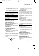
!0 CW PITCH CONTROL [CW PITCH] (p. 28)
Shifts the received CW audio pitch and monitored
CW audio pitch without changing the operating fre-
quency.
•The pitch can be changed from 300 to 900 Hz in approx.
25 Hz steps.
!1 ELECTRONIC CW KEYER SPEED CONTROL
[KEY SPEED] (p. 28)
Adjusts the internal electronic CW keyer’s speed.
• 6 wpm (min.) to 60 wpm (max.) can be set.
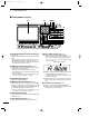
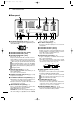
!2 AUTO NOTCH/MANUAL NOTCH SWITCH
[A/NOTCH] (p. 52)
Toggles the notch function between manual and au-
tomatic when pushed.
•“NOTCH” appears when manual; “A NOTCH” appears
when automatic notch is selected.
!3 NOTCH CONTROL [NOTCH] (outer control; p. 52)
Adjusts the notch filter frequency to remove an in-
terfering signal.
!4 ANTENNA SELECTOR SWITCH [ANT] (p. 74)
Switches the antenna connector selection between
ANT1 and ANT2 when pushed.
!5 NOISE REDUCTION LEVEL CONTROL [NR]
(inner control; p. 52)
Adjusts the noise reduction level when the noise re-
duction is in use. Set for maximum readability.
!6
ANTENNA TUNER SWITCH [TUNER] (pgs. 75, 76)
➥ Turns the antenna tuner ON and OFF (bypass)
when pushed momentarily.
➥ Starts to tune the antenna manually when
pushed for 1 sec.
•When the tuner cannot tune the antenna, the tuning
circuit is bypassed automatically after 20 sec.
!7 NOISE REDUCTION SWITCH [NR] (p. 52)
Switches the noise reduction ON and OFF.
•“NR” appears while the noise reduction is activated.
NR NOTCH
OFF
Decreases
Increases
NR NOTCH
Low frequency High frequency
Slow Fast
KEY SPEED
CW PITCH
IncreasesDecreases
RF PWR
IncreasesDecreases
AF RF/SQL
No audio output
Max. audio output
Decreases Increases
MIC GAIN
Recommended level for
an Icom microphone
IncreasesDecreases
Squelch is
open.
S-meter
squelch
S-meter squelch
threshold
Noise squelch
threshold
(FM mode)
Shallow Deep
Noise squelch (FM mode)
Minimum RF gain
Adjustable
range
Maximum
RF gain
IC-7400.qxd 02.4.2 11:35 Page 2