IC-F111_121_211_221S-2.qxd 05.9.
IC-F111_121_211_221S-2.qxd 05.9.16 10:37 AM Page i (1,1) IMPORTANT PRECAUTION READ ALL INSTRUCTIONS carefully and com- RWARNING! NEVER connect the transceiver to an AC outlet. This may pose a fire hazard or result in an electric shock. pletely before using the transceiver. SAVE THIS INSTRUCTION MANUAL — This instruction manual contains important operating instructions for the IC-F111S/F121S VHF TRANSCEIVER and ICF211S/F221S UHF TRANSCEIVER.
IC-F111_121_211_221S-2.qxd 05.9.16 10:37 AM Page ii (1,1) TABLE OF CONTENTS USE the supplied microphone only. Other microphones have different pin assignments and may damage the transceiver. DO NOT use or place the transceiver in areas with temperatures below –22°F (–30°C) or above +140°F (+60°C), or in areas subject to direct sunlight, such as the dashboard of a vehicle. AVOID operating the transceiver without running the vehicle’s engine.
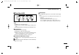
IC-F111_121_211_221S-2.qxd 1 05.9.16 10:37 AM Page 1 (1,1) PANEL DESCRIPTION ■ Front panel Function LED (p. 2) q 1 2 3 4 TX/RX w e q AF VOLUME CONTROL KNOB ➥Rotate the knob to adjust the audio output level. • Minimum audio level is pre-programmed. w MICROPHONE CONNECTOR ➥Connect the supplied microphone or optional DTMF microphone. NEVER connect non-specified microphones. The pin assignments may be different and the transceiver may 1 r be damaged.
IC-F111_121_211_221S-2.qxd 05.9.16 10:37 AM Page 2 (1,1) PANEL DESCRIPTION ■ Function LED D MICROPHONE ➥The supplied microphone has a PTT switch and a hanger hook. q 1 2 3 4 TX/RX e 1 w q CHANNEL INDICATORS ➥ Indicates the operating channel. ➥ Blinks when receiving a signal during scanning operation. ➥ All LEDs blink while entering the power ON password. • The following functions are available when the microphone is on or off hook: - Automatic scan start when hook on.
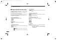
IC-F111_121_211_221S-2.qxd 1 05.9.16 10:37 AM Page 3 (1,1) PANEL DESCRIPTION ■ Programmable function keys The following functions can be assigned to [P0], [P1], [P2] and [P3] programmable function keys. Consult your Icom Dealer or System operator for details concerning your transceiver’s programming. In the following explanations, programmable function names are bracketed. The specific switch used to activate the function depends on programming. ¡ CH UP AND DOWN KEYS Select an operating channel.
IC-F111_121_211_221S-2.qxd 05.9.16 10:37 AM Page 4 (1,1) PANEL DESCRIPTION ¡ MONITOR KEY Activates one of (or two of) the following functions MONI on each channel independently: • Push and hold the key to unmute the channel (audio is emitted; ‘Audible’ condition). • Push the key to toggle the mute and unmute conditions (toggles ‘Audible’ and ‘Inaudible’). • Push the key to mute the channel (sets to ‘Inaudible’ only). • Push the key to unmute the channel (sets to ‘Audible’ only).
IC-F111_121_211_221S-2.qxd 1 05.9.16 10:37 AM Page 5 (1,1) PANEL DESCRIPTION ¡ EMERGENCY KEY Push and hold the key to transmit an emergency call. EMER • If you want to cancel the emergency call, push and hold (or push) the key again before transmitting the call. • Depending on the pre-setting, the emergency call is transmitted one time only, or repeatedly, until receiving a control code. ¡ SCRAMBLER KEY • Push and hold to turn the voice scrambler funcSCRM tion ON.
IC-F111_121_211_221S-2.qxd 05.9.16 10:37 AM Page 6 (1,1) OPERATION 2 ■ Turning power ON ■ Channel selection q Push [ Several types of channel selection are available. The methods may differ according to your system setup. ] to turn the power ON. w If the transceiver is programmed for a start up passcode, input the digit codes as directed by your Dealer. • The keys in the table below can be used for password input: • The transceiver detects numbers in the same block as identical.
IC-F111_121_211_221S-2.qxd 2 05.9.16 10:37 AM Page 7 (1,1) OPERATION ■ Receiving and transmitting RECEIVING: q Push [POWER] to turn the power ON. w Push [CH UP] or [CH DN] to select a channel. e When receiving a call, adjust the audio output level to a comfortable listening level. TRANSMITTING: r Take the microphone off hook. • The channel is busy when TX/RX indicator turns green. - According to the trasceiver’s setting; • 2-tone, 5-tone mute may be released.
IC-F111_121_211_221S-2.qxd 05.9.16 10:37 AM Page 8 (1,1) OPERATION D Scrambler function The UT-109 (#02) or UT-110 (#02) optional voice scrambler unit provides high performance private communication between stations with the same scrambler codes. q Push and hold [SCRM] to turn the scrambler function ON. w Push [SCRM] to turn the function OFF. 2 eThen push [P2] and [P3] to set the desired level/condition. rPush [POWER] (or push and hold [P0]) again to exit set mode.
IC-F111_121_211_221S-2.qxd 3 05.9.16 10:37 AM Page 9 (1,1) CONNECTION AND MAINTENANCE ■ Rear panel and connection w Optional speaker (SP-22) q Antenna R C A U T I O N ! N E V E R r emove the fuse-holder from the DC power cable. red: black: 12V Battery To the antenna connector NEVER connect to a 24 V battery. t NOTE: Use the terminals as shown below for the cable connections.
IC-F111_121_211_221S-2.qxd 05.9.16 10:37 AM Page 10 (1,1) CONNECTION AND MAINTENANCE q ANTENNA CONNECTOR Connects to an antenna. Ask your Dealer about antenna selection and placement. ■ Supplied Accessories q w e r w MICROPHONE HANGER Connect the supplied microphone hanger to the vehicle’s ground for microphone on/off hook functions. (See p. 1) y u i o !0 t EXTERNAL SPEAKER JACK Connect a 4–8 Ω external speaker, if desired. t KEY-STICKER e DC POWER RECEPTACLE Connects to a 12 V DC battery.
IC-F111_121_211_221S-2.qxd 3 05.9.16 10:37 AM Page 11 (1,1) CONNECTION AND MAINTENANCE ■ Mounting the transceiver ■ Optional UT-108 installation The universal mounting bracket supplied with your transceiver allows overhead mounting. • Mount the transceiver securely with the 4 supplied screws to a thick surface which can support more than 1.5 kg. Install the optional UT-108 DTMF decoder unit as follows: q w e r Turn the power OFF, then disconnect the DC power cable.
IC-F111_121_211_221S-2.qxd 05.9.16 10:37 AM Page 12 (1,1) CONNECTION AND MAINTENANCE ■ Optional UT-109 /UT-110 installation 3 ■ Optional OPC-617 installation Install the OPC-617 as shown below. q Turn the power OFF, then disconnect the DC power cable. w Unscrew the 4 screws, then remove the bottom cover. e Cut the pattern on the PCB at the TX mic circuit (MIC) and RX AF circuit (DISC) as shown below. r Install the scrambler unit as described in optional UT-108 installation in the page at left.
IC-F111_121_211_221S-2.qxd 3 05.9.16 10:37 AM Page 13 (1,1) CONNECTION AND MAINTENANCE ■ Antenna A key element in the performance of any communication system is an antenna. Ask your Dealer about antennas and the best places to mount them. ■ Fuse replacement A fuse is installed in the supplied DC power cable. If a fuse blows or the transceiver stops functioning, track down the source of the problem, if possible, and replace the damaged fuse with a new rated one.
IC-F110_210S_EUR-2.qxd 05.9.26 9:33 AM Page 14 (1,1) OPTIONS 4 SP-22 EXTERNAL SPEAKER Compact and easy-to-install. Input impedance : 4 Ω Max. input power : 5 W HM-152/HM-152T/HM-148 • HM-152 : Hand microphone. The same as that supplied with the transceiver. • HM-152T : DTMF microphone. • HM-148 : Heavy duty microphone. SM-25 Desktop microphone. UT-108 DTMF DECODER UNIT Provides pager and code squelch capabilities. UT-109/UT-110 (#02) VOICE SCRAMBLER UNIT • UT-109 : Non-rolling type (max.
IC-F111_121_211_221S-2.qxd 5 05.9.16 10:37 AM Page 15 (1,1) SAFETY TRAINING INFORMATION Your Icom radio generates RF electromagnetic energy during transmit mode. This radio is designed for and classified as “Occupational Use Only”, meaning it must be used only during the course of employment by individuals aware W ARN ING of the hazards, and the ways to minimize such hazards. This radio is NOT intended for use by the “General Population” in an uncontrolled environment.
IC-F111_121_211_221S-2.qxd 05.9.
IC-F111_121_211_221S-2.qxd 05.9.16 10:37 AM A-6199H-1EX-w Printed in Japan © 2002–2005 Icom Inc.