IC-F1610_F2610.qxd 03.3.
IC-F1610_F2610.qxd 03.3.7 16:29 Page ii (1,1) IMPORTANT READ ALL INSTRUCTIONS CAUTIONS carefully and com- pletely before using the transceiver. SAVE THIS INSTRUCTION MANUAL—This instruction manual contains important operating instructions for the IC-F1610 VHF TRANSCEIVER or IC-F2610 UHF TRANSCEIVER. EXPLICIT DEFINITIONS RWARNING! NEVER connect the transceiver to an AC outlet. This may pose a fire hazard or result in an electric shock.
IC-F1610_F2610.qxd 03.3.7 16:29 Page iii (1,1) DO NOT connect the transceiver to a power source using reverse polarity. This connection will not only blow fuses but also may damage the transceiver. DO NOT use or place the transceiver in areas with temperatures below –20°C or above +55°C or, in areas subject to direct sunlight, such as the dashboard. AVOID operating the transceiver without running the vehicle’s engine.
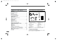
IC-F1610_F2610.qxd 03.3.7 16:29 Page iv (1,1) TABLE OF CONTENTS IMPORTANT . . . . . . . . . . . . . . . . . . . . . . . . . . . . . . . . . . . . ii EXPLICIT DEFINITIONS . . . . . . . . . . . . . . . . . . . . . . . . . . . ii CAUTIONS . . . . . . . . . . . . . . . . . . . . . . . . . . . . . . . . . . . . . ii TABLE OF CONTENTS . . . . . . . . . . . . . . . . . . . . . . . . . . . iv SUPPLIED ACCESSORIES . . . . . . . . . . . . . . . . . . . . . . . .
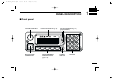
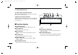
IC-F1610_F2610.qxd 03.3.7 16:29 Page 1 (1,1) PANEL DESCRIPTION 1 ■ Front panel VOLUME CONTROL FUNCTION DISPLAY (p. 6) CH UP/DOWN KEYS (p. 2) (programmable) LOW P0 MICROPHONE CONNECTOR P1 P2 P3 PROGRAMMABLE FUNCTION KEYS (pgs.
IC-F1610_F2610.qxd 03.3.7 16:29 1 Page 2 (1,1) PANEL DESCRIPTION VOLUME CONTROL Adjusts the audio output • Minimum audio level (when setting control maximum counter clockwise) is pre-programmed. CHANNEL UP/DOWN KEYS [ ]/[ ]([CH UP]/[CH DN]) Push to select an operating channel. • Can be programmed for one of several functions by your dealer. POWER SWITCH Turns the power on and off.
IC-F1610_F2610.qxd 03.3.7 16:29 Page 3 (1,1) PANEL DESCRIPTION BANK KEY BANK Selects a memory bank. 1 • Push the key to unmute the channel (sets to ‘audible’ only). • Push the key after communication is finished to send a ‘reset code.’ ☞ NOTE: The unmute condition (‘audible’ conditions) may PRIORITY CHANNEL KEYS PRI A Select priority A or priority B channel. PRI B SCAN KEYS SCN A Start/stop scan A or scan B. SCN B SCAN TAG KEY Adds or deletes the selected channel to the scan TAG group.
IC-F1610_F2610.qxd 03.3.7 16:29 1 Page 4 (1,1) PANEL DESCRIPTION the following: [CALL] (incl. CAL A and CAL B), [MONI] and [EMER] keys. OUTPUT POWER SELECTION KEYS LOW1 Select the transmit output power temporarily or permanently, depending on the pre-setting. LOW2 • Ask your dealer or system operator for the output power level for each selection. BEEP KEY Push to toggle beep tones on and off. BEEP • These are the confirmation beep tones that by default are emitted each time a key is pushed.
IC-F1610_F2610.qxd 03.3.7 16:29 Page 5 (1,1) PANEL DESCRIPTION 1 EMERGENCY KEY EMER Push and hold the key to transmit an emergency call. D Programmable functions without supplied stickers • If you want to cancel the emergency call, push (or push and hold) the key again before transmitting the call. • The emergency call is transmitted one time only or repeatedly until receiving a control code, depending on the pre-settting. TX CODE CHANNEL UP/DOWN KEY Push to select a TX code channel directly.
IC-F1610_F2610.qxd 03.3.7 16:29 1 Page 6 (1,1) PANEL DESCRIPTION TX CODE CHANNEL UP/DOWN FUNCTION When a key is assigned this function, push it to increment or decrement the TX code channel. TURBO SpeeDial A/B/C/D FUNCTIONS During SmarTrunk II™ operation, when a key is assigned this function, push it to automatically dial a commonly used number with one push. ■ Function display q TRANSMIT INDICATOR Appears while transmitting or sending a 5-tone code. w BUSY INDICATOR Appears while the channel is busy.
IC-F1610_F2610.qxd 03.3.7 16:29 Page 7 (1,1) OPERATION 2 ■ Turning power on ■ Channel selection ➀ Push [ The method for selecting channels may differ according to your system. ] to turn power on. • A power-up alert tone sounds for about 1 sec. and an opening message may appear. ➁ If the transceiver is programmed with a startup password, input the code from the keypad as instructed by your system operator.
IC-F1610_F2610.qxd 03.3.7 16:29 2 Page 8 (1,1) OPERATION ■ Receiving and transmitting RECEIVING: ➀ Push [ ] to turn power ON. ➁ Push [CH UP]/[CH DN] to select a channel. ➂ When receiving a call, adjust the volume to comfortable listening level. TRANSMITTING: ➃ Lift the microphone off the microphone hanger. • 5-tone mute may be released (the ‘audible’ condition is selected and “[ ]” appears. • A priority channel may be selected automatically. ➄ Wait for the channel to become clear.
IC-F1610_F2610.qxd 03.3.7 16:29 Page 9 (1,1) OPERATION 2 D Tx code channel selection D Tx code number selection If the transceiver has the [TX CH] key, display can be toggled with the operating channel number (or name) and Tx code channel number (or name). When the Tx code channel number (or name) is displayed, the [ ]/[ ] key selects the Tx code channel. If the transceiver has the [CODE] key, Tx code contents can be changed within the allowable digits.
IC-F1610_F2610.qxd 03.3.
IC-F1610_F2610.qxd 03.3.7 16:29 Page 11 (1,1) CONNECTION AND INSTALLATION 3 q ANTENNA CONNECTOR Connects to an antenna. Ask your dealer about antenna selection and optimal antenna locations. w MICROPHONE HANGER Connects the supplied microphone hanger to the vehicle’s ground for the hanger function. e DC POWER RECEPTACLE Connects to a 12 V DC battery. Pay attention to polarities. NEVER connect to a 24 V battery. This could damage the transceiver.
IC-F1610_F2610.qxd 03.3.7 16:29 3 Page 12 (1,1) CONNECTION AND INSTALLATION ■ Mounting Separation (using RMK-1) Flat washer Attachment (for front panel) Rear plate Spring washer OPC-609 Fig. 1 Fig. 2 Attachment (for main unit ) When using self-tapping screws ■ Separation Supplied screws with the RMK-1 ➀ Separate the front panel from the transceiver main unit using the allen wrench (1⁄32″). ➁ Connect the optional OPC-609 cable to both the front and main unit attachments (figures 1 and 2).
IC-F1610_F2610.qxd 03.3.7 16:29 Page 13 (1,1) CONNECTION AND INSTALLATION 3 ■ Optional UT-105 installation The Optional UT-105 provides SmarTrunk II™ functions. Install the unit as follows: ➀ Turn power off, then disconnect the DC power cable. ➁ Unscrew the 4 screws, then remove the bottom cover. ➂ Install the unit as shown in the diagram below. ➃ Replace the bottom cover and screws, then the DC power cable.
IC-F1610_F2610.qxd 03.3.7 16:29 4 Page 14 (1,1) OPTIONAL SmarTrunk II™ OPERATION ■ SmarTrunk II™ and conventional modes This transceiver has SmarTrunk II™ compatible capabilities. The optional UT-105 allows communication in conventional channels or SmarTrunk II™ channels. Select a channel bank for SmarTrunk II™ before trunking operation. Push [BK UP] or [BK DN] one or more times to select a channel bank for conventional channels or SmarTrunk II™ channels.
IC-F1610_F2610.qxd 03.3.7 16:29 Page 15 (1,1) OPTIONAL SmarTrunk II™ OPERATION 4 D Terminating a call D Programming memory speed dial After completing a call, push [#] to disconnect (hang up). ➀ Push and hold [M] until you hear a high-pitched beep. ➁ Enter the memory location (0–9, A, B, C, D), the telephone IMPORTANT: If one person in the conversation terminates a call, all participants will be cut off. D Last number redial Push [M], [M] to automatically redial the last number called.
IC-F1610_F2610.qxd 03.3.7 16:29 4 Page 16 (1,1) OPTIONAL SmarTrunk II™ OPERATION D Clear channel alerting If all channels are busy the transceiver automatically begins searching for an open channel and beeps every ten seconds. When two short beeps (low-pitched, then high-pitched) are heard, a channel is available. Push [M], [M] immediately to redial the last number. ☞ NOTE: For additional operating instructions, contact your dealer for details.
IC-F1610_F2610.qxd 03.3.7 16:29 Page 17 (1,1) OPTIONS EX-1761 MEMORY EXPANSION UNIT Expands the number of available memory channels to 256 for large system operation. HM-100T DTMF MICROPHONE OPC-617 ACC CABLE Provides external terminal connection. OPC-822 INTERFACE CABLE 5 SP-22 EXTERNAL SPEAKER Supplied with some versions. Input impedance: 4 Ω Max. input power: 5 W UT-96 5-TONE UNIT Provides 5-tone decoder capabilities (supplied with some versions).
IC-F1610_F2610.qxd 03.3.7 16:29 Page 18 (1,1) Count on us! A-5547H-1EX-q Printed in Japan © 1998 Icom Inc.