!IC-F25SR-0.qxd 06.10.
!IC-F25SR-0.qxd 06.10.5 6:31 PM Page i (1,1) IMPORTANT READ ALL INSTRUCTIONS carefully and completely before using the transceiver. SAVE THIS INSTRUCTION MANUAL— This instruction manual contains important operating instructions for the ICF25SR PMR446 FM TRANSCEIVER. EXPLICIT DEFINITIONS WORD DEFINITION RWARNING Personal injury, fire hazard or electric shock may occur. CAUTION NOTE Equipment damage may occur. If disregarded, inconvenience only. No risk of personal injury, fire or electric shock.
!IC-F25SR-0.qxd 06.10.5 6:31 PM Page ii (1,1) PRECAUTIONS R CAUTION! NEVER hold the transceiver so that the antenna is very close to, or touching exposed parts of the body, especially the face or eyes, while transmitting. The transceiver will perform best if the microphone is 5 to 10 cm away from the lips and the transceiver is vertical. R CAUTION! NEVER operate the transceiver with a headset or other audio accessories at high volume levels. R CAUTION! NEVER short the terminals of the battery pack.
!IC-F25SR-0.qxd 06.10.5 6:31 PM Page iii (1,1) DOC CE versions of the IC-F25SR which display the “CE” symbol on the serial number seal, comply with the essential requirements of the European Radio and Telecommunication Terminal Directive 1999/5/EC. DECLARATION OF CONFORMITY We Icom Inc.
!IC-F25SR-0.qxd 06.10.
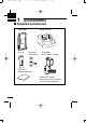
!IC-F25SR-0.qxd 1 06.10.5 6:31 PM Page 1 (1,1) ACCESSORIES ■ Supplied accessories Battery pack Belt clip Battery charger Jack cover (with screws) AC adapter*1 (for the battery charger) Unit cover*2 (double-sided tape) *1 Depends on version. *2 Use the unit cover as a spare. Ask your dealer for details.
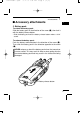
!IC-F25SR-0.qxd 06.10.5 6:31 PM Page 2 (1,1) ACCESSORIES 1 ■ Accessory attachments 1 ï Battery pack To attach the battery pack: Slide the battery pack in the direction of the arrow (q), then lock it with the battery release button. • Slide the battery pack until the battery release button makes a ‘click’ sound. To release the battery pack: Push the battery release button in the direction of the arrow (w). Then slide the battery pack in the direction opposite to the arrow (q).
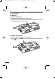
!IC-F25SR-0.qxd 1 06.10.5 6:31 PM Page 3 (1,1) ACCESSORIES D Belt clip To attach the belt clip: q Release the battery pack if it is attached. w Slide the belt clip in the direction of the arrow until the belt clip is locked and makes a ‘click’ sound. To detach the belt clip: q Release the battery pack if it is attached. w Pinch to lift the clip (q), and slide the belt clip in the direction of arrow (w).
!IC-F25SR-0.qxd 06.10.5 6:31 PM Page 4 (1,1) ACCESSORIES 1 ï Jack cover Attach the jack cover when the optional speaker-microphone or headset is not used. To attach the jack cover: q Attach the jack cover to the [MIC/SP] jack. w Tighten the screws using a Phillips screwdriver. To detach the jack cover: q Unscrew the screws using a Phillips screwdriver. w Detach the jack cover for the optional speaker-microphone or headset connection.
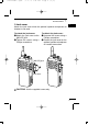
!IC-F25SR-0.qxd 2 06.10.5 6:31 PM Page 5 (1,1) PANEL DESCRIPTION ■ Front, top and side panels q Antenna u w e Speaker y r t Microphone q CHANNEL SELECTOR [CH selector] Rotate to select the pre-programmed memory channels. w VOLUME CONTROL [VOL] Rotate to turn the power ON/OFF and adjust the audio level.
!IC-F25SR-0.qxd 06.10.5 6:31 PM Page 6 (1,1) PANEL DESCRIPTION 2 e LED INDICATOR (p. 7) ➥ Lights red while transmitting. ➥ Lights green while receiving a signal, or when the squelch is open. ➥ Blinks orange after transmitting/receiving a Smart-Ring call. ➥ Blinks green to indicate the low battery condition. 2 r EXTERNAL MICROPHONE/SPEAKER JACK [MIC/SP] Connect an optional speaker-microphone or headset. Jack cover NOTE: Attach the jack cover when optional equipment is not used.
!IC-F25SR-0.qxd 2 06.10.5 6:31 PM Page 7 (1,1) PANEL DESCRIPTION ‘ LED indicator The LED indicator indicates the information as follows; (Ref.; R=Red, G=Green, O=Orange) • TX: Turns Red while transmitting a signal. R (O)* • RX: Turns Green while receiving a signal. G • Call LED (Blink): Transmitting or receiving the Smart-Ring. O O • Auto/Find scan: Blinks while Auto/Find scan is activated. G G • Low BATT1: You should charge the battery.
!IC-F25SR-0.qxd 06.10.5 6:31 PM Page 8 (1,1) PANEL DESCRIPTION 2 ‘ Programmable function keys The desired key function can be assigned to [Upper] and [Lower] in following way. 2 q Turn power OFF in advance. w Rotate [CH selector] to select channel 16. e Rotate [VOL] to turn power ON while pushing and holding the desired key, [Upper] or [Lower], to be assigned. • The beep is emitted depending on the selected function as below. [Smart Ring/Ringer] [Moni] [Scrambler] [Null] 1 high beep is emitted.
!IC-F25SR-0.qxd 3 06.10.5 6:31 PM Page 9 (1,1) BASIC OPERATION ■ Receiving and transmitting Prior to using the transceiver for the first time, the battery pack must be fully charged for optimum life and operation. (P. 24) Receiving: q Rotate [VOL] clockwise to turn power ON. w Rotate [CH selector] to select the desired operating channel. [CH selector] [VOL] • Set your group code number if required. (pgs. 13–16) • Scan starts automatically when channel 16 is selected. (p.
!IC-F25SR-0.qxd 06.10.5 6:31 PM Page 10 (1,1) BASIC OPERATION 3 D Frequency channel/CTCSS tone list (default) CH Frequency (MHz)*1 Tone (Hz)*2 1 2 3 4 5 6 7 8 9 10 11 12 13 14 15 16 446.006250 446.018750 446.031250 446.043750 446.056250 446.068750 446.081250 446.093750 446.006250 446.018750 446.031250 446.043750 446.056250 446.068750 446.081250 Auto Scan No setting No setting No setting 107.2 110.9 114.8 118.8 123.0 127.3 131.8 136.5 141.3 146.2 151.4 156.
!IC-F25SR-0.qxd 3 06.10.5 6:31 PM Page 11 (1,1) BASIC OPERATION ‘ Setting the squelch level The squelch circuit mutes the received audio signal depending on the signal strength. q Turn power OFF in advance. w While pushing and holding [PTT] and [Lower], rotate [VOL] to turn power ON to enter the squelch adjustment mode. • A beep (Pi) is emitted. e Push [Upper] to increase the squelch level (tight squelch) or [Lower] to decrease the squelch level (loose squelch).
!IC-F25SR-0.qxd 06.10.5 6:31 PM Page 12 (1,1) BASIC OPERATION 3 ‘ Battery type selection The battery type MUST be selected according to the type of battery attached when turning the transceiver ON. Ask your dealer for details. 3 NOTE: When the selected battery type is not matched to the attached battery, the transceiver does not work correctly. q Turn power OFF in advance. w While pushing and holding [PTT], rotate [VOL] to turn power ON.
!IC-F25SR-0.qxd 3 06.10.5 6:31 PM Page 13 (1,1) BASIC OPERATION ‘ Setting the group code number D CTCSS tone setting The transceiver is equipped with 50 CTCSS tones and OFF. CTCSS operation provides communication with silent standby since you will only receive calls from group members using the same CTCSS tone. q Turn power OFF in advance. w While pushing and holding [PTT], [Upper] and [Lower], rotate [VOL] to turn the power ON.
!IC-F25SR-0.qxd 06.10.5 6:31 PM Page 14 (1,1) BASIC OPERATION 3 r Push [PTT] twice to choose the 2 (10 digit) of the tone number 28. t Push [Upper] (2 short beeps are emitted,) then push [PTT] eight times to choose the 8 (1 digit) of the tone number 28. y Push [Upper] to complete the setting. 3 • A long beep and 3 short beeps are emitted. u Turn power OFF, then ON again. • Available CTCSS tone list No. 01 02 03 04 05 06 07 08 09 10 Freq. 67.0 69.3 71.9 74.4 77.0 79.7 82.5 85.4 88.5 91.5 No.
!IC-F25SR-0.qxd 3 06.10.5 6:31 PM Page 15 (1,1) BASIC OPERATION D DTCS code setting This transceiver is equipped with 84 DTCS codes and OFF. DTCS operation provides communication with silent standby since you will only receive calls from group members using the same DTCS code. q Turn power OFF in advance. w While pushing and holding [PTT], [Upper] and [Lower], rotate [VOL] to turn the power ON. e Rotate [CH selector] to select the desired channel (1 to 15) that you want to assign the DTCS code to.
!IC-F25SR-0.qxd 06.10.5 6:31 PM Page 16 (1,1) BASIC OPERATION 3 e Rotate [CH selector] to select channel 5, then push and hold [Lower] until a long beep is emitted. r Push [PTT] once to choose the 1 (10 digit) of the code number 16. t Push [Upper] (a short beep is emitted,) then push [PTT] six times to choose the 6 (1 digit) of the code number 16. y Push [Upper]. 3 • A long beep and a short beep are emitted. u Push [PTT] once more, to use Inverse mode. i Push [Upper] to complete the setting.
!IC-F25SR-0.qxd 3 06.10.5 6:31 PM Page 17 (1,1) BASIC OPERATION ‘ Find scan operation This transceiver can detect the CTCSS tone and DTCS code* in the received signal. By monitoring a signal that is being transmitted from the other station, you can determine the tone frequency or DTCS code* required to communicate with them. This function is very useful when you are going to communicate with unknown CTCSS tone or DTCS code* stations.
!IC-F25SR-0.qxd 06.10.5 6:31 PM Page 18 (1,1) RINGER FUNCTION 4 ‘ Call-Ring operation Sends the pre-selected ring tone to your group members. 3 D Select the Call-Ring melody q Turn power OFF in advance. w While pushing and holding [PTT] and [Upper], rotate [VOL] to turn power ON. [CH selector] 4 [VOL] • A sample melody is emitted. e Rotate [CH selector] to select the ringer melody. r Turn power OFF to determine the melody.
!IC-F25SR-0.qxd 4 06.10.5 6:31 PM Page 19 (1,1) RINGER FUNCTION ‘ Smart-Ring operation The ring function has an answer back feature. This allows you to confirm whether or not a call has reached to the member of your group even if the operator is temporarily away from the transceiver. D Smart-Ring operation q Set the same operating channel and CTCSS tone code for all of your group transceivers. (p. 13) w Push [Smart Ring/Ringer] to send the Smart-Ring call.
!IC-F25SR-0.qxd 06.10.
!IC-F25SR-0.qxd 5 06.10.5 6:31 PM Page 21 (1,1) OTHER FUNCTIONS ‘ Monitor audible function The monitor function allows you to open the transceiver’s squelch manually to check whether a channel is busy or not. The transceiver has 2 conditions for receive standby. • Audible condition This condition mutes audio ONLY when no carrier is present. You can receive (or monitor) any signals on a channel. All signals are received • Push and hold [MONI] to release the CTCSS or DTCS tone squelch mute.
!IC-F25SR-0.qxd 06.10.5 6:31 PM Page 22 (1,1) OTHER FUNCTIONS 5 ‘ Power save function The power save function reduces the current drain to conserve battery power. • The power save function is automatically turned ON when no operation is performed or no signal is received for 5 sec. 5 ‘ Low battery indication The LED indicator indicates 4 levels of the “Low battery” condition as follows. If the “Low battery” warning occurs during operation, please charge or replace the battery.
!IC-F25SR-0.qxd 5 06.10.5 6:31 PM Page 23 (1,1) OTHER FUNCTIONS ■ Scrambler function The voice scrambler function provides private communication between stations. The optional UT-110 (Rolling) or UT-109 (Nonrolling) is required. Ask your dealer for details. q Push and hold [Scrambler] for 1 sec, to turn the scrambler function ON. • A short beep and a long beep are emitted. w Push [Scrambler] to turn the scrambler function OFF. • A short beep is emitted.
!IC-F25SR-0.qxd 06.10.5 6:31 PM Page 24 (1,1) BATTERY CHARGING 6 ■ Caution Misuse of Lithium-Ion batteries may result in the following hazards: smoke, fire, or the battery may rupture. Misuse can also cause damage to the battery or degradation of battery performance. 5 R DANGER! Use and charge only specified Icom battery packs with Icom radios or Icom charger. Only Icom battery packs are tested and approved for use and charge with Icom radios or Icom charger.
!IC-F25SR-0.qxd 6 06.10.5 6:31 PM Page 25 (1,1) BATTERY CHARGING R DANGER! NEVER solder the battery terminals or NEVER modify the battery pack. This may cause heat generation, and the battery may rupture, emit smoke or catch fire. R DANGER! Use the battery only with the transceiver for which it is specified. Never use a battery with any other equipment, or for any purpose that is not specified in this instruction manual.
!IC-F25SR-0.qxd 06.10.5 6:31 PM Page 26 (1,1) BATTERY CHARGING 6 D Charging caution R DANGER! NEVER charge the battery pack in areas with extremely high temperatures, such as near fires or stoves, inside a sun heated car, or in direct sunlight. In such environments, the safety/protection circuit in the battery will activate, causing the battery to stop charging. WARNING! DO NOT charge or leave the battery in the battery charger beyond the specified time for charging.
!IC-F25SR-0.qxd 6 06.10.5 6:31 PM Page 27 (1,1) BATTERY CHARGING ■ Battery chargers D Rapid charging with the BC-160 The BC-160 provides rapid charging of the optional Li-Ion battery pack. Charging period: Approx. 3 hours (with BP-232N) The following items are additionally required: • An AC adapter (may be supplied depending on version) or the DC power cable (OPC-515L/CP-17L) is additionally required. Battery pack AC adapter (Not supplied with some versions.) Optional OPC-515L (for 13.
!IC-F25SR-0.qxd 06.10.5 6:31 PM Page 28 (1,1) BATTERY CHARGING 6 D Regular charging with the BC-171 The BC-171 provides regular charging of the optional Li-Ion battery pack. Charging period: Approx. 10 hours (with BP-232N) The following items are additionally required: • An AC adapter (may be supplied depending on version) or the DC power cable (OPC-515L/CP-17L) is additionally required. AC adapter (Not supplied with some versions.
!IC-F25SR-0.qxd 6 06.10.5 6:31 PM Page 29 (1,1) BATTERY CHARGING ï AD-106 installation q Install the AD-106 desktop charger adapter into the holder space of the BC-119N/BC-121N. Connectors AD-106 Plugs w Connect the plugs of the BC-119N/BC-121N to the AD-106 with the connector, then install the adapter into the charger with the supplied screws. Screws are supplied with the charger adapter.
!IC-F25SR-0.qxd 06.10.5 6:31 PM Page 30 (1,1) BATTERY CHARGING 6 D Rapid charging with the BC-119N+AD-106 The optional BC-119N provides rapid charging of the Li-Ion battery packs. Charging period: Approx. 3 hours (with BP-232N) The following items are additionally required: • An AD-106 charger adapter • An AC adapter (may be supplied with the BC-119N depending on version) or the DC power cable (OPC-515L/CP-17L). Transceiver 6 Turn power OFF Battery pack AC adapter (Not supplied with some versions.
!IC-F25SR-0.qxd 6 06.10.5 6:31 PM Page 31 (1,1) BATTERY CHARGING D Rapid charging with the BC-121N+AD-106 The optional BC-121N allows up to 6 battery packs to be charged simultaneously. Charging period: Approx. 3 hours (with BP-232N) The following items are additionally required.
!IC-F25SR-0.qxd 06.10.5 6:31 PM Page 32 (1,1) BATTERY CHARGING 6 IMPORTANT!: Battery charging caution Ensure the guide lobs on the battery pack are correctly aligned with the guide rails inside the charger adapter. (This illustration is shown using the BC-160.
!IC-F25SR-0.qxd 7 06.10.5 6:31 PM Page 33 (1,1) BATTERY CASE ■ Optional battery case (BP-240) When using the optional battery case, install 6 × AAA (LR03) size alkaline batteries as illustrated at right. q Unhook the battery cover release hook (q), and open the cover in the direction of the arrow (w). (Fig.1) w Then, install 6 × AAA (LR03) size alkaline batteries. (Fig.2) • Install the alkaline batteries only. • Be sure to observe the correct polarity. • Do not pin the ribbon under the batteries.
!IC-F25SR-0.qxd 06.10.5 6:31 PM Page 34 (1,1) BATTERY CASE Fig.1 w 7 BP-240 q 7 Fig.2 e Fig.
!IC-F25SR-0.qxd 8 06.10.5 6:31 PM Page 35 (1,1) SWIVEL BELT CLIP ■ MB-93 contents Qty. q Belt clip …………………………………………………………… 1 w Base clip …………………………………………………………… 1 q w ■ Attaching q Release the battery pack if it is attached. (p. 2) w Slide the base clip in the direction of the arrow until the base clip is locked and makes a ‘click’ sound.
!IC-F25SR-0.qxd 06.10.5 6:31 PM Page 36 (1,1) SWIVEL BELT CLIP 8 e Clip the belt clip to a part of your belt. And insert the transceiver into the belt clip until the base clip is inserted fully into the groove. 8 r Once the transceiver is locked in place, it swivels as illustrated below. Once the transceiver is locked in place, it will swivel 360 degrees.
!IC-F25SR-0.qxd 8 06.10.5 6:31 PM Page 37 (1,1) SWIVEL BELT CLIP ■ Detaching q Turn the transceiver upside down in the direction of the arrow and pull out from the belt clip.
!IC-F25SR-0.qxd 06.10.5 6:31 PM Page 38 (1,1) SWIVEL BELT CLIP 8 w Release the battery pack if it is attached. (p. 2) e Pinch to lift the clip (q), and slide the base clip in the direction of the arrow (w). q w 8 CAUTION: HOLD THE TRANSCEIVER TIGHTLY, WHEN HANGING OR DETACHING THE TRANSCEIVER FROM THE BELT CLIP. Otherwise the transceiver may not be attached to the holder or swivel properly if the transceiver is accidentally dropped and the base clip is scratched or damaged.
!IC-F25SR-0.qxd 9 06.10.5 6:31 PM Page 39 (1,1) OPTIONS D BATTERY PACKS Battery pack Voltage Capacity Battery life*1 BP-230N 7.4 V 980 mAh 13 hrs. BP-232N 7.4 V 2000 mAh 26.5 hrs. BP-240 Battery case for AAA (LR03) × 6 alkaline —*2 *1 When the power save function is turned ON, and the operating periods are calculated under the following conditions; TX : RX : Standby = 5 : 5 : 90 *2 Operating period depends on the alkaline cells used.
!IC-F25SR-0.qxd 06.10.5 6:31 PM Page 40 (1,1) OPTIONS 9 D OPTIONAL UNITS • UT-109 (#01)/UT-110 (#01) SCRAMBLER UNITS Non-rolling type (UT-109)/Rolling type (UT-110) voice scrambler unit provides higher communication security. D BELT CLIPS • MB-93 SWIVEL BELT CLIP • MB-94 BELT CLIP Exclusive alligator-type belt clip. • MB-96N/96F LEATHER BELT HANGER D DC CABLES • CP-17L CIGARETTE LIGHTER CABLE Allows charging of the battery pack through a 12 V cigarette lighter socket.
!IC-F25SR-0.qxd 06.10.5 6:31 PM Page 41 (1,1) 10 SPECIFICATIONS D General • Frequency coverage • Mode • Current drain (at 7.2 V) • Power supply requirement : 446.00625–446.09375 MHz : 8K50F3E (FM) : TX (at 0.5 W ERP) 0.4 A approx. Max. audio 300 mA max. : 7.2 V DC nominal* (negative ground) *Specified Icom’s battery pack only • Frequency stability • Antenna impedance • Dimensions • Weight : ±2.5 ppm (–25°C to +55°C) : 50 Ω nominal : 53.0(W) × 195.0(H) × 38.
!IC-F25SR-0.qxd 06.10.5 6:31 PM Page 42 (1,1) SPECIFICATIONS 10 D Receiver • Receive system : Double conversion superheterodyne • Sensitivity (20 dB SINAD) : 26.5 dBµV/m • Squelch sensitivity : 26.5 dBµV/m (Threshold) • Intermodulation rejection ratio : 86.29 dBµV/m • Spurious response rejection ratio : 91.29 dBµV/m • Adjacent channel selectivity : 81.29 dBµV/m • Audio output power : 0.5 W (typical) at 5% distortion with an 8 Ω load 0.
!IC-F25SR-0.qxd 06.10.5 6:31 PM Page 43 (1,1) < Intended Country of Use > GER AUT GBR IRL NOR FRA NED BEL LUX A-6540D-1EU Printed in Japan © 2006 Icom Inc.