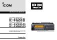
INSTRUCTION MANUAL VHF MOBILE TRANSCEIVER iF1721/D iF1821/D UHF MOBILE TRANSCEIVER iF2721/D iF2821/D This device complies with Part 15 of the FCC Rules. Operation is subject to the condition that this device does not cause harmful interference. Above photo shows the IC-F1721/D or IC-F2721/D.
IMPORTANT PRECAUTIONS READ ALL INSTRUCTIONS carefully and com- RWARNING! NEVER connect the transceiver to an AC outlet. This may pose a fire hazard or result in an electric shock. pletely before using the transceiver. SAVE THIS INSTRUCTION MANUAL — This instruction manual contains important operating instructions for the IC-F1721/D, F1821/D, F2721/D and F2821/D VHF/ UHF MOBILE TRANSCEIVERS. EXPLICIT DEFINITIONS WORD DEFINITION Personal injury, fire hazard or electric shock RWARNING may occur.
ABOUT APCO PROJECT 25 AVOID operating the transceiver without running the vehicle’s engine. The vehicle’s battery will quickly run out if the transceiver transmits while the vehicle’s engine OFF. AVOID placing the transceiver in excessively dusty environments. AVOID placing the transceiver against walls. This will obstruct heat dissipation. AVOID the use of chemical agents such as benzine or alcohol when cleaning, as they damage the transceiver surfaces.
TABLE OF CONTENTS IMPORTANT ....................................................................................... i EXPLICIT DEFINITIONS .................................................................... i PRECAUTIONS .................................................................................. i ABOUT APCO PROJECT 25 ............................................................. ii TABLE OF CONTENTS .................................................................... iii 1 PANEL DESCRIPTION .......
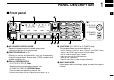
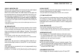
PANEL DESCRIPTION 1 ■ Front panel q 1 w e* e* Icom IC-F1721/D F2721/D Inc IC-F1821/D F2821/D o i u y t q AF VOLUME CONTROL KNOB Rotate the knob to adjust the audio output level. • Minimum audio level is pre-programmed. w FUNCTION DISPLAY (p. 2) Displays a variety of information, such as an operating channel number/name, 5-tone code, DTMF numbers and audible condition, etc. e DIAL or UP/DOWN KEYS • IC-F1721/D, F2721/D: DIAL Rotate to select an operating channel, etc.
1 PANEL DESCRIPTION y POWER SWITCH [POWER] Push to turn the power ON and OFF. • The following functions are available at power ON as options: - Automatic scan start - Password prompt - Set mode u TRANSMIT INDICATOR Lights red while transmitting. i DEALER-PROGRAMMABLE KEYS Desired functions can be programmed independently by your dealer. (p. 3) In this instruction manual, these keys are from the left, called [P0]/[P1]/[P2]/[P3]/[P4].
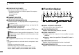
PANEL DESCRIPTION 1 ■ Programmable function keys y BELL INDICATOR Appears/blinks when the specific 2/5-tone/BIIS code is received, according to the pre-programming. u CALL CODE MEMORY INDICATOR Appears when the call code memory is selected. i SDM MEMORY INDICATOR Appears when the SDM memory is displayed. o SDM INDICATOR Appears when an SDM is received, or a transmit SDM is selected. !0 ALPHANUMERIC DISPLAY Displays an operating channel number, channel name, Set mode contents, DTMF code, etc.
1 PANEL DESCRIPTION ZONE KEY Push this key, then select the desired zone using [CH Up]/ [CH Down]. ➥ Push and hold this key for 1 sec. to indicate the scan group, then select the desired group using [CH Up]/ [CH Down]. What is “zone”?—The desired channels are assigned into a zone according to the intended use for grouping. For example, ‘Staff A’ and ‘Staff B’ are assigned into a “Business” zone, and ‘John’ and ‘Cindy’ are assigned into a “Private” zone.
PANEL DESCRIPTION PUBLIC ADDRESS KEY While in the hailer mode, push this key for the audio output via the hailer amplifier. Ask your dealer for details. While in the normal mode, the audio output via the cable can be controlled from the transceiver separately from [VOL] control knob when an optional OPC-617 ACC CABLE is installed. • This audio output can be used as a ‘public address’ function when an external audio amplifier and speaker are connected additionally.
1 PANEL DESCRIPTION RE-DIAL KEY Push to transmit the last-transmitted DTMF code. CALL KEYS Push to transmit a 2/5-tone/BIIS ID code. • Call transmission is necessary before calling another station depending on your signalling system. • [Call A] and/or [Call B] may be available when your system employs selective ‘Individual/Group’ calls. Ask your dealer which call is assigned to each key. EMERGENCY KEYS ➥ Push and hold to transmit an emergency call.
PANEL DESCRIPTION USER SET MODE KEY ➥ Push and hold to enter user set mode. • During user set mode, push this key to select an item, and change the value or condition using push [CH Up]/[CH Down]. ➥ Push and hold this key again to exit user set mode. User set mode is also available via the ‘Power ON function.’ Refer to p. 14 also. OPT 1/2/3 KEYS Push to control the output signal level from the optional unit connector.
1 PANEL DESCRIPTION SCRAMBLER/ENCRYPTION KEY (LMR (P25 Conventional) operation only) ➥ While in the analog mode operation, push to toggle the voice scrambler function ON and OFF. ➥ While in the digital mode operation, push to toggle the encryption transmission function ON and OFF. ➥ While in the mixed (digital and analog) mode operation, push to toggle the voice scrambler and encryption transmission functions ON and OFF, separately or simultaneously as below.
BASIC OPERATION 2 ■ Turning power ON ■ Channel selection q Push [ ] to turn the power ON. w If the transceiver is programmed for a start up password, input the digit codes as directed by your dealer. Several types of channel selections are available. Methods may differ according to your system set up. • 10-keypad* can be used for password input. *IC-F1821/D or IC-F2821/D only: • The keys as below can be used for password input: The transceiver detects numbers in the same block as identical.
2 BASIC OPERATION ■ Call procedure ■ Receiving and transmitting When your system employs tone signaling (excluding CTCSS and DTCS), the call procedure may be necessary prior to voice transmission. The tone signalling employed may be a selective calling system which allows you to call specific station(s) only and prevent unwanted stations from contacting you. Receiving: q Push [ ] to turn the power ON. w Push [CH Up] or [CH Down], or rotate [CH Up/Down] to select a channel, in sequence.
BASIC OPERATION 2 D Transmitting notes D TX code channel selection • Transmit inhibit function The transceiver has several inhibit functions which restrict transmission under the following conditions: - The channel is in mute condition (‘Inaudible’ condition; “ ” does not appear.) - The channel is busy. - Un-matched (or matched) CTCSS is received.
2 BASIC OPERATION D TX code number edit (PMR or BIIS PMR operation only) If the transceiver has [TX Code CH Select] or [TX Code Enter] assigned to it, TX code contents can be edited within the allowable digits. USING [TX CODE CH SELECT] KEY: q Push [TX Code CH Select] to enter the TX code channel selection mode. • Select the desired channel before entering the TX code channel selection mode if necessary. w Push [TX Code CH Select] for 1 sec. to enter the TX code edit mode.
BASIC OPERATION D Individual ID code selection (Digital mode operation only) If the transceiver has [Individual] assigned to it, the indication can be toggled between the operating channel number (or name) and Individual ID code (or name). When the Individual ID code (or name) is displayed, [CH Up], [CH Down] or [CH Up/Down] selects the desired Individual ID code. q Push [Individual]— an Individual ID code (or name) appears.
2 BASIC OPERATION ■ User set mode User set mode is accessed with [User Set Mode] and allows you to set seldom-changed settings. In this case you can “customize” the transceiver operation to suit your preferences and operating style. Entering the user set mode: q While pushing and holding [P1] and [P2], push [ ] to turn the power ON. Then, push and hold [P0] to enter user set mode. e Push [ ] again to exit set mode. [ ] User set mode is also available via a programmable key. Please refer to p.
BIIS OPERATION ■ Default setting ■ Receiving a call The following functions are assigned to each programmable key as the default. However, the assigned function can be changed by your dealer. Ask your dealer for details. During digital mode operation, BIIS is not available. NOTE: [TX Code Enter] must be assigned to a key. P0 [P0]; Call P1 P2 P3 P4 3 In this instruction manual, these keys are from the left, called [P0]/[P1]/ [P2]/[P3]/[P4].
3 BIIS OPERATION D Group call D Displaying the received call record — Queue indication q When a group call is received; • Beeps sound. •“ ” appears and the mute is released. • The programmed text message (e.g.“GROUP”) and the calling station ID (or text) is displayed when the indication mode is 2 lines. • The programmed text message (e.g.“GROUP”) and the calling station ID (or text) is displayed alternately when the indication mode is 1 line, depending on the setting.
BIIS OPERATION 3 ■ Transmitting a call A total of 3 ways for code selection are available—selecting the call code from memory, entering the call code from the keypad and calling back from the queue channel record. D Using call memory q While in the standby condition, push [P1] (Digital) to enter the call code memory channel selection mode. •“ ” appears. D Calling back from the queue channel q While in the standby condition, push [P1] (Digital) for 1 sec.
3 BIIS OPERATION D Direct code entry q While in the standby condition, push [P3] (TX Code Enter) to enter the TX code edit mode. u Push [PTT] to transmit; release to receive. i Push [P4] (Moni(Audi)) to send the ‘Clear down’ signal. • Code digit for editing blinks. 0500 w Push [P3] (TX Code Enter) to select the desired digit to be edited. • Digit for editing differs according to the setting. e Set the desired digit using [CH Up]/[CH Down]/[DIAL] or 10-keypad*.
BIIS OPERATION 3 ■ Receiving a message D Receiving a status message D Receiving an SDM (Short Data Message) q When a status message is received; q When an SDM is received; • Beeps sound. • The calling station ID (or text) and the status message is displayed alternately when the indication mode is 1 line, depending on the setting. RX Status BASE • Beeps sound. • The calling station ID (or text) and the SDM is displayed alternately when the indication mode is 1 line, depending on the setting.
3 BIIS OPERATION D Received message selection The transceiver memorizes the received message in the memory. Up to 6 messages for status and SDM, or 95 character SDM’s can be memorized. The oldest message is erased when the 7th message is received. However, once the transceiver is powered OFF, all messages are cleared. q Push [P1] (Digital) for 1 sec. • Displays queue memory. w Push [P1] (Digital) momentarily. • Displays message memory.
BIIS OPERATION 3 ■ Transmitting a status D General D Transmitting a status The status message can be selected with the programmed text, and the message text is also displayed on the function display of the called station. Up to 24 status types (1 to 24) are available, and the status messages 22 and 24 have designated meanings.
3 BIIS OPERATION ■ Transmitting an SDM (Short Data Message) D General D Transmitting an SDM The short data message, SDM, can be sent to an individual station or group stations. Also, 8 SDM memory channels are available and the messages can be edited via PC programming. q While in the standby condition, push [P1] (Digital), then push [Up] or [Down] or rotate [DIAL] to select the desired station/group code. w Push [P1] (Digital) again, then push [Up] or [Down] or rotate [DIAL] to select the desired SDM.
BIIS OPERATION D Programming an SDM memory • Available characters (IC-F1821/D or IC-F2821/D only) Key q During standby condition, push [P1] (Digital) twice, then push [Up] or [Down] to select the desired SDM to be edited. w Push [M] or [#] to enter the message editing condition. • The first character blinks when [#] is pushed, the last character blinks when [M] is pushed. •“ ” blinks. Blinks Blinks MESSAGE SDM 8 3 8 When [#] is pushed.
3 BIIS OPERATION ■ Position data transmission ■ Digital ANI When the optional cable and a GPS receiver is connected to the transceiver, the position (longitude and latitude) data can be transmitted automatically. Ask your dealer or system operator for connection details. The own ID can be transmitted each time the PTT is pushed (log-in) or released (log-off) during individual or group call communications. By receiving the ANI, the communication log can be recorded when using a PC dispatch application.
BIIS OPERATION 3 ■ Stun function ■ Priority A channel selection When the specified ID, set as a killer ID, is received, the stun function is activated. When one of the following operations is performed, the transceiver selects the Priority A channel automatically. When the killer ID is received, the transceiver switches to the password required condition. Entering of the password via the keypad is necessary to operate the transceiver again in this case.
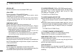
4 CONNECTION AND MAINTENANCE ■ Rear panel connection q ANTENNA CONNECTOR Connects to an antenna. Contact your dealer about antenna selection and placement. Antenna w Reserved for a future function. e EXTERNAL SPEAKER JACK Connect a 4–8 Ω external speaker. w q Supplied speaker SP-22 (IC-F1821/D or IC-F2821/D only. IC-F1721/D and IC-F2721/D has a built-in speaker.) e r y DC POWER RECEPTACLE Connects to a 12 V DC battery. Pay attention to polarities. NEVER connect to a 24 V battery.
CONNECTION AND MAINTENANCE 4 ■ Supplied Accessories Microphone DC power cable Microphone hanger and screw set Speaker* Microphone hanger cable Function name stickers • Function name stickers There are no names on the programmable function keys since the functions can be freely assigned to these keys. Attach the supplied function name stickers as below to the appropriate keys for easy recognition of that key’s assigned function.
4 CONNECTION AND MAINTENANCE ■ Mounting the transceiver ■ Optional UT-111 installation The universal mounting bracket supplied with your transceiver allows overhead mounting. • Mount the transceiver securely with the 4 supplied screws to a thick surface which can support more than 1.5 kg. Install the optional UT-111 unit as follows: Flat washer q Turn the power OFF, then disconnect the DC power cable. w Unscrew the 4 cover screws, then remove the bottom cover.
CONNECTION AND MAINTENANCE ■ Optional UT-109 or UT-110 installation 4 ■ Optional OPC-617 installation Install the OPC-617 as shown below. q Turn the power OFF, then disconnect the DC power cable. w Unscrew the 4 cover screws, then remove the bottom cover. e Cut the pattern on the PCB at the TX mic circuit (MIC) and RX AF circuit (AF OUT), then solder CP37 as shown below. r Install the scrambler unit as described in the installation of optional UT-111 installation on p.
4 CONNECTION AND MAINTENANCE ■ Antenna ■ Options A key element in the performance of any communication system is an antenna. Contact your dealer about antennas and the best places to mount them. • RMK-2 SEPARATION KIT + OPC-607/OPC-608/OPC-609 SEPARATION CABLE Allows you to install the transceiver main unit separately from the front panel for operating convenience. • SP-5/SP-22 EXTERNAL SPEAKER Input impedance : 4 Ω Max. input power : 5 W SP-5 : Large speaker for good audio quality.
SAFETY TRAINING INFORMATION W ARN ING Your Icom radio generates RF electromagnetic energy during transmit mode. This radio is designed for and classified as “Occupational Use Only”, meaning it must be used only during the course of employment by individuals aware of the hazards, and the ways to minimize such hazards. This radio is NOT intended for use by the “General Population” in an uncontrolled environment.
A-6406H-1EX-e Printed in Japan © 2004–2007 Icom Inc. Printed on recycled paper with soy ink.