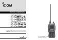
INSTRUCTION MANUAL VHF TRANSCEIVERS iF3021T/S iF3023T/S iF3026T/S UHF TRANSCEIVERS iF4021T/S iF4023T/S iF4026T/S This device complies with Part 15 of the FCC Rules. Operation is subject to the condition that this device does not cause harmful interference. The photo shows the 10-key version VHF transceiver.
IMPORTANT PRECAUTIONS READ ALL INSTRUCTIONS carefully and com- R CAUTION! NEVER hold the transceiver so that the pletely before using the transceiver. antenna is very close to, or touching exposed parts of the body, especially the face or eyes, while transmitting. The transceiver will perform best if the microphone is 2 to 4 in. (5 to 10 cm) away from the lips and the transceiver is vertical.
DO NOT modify the transceiver for any reason. KEEP the transceiver from the heavy rain, and Never immerse it in the water. The transceiver construction is water resistant, not waterproof. The use of non-Icom battery packs/chargers may impair transceiver performance and invalidate the warranty. For U.S.A. only CAUTION: Changes or modifications to this transceiver, not expressly approved by Icom Inc., could void your authority to operate this transceiver under FCC regulations.
TABLE OF CONTENTS IMPORTANT ........................................................................ i EXPLICIT DEFINITIONS ..................................................... i PRECAUTIONS ................................................................... i TABLE OF CONTENTS ...................................................... iii 1 ACCESSORIES ......................................................... 1–3 ■ Supplied accessories .................................................
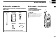
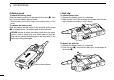
ACCESSORIES ■ Supplied accessories NOTE: Some accessories are not supplied with depending on versions. Flexible antenna Battery pack Belt clip Jack cover (with screws) Unit cover (double-sided tape)* 1 ■ Accessory attachments 1 D Flexible antenna Connect the supplied flexible antenna to the antenna connector. CAUTION! • NEVER HOLD the antenna when carrying the transceiver. • Transmitting without an antenna may damage the transceiver. *Use the unit cover as a spare. Ask your dealer for details.
1 ACCESSORIES ï Battery pack D Belt clip To attach the battery pack: Slide the battery pack in the direction of the arrow (q), then lock it with the battery release button. To attach the belt clip: q Release the battery pack if it is attached. w Slide the belt clip in the direction of the arrow until the belt clip is locked and makes a ‘click’ sound. • Slide the battery pack until the battery release button makes a ‘click’ sound.
ACCESSORIES 1 ï Jack cover 1 Attach the jack cover when the optional speaker-microphone or headset is not used. To attach the jack cover: q Attach the jack cover to the [MIC/SP] jack. w Tighten the screws. To detach the jack cover: q Unscrew the screws using a phillips screwdriver. w Detach the jack cover for the speaker-microphone or headset connection. [MIC/SP] jack q q w Jack cover w q CAUTION! • Attach the jack cover when the optional speaker-microphone or headset is not used.
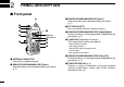
2 PANEL DESCRIPTION ■ Front panel e DEALER-PROGRAMMABLE KEY [Side1] Desired function can be programmed by your dealer. (p. 7) !0 q w e o r Speaker Microphone t i u y q ANTENNA CONNECTOR Connects the supplied antenna. w DEALER-PROGRAMMABLE KEY [Emer] Desired function can be programmed by your dealer. (p. 7) 4 r PTT SWITCH [PTT] Push and hold to transmit; release to receive. t DEALER-PROGRAMMABLE KEYS [Side2]/[Side3] Desired functions can be programmed independently by your dealer. (p.
PANEL DESCRIPTION 2 2 o EXTERNAL MICROPHONE/SPEAKER JACK Connect an optional speaker-microphone or headset. NOTE: Connect or disconnect the optional equipment after the transceiver is turned OFF. Jack cover NOTE: Attach the jack cover when the optional equipment is not used. See (p. 3) for details. !0 VOLUME CONTROL [VOL] Rotate to turn the power ON/OFF and adjusts the audio level.
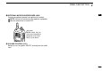
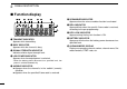
2 PANEL DESCRIPTION ■ Function display qw e r t y u y SCRAMBLER INDICATOR Appears when the voice scrambler function is activated. i o !0 q TRANSMIT INDICATOR Appears while transmitting. w BUSY INDICATOR Appears while the channel is busy. e SIGNAL STRENGTH INDICATOR Indicates relative signal strength level. r LOW POWER INDICATOR Appears when low output power is selected. • When the battery power decreases to a specified level, low power is selected automatically.
PANEL DESCRIPTION 2 ■ Programmable function keys The following functions can be assigned to [Emer], [Side1], [Side2], [Side3], [P0], [P1], [P2] and [P3] programmable function keys. Consult your Icom dealer or system operator for details concerning your transceivers programming. If the programmable function names are bracketed in the following explanations, the specific key is used to activate the function depends on the programming. CH UP AND DOWN KEYS ➥ Push to select an operating channel.
2 PANEL DESCRIPTION PRIO A/B KEYS ➥ Push to select Priority A or Priority B channel. ➥ Push and hold [Prio A (Rewrite)] or [Prio B (Rewrite)] for 1 sec. to reassign the operating channel to Priority A or Priority B channel. C.TONE CH ENT KEY Push to select the continuous tone channel using [CH Up]/[CH Down] to change the tone frequency/code setting. The selected channel remains set as the continuous tone channel until another channel is designated as such.
PANEL DESCRIPTION CALL KEYS Push to transmit a 2-tone. TX CODE CHANNEL UP/DOWN KEYS Push to select a TX code channel directly. • Call transmission is necessary before you call another station depending on your signaling system. • [Call A] and/or [Call B] may be available when your system employs selective ‘Individual/Group’ calls. Ask your dealer which call is assigned to each key. SCRAMBLER FUNCTION Push to toggle the voice scrambler function ON and OFF.
3 BASIC OPERATION ■ Turning power ON Prior to using the transceiver for the first time, the battery pack must be fully charged for optimum life and operation. (p. 16) q Rotate [VOL] to turn the power ON. w If the transceiver is programmed for a start up password, input the digit codes as directed by your dealer. • 10-keypad can be used for password input depending on version: • The keys in the table below can be used for password input: • The transceiver detects numbers in the same block as identical.
BASIC OPERATION 3 ■ Channel selection ■ Call procedure Several types of channel selections are available. Methods may differ according to your system set up. When your system employs tone signaling (excluding CTCSS and DTCS), the call procedure may be necessary prior to voice transmission. The tone signaling employed may be a selective calling system which allows you to call specific station(s) only and prevent unwanted stations from contacting you.
3 BASIC OPERATION ■ Receiving and transmitting NOTE: Transmitting without an antenna may damage the transceiver. See page 1 for accessory attachments. Receiving: q Rotate [VOL] to turn the power ON. w Push [CH Up] or [CH Down] to select the conventional system channel, in sequence. e When receiving a call, adjust the audio output level to a comfortable listening level. Transmitting: Wait for the channel to become clear to avoid interference. q Push [Call] when initiating a call from your side.
BASIC OPERATION 3 D TX code channel selection D DTMF transmission If the transceiver has [TX Code CH Select] assigned to it, the indication can be toggled between the operating channel number (or name) and TX code channel number (or name). When the TX code channel number (or name) is displayed, [CH Up] or [CH Down] selects the TX code channel. If the transceiver has [DTMF Autodial] assigned to it, the automatic DTMF transmission function is available. Up to 8 DTMF channels are available.
3 BASIC OPERATION ■ User set mode ■ Emergency transmission User set mode is accessed at power ON and allows you to set seldom-changed settings. In this case you can “customize” the transceiver operation to suit your preferences and operating style. When [Emergency Single] or [Emergency Repeat] is pushed, an emergency signal is automatically transmitted for the specified time period. Entering the user set mode: q While pushing and holding [Side2] and [Side3], rotate [VOL] to turn the power ON.
BASIC OPERATION 3 ■ Stun function When the specified ID, set as a killer ID, is received, the stun function is activated. 3 When the killer ID is received, the transceiver switches to the password required condition. Entering of the password via the keypad is necessary to operate the transceiver again in this case. ■ Priority A channel selection When one of the following operations is performed, the transceiver selects the Priority A channel automatically.
4 BATTERY CHARGING ■ Caution Misuse of Lithium-ion batteries may result in the following hazards: smoke, fire, or the battery may rupture. Misuse can also cause damage to the battery or degradation of battery performance. R DANGER! Use and charge only specified Icom battery packs with Icom radios or Icom charger. Only Icom battery packs are tested and approved for use and charge with Icom radios or Icom charger.
BATTERY CHARGING WARNING! Immediately stop using the battery if it emits an abnormal odor, heats up, or is discolored or deformed. If any of these conditions occur, contact your Icom dealer or distributor. WARNING! Immediately wash, using clean water, any part of the body that comes into contact with fluid from inside the battery. WARNING! NEVER put the battery in a microwave oven, high-pressure container, or in an induction heating cooker.
4 BATTERY CHARGING ■ Optional battery chargers ï Rapid charging with the BC-160 ï AD-106 installation The optional BC-160 provides rapid charging of optional LiIon battery packs. • An AC adapter (may be supplied with BC-160 depending on version) or the DC power cable (OPC-515L/CP-17L) is additionally required. q Install the AD-106 desktop charger adapter into the holder space of the BC-119N/BC-121N.
BATTERY CHARGING 4 ï Rapid charging with the BC-119N+AD-106 ï Rapid charging with the BC-121N+AD-106 The optional BC-119N provides rapid charging of battery packs. The following items are additionally required. • AD-106 charger adapter • An AC adapter (may be supplied with BC-119N depending on version) or the DC power cable (OPC-515L/CP-17L). The optional BC-121N allows up to 6 battery packs to be charged simultaneously. The following items are additionally required.
4 BATTERY CHARGING IMPORTANT!: Battery charging caution Ensure the guide lobs on the battery pack are correctly aligned with the guide rails inside the charger adapter. (This illustration is described with the BC-160.
5 BATTERY CASE ■ Optional battery case (BP-240) When using the optional battery case, install 6 × AAA (LR03) size alkaline batteries as illustrated at right. Fig.1 w BP-240 q Unhook the battery cover release hook (q), and open the cover in the direction of the arrow (w). (Fig.1) w Then, install 6 × AAA (LR03) size alkaline batteries. (Fig.2) 4 5 • Install the alkaline batteries only. • Be sure to observe the correct polarity. • Do not pin the ribbon under the batteries.
6 OPTIONAL SWIVEL BELT CLIP ■ MB-93 contents Qty. q Belt clip ……………………………………………………… 1 w Base clip …………………………………………………… 1 q e Clip the belt clip to a part of your belt. And insert the transceiver into the belt clip until the base clip inserted fully into the groove. w ■ Attaching r Once the transceiver is locked in place, it swivels as illustrated below. q Release the battery pack if it is attached. (p.
OPTIONAL SWIVEL BELT CLIP 6 ■ Detaching q Turn the transceiver upside down in the direction of the arrow and pull out from the belt clip. w Release the battery pack if it is attached. (p. 2) e Pinch the clip (q), and slide the base clip in the direction of the arrow (w). q w 6 CAUTION! HOLD THE TRANSCEIVER TIGHTLY, WHEN HANGING OR DETACHING THE TRANSCEIVER FROM THE BELT CLIP.
7 OPTIONS D BATTERY PACK D BELT CLIPS 1 Battery pack Voltage Capacity Battery life* BP-230N 7.4 V 980 mAh 7.35 hrs. BP-232N 7.4 V 2000 mAh 15.5 hrs. BP-240 Battery case for AAA (LR03) × 6 alkaline —*2 *1 When the power save function is turned ON, and the operating periods are calculated under the following conditions; TX : RX : standby = 5 : 5 : 90 *2 Operating period depends on the alkaline cells used.
OPTIONS 7 D OTHER OPTIONS • SP-13 EARPHONE Provides clear receive audio in noisy environment. • HM-158L/159L SPEAKER-MICROPHONE Combination speaker-microphone that provides convenient operation while hanging the transceiver from your belt. • HS-94/HS-95/HS-97 HEADSET + VS-1L VOX/PTT CASE HS-94: Ear-hook type HS-95: Neck-arm type HS-97: Throat microphone VS-1L: VOX/PTT switch box for hands-free operation, etc.
8 SAFETY TRAINING INFORMATION Your Icom radio generates RF electromagnetic energy during transmit mode. This radio is designed for and classified as “Occupational Use Only”, meaning it must be used only during the W ARN ING course of employment by individuals aware of the hazards, and the ways to minimize such hazards. This radio is NOT intended for use by the “General Population” in an uncontrolled environment.
SAFETY TRAINING INFORMATION 8 Electromagnetic Interference/Compatibility During transmissions, your Icom radio generates RF energy that can possibly cause interference with other devices or systems. To avoid such interference, turn off the radio in areas where signs are posted to do so. DO NOT operate the transmitter in areas that are sensitive to electromagnetic radiation such as hospitals, aircraft, and blasting sites.
A-6506D-1EX-w Printed in Japan © 2006 Icom Inc.