IC-F33_43GT_GS_MDC.qxd 06.7.19 2:09 PM Page a (1,1) INSTRUCTION MANUAL VHF TRANSCEIVER iF33GT/GS UHF TRANSCEIVER iF43GT/GS This device complies with Part 15 of the FCC Rules. Operation is subject to the condition that this device does not cause harmful interference.
IC-F33_43GT_GS_MDC.qxd 06.7.19 2:09 PM Page i (1,1) IMPORTANT PRECAUTION READ ALL INSTRUCTIONS carefully and com- R CAUTION! NEVER hold the transceiver so that the pletely before using the transceiver. antenna is very close to, or touching exposed parts of the body, especially the face or eyes, while transmitting. The transceiver will perform best if the microphone is 2 to 4 in. (5 to 10 cm) away from the lips and the transceiver is vertical.
IC-F33_43GT_GS_MDC.qxd 06.7.19 2:09 PM Page ii (1,1) DO NOT modify the transceiver for any reason. KEEP the transceiver from the heavy rain, and Never immerse it in the water. The transceiver construction is water resistant, not waterproof. The use of non-Icom battery packs/chargers may impair transceiver performance and invalidate the warranty. For U.S.A. only CAUTION: Changes or modifications to this transceiver, not expressly approved by Icom Inc.
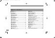
IC-F33_43GT_GS_MDC.qxd 06.7.19 2:09 PM Page iii (1,1) TABLE OF CONTENTS IMPORTANT .................................................................................... i EXPLICIT DEFINITIONS ................................................................. i PRECAUTION .................................................................................. i TABLE OF CONTENTS .................................................................. iii 1 ACCESSORIES ....................................................
IC-F33_43GT_GS_MDC.qxd 06.7.19 2:09 PM Page 1 (1,1) ACCESSORIES ■ Supplied accessories ■ Accessory attachments The following accessories are supplied: Qty. q Flexible antenna ……………………………………………1 w Battery pack …………………………………………………1 e Belt clip ………………………………………………………1 r Unit cover (double-sided tape)* ……………………………1 t Jack cover (with screws) ………………………………1 set D Flexible antenna *Use the unit cover as a spare. Ask your dealer for details.
IC-F33_43GT_GS_MDC.qxd 06.7.19 2:09 PM 1 Page 2 (1,1) ACCESSORIES ï Battery pack D Belt clip To attach the battery pack: Slide the battery pack in the direction of the arrow (q), then lock it with the battery release button. To attach the belt clip: q Release the battery pack if it is attached. w Slide the belt clip in the direction of the arrow until the belt clip is locked and makes a ‘click’ sound. • Slide the battery pack until the battery release button makes a ‘click’ sound.
IC-F33_43GT_GS_MDC.qxd 06.7.19 2:09 PM Page 3 (1,1) ACCESSORIES 1 ï Jack cover Attach the jack cover when the optional speaker-microphone is not used. To detach the jack cover: To attach the jack cover: q Attach the jack cover on q Unscrew the screws with a Phillips screwdriver. the [SP]/[MIC] jack. w Detach the jack cover for w Tighten the screws. the speaker-microphone connection.
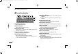
IC-F33_43GT_GS_MDC.qxd 06.7.19 2:09 PM 2 Page 4 (1,1) PANEL DESCRIPTION ■ Front panel q !1 !0 o i w e r [SP]/[MIC] JACK Connect the optional speaker-microphone. r t y u 10-keypad version q ROTARY SELECTOR Rotate to select the pre-programmed memory channels or the operating bank. (Depending on the pre-setting) w VOLUME CONTROL [VOL] Rotate to turn the power ON/OFF and adjusts the audio level. 4 e DEALER-PROGRAMMABLE KEY [RED] Desired function can be programmed by your dealer. (p.
IC-F33_43GT_GS_MDC.qxd 06.7.19 2:09 PM Page 5 (1,1) PANEL DESCRIPTION u 10-KEYPAD (Depending on version) The keypad allows you to enter digits to: • Select memory channels • Select tone channels • Select DTMF codes (during transmit) • Set TX codes • Set SmarTrunk II™/SmarTrunk 3G™ codes • Set BIIS status number • Input text message for SDM operation • Start up with the password i UP/DOWN KEYS ➥ Push to select an operating channel. ➥ Push to select a TX code channel after pushing [TX CODE CH SELECT].
IC-F33_43GT_GS_MDC.qxd 06.7.19 2:09 PM 2 Page 6 (1,1) PANEL DESCRIPTION ■ Function display q we r t y u i o !0 !1 !2 !3 q TRANSMIT INDICATOR Appears while transmitting. w BUSY INDICATOR Appears while the channel is busy. e SCROLL INDICATOR Appears when a received SDM including more than 8 characters is displayed. r SIGNAL STRENGTH INDICATOR Indicates relative signal strength level. t LOW POWER INDICATOR Appears when low output power is selected.
IC-F33_43GT_GS_MDC.qxd 06.7.19 2:09 PM Page 7 (1,1) PANEL DESCRIPTION 2 ■ Programmable function keys The following functions can be assigned to [UP], [DOWN], [P0], [P1], [P2], [P3], [RED] and [MONITOR] programmable function keys. Consult your Icom dealer or system operator for details concerning your transceivers programming. If the programmable function names are bracketed in the following explanations, the specific key is used to activate the function depends on the programming.
IC-F33_43GT_GS_MDC.qxd 06.7.19 2:09 PM 2 Page 8 (1,1) PANEL DESCRIPTION MR-CH 1/2/3/4 KEYS Push to select an operating channel directly. MONITOR KEY ➥ Mute and release the CTCSS (DTCS) or 2-tone squelch mute. Open any squelch/deactivate any mute while pushing this key. (LMR operation only) ➥ Activates one of (or two of) the following functions on each channel independently: (PMR or BIIS PMR operation only) • Push and hold to un-mute the channel (audio is emitted; ‘Audible’ condition).
IC-F33_43GT_GS_MDC.qxd 06.7.19 2:09 PM Page 9 (1,1) PANEL DESCRIPTION EMERGENCY KEYS ➥ Push and hold to transmit an emergency call. ➥ When [Emergency Single (Silent)] or [Emergency Repeat (Silent)] is pushed, an emergency call is transmitted without a beep emission and LCD indication change. • If you want to cancel the emergency call, push (or push and hold) the key again before transmitting the call.
IC-F33_43GT_GS_MDC.qxd 06.7.19 2:09 PM 2 Page 10 (1,1) PANEL DESCRIPTION STATUS UP/DOWN KEYS (BIIS operation only) ➥ While in the standby condition, push to display the transmit status indication and select a status number. ➥ When a received SDM is displayed, push to cancel the automatic scroll and scroll the message manually. ➥ When an SDM that contains more than 8 characters is displayed, push to scroll the message manually.
IC-F33_43GT_GS_MDC.qxd 06.7.19 2:09 PM Page 11 (1,1) BASIC OPERATION 3 ■ Turning power ON ■ Channel selection q Rotate [VOL] to turn the power ON. w If the transceiver is programmed for a start up password, input the digit codes as directed by your dealer. Several types of channel selections are available. Methods may differ according to your system set up.
IC-F33_43GT_GS_MDC.qxd 06.7.19 2:09 PM 3 Page 12 (1,1) BASIC OPERATION ■ Call procedure ■ Receiving and transmitting When your system employs tone signaling (excluding CTCSS and DTCS), the call procedure may be necessary prior to voice transmission. The tone signalling employed may be a selective calling system which allows you to call specific station(s) only and prevent unwanted stations from contacting you.
IC-F33_43GT_GS_MDC.qxd 06.7.19 2:09 PM Page 13 (1,1) BASIC OPERATION 3 D Transmitting notes D TX code channel selection • Transmit inhibit function The transceiver has several inhibit functions which restrict transmission under the following conditions: - The channel is in mute condition (‘Inaudible’ condition; “ ” does not appear.) - The channel is busy. - Un-matched (or matched) CTCSS is received.
IC-F33_43GT_GS_MDC.qxd 06.7.19 2:09 PM 3 Page 14 (1,1) BASIC OPERATION D TX code number edit (PMR or BIIS PMR operation only) If the transceiver has [TX Code CH Select] or [TX Code Enter] assigned to it, TX code contents can be edited within the allowable digits. TO EDIT A TX CODE VIA [TX CODE CH SELECT] KEY: q Push [TX Code CH Select] to enter the TX code channel selection mode. • Select the desired channel using [UP] or [DOWN] if necessary. w Push [TX Code CH Select] for 1 sec.
IC-F33_43GT_GS_MDC.qxd 06.7.19 2:09 PM Page 15 (1,1) BASIC OPERATION D DTMF transmission If the transceiver has [DTMF Autodial] assigned to it, the automatic DTMF transmission function is available. Up to 8 DTMF channels are available. TO SELECT A TX CODE: q Push [DTMF Autodial]— a DTMF channel appears. w Push [UP] or [DOWN] to select the desired DTMF channel. e Push [DTMF Autodial] to transmit the DTMF code in the selected DTMF channel.
IC-F33_43GT_GS_MDC.qxd 06.7.19 2:09 PM 4 Page 16 (1,1) BIIS OPERATION ■ Default setting The following functions are assigned to each programmable key as the default. However, the assigned function can be changed by your dealer. Ask your dealer for details. NOTE: [TX Code Enter] must be assigned to any key. [P0]; Call : Push to transmit a 5-tone/BIIS call when the selected channel is a 5tone or MSK channel, respectively.
IC-F33_43GT_GS_MDC.qxd 06.7.19 2:09 PM Page 17 (1,1) BIIS OPERATION D Group call q When a group call is received; • Beeps sound. • “ ” appears and the mute is released. • The programmed text message (e.g.“ ”) and the calling station ID (or text) is displayed alternately, depending on the setting. • “ ” appears or blinks depending on the setting. 4 D Displaying the received call record — Queue indication The transceiver memorizes the calling station IDs for record.
IC-F33_43GT_GS_MDC.qxd 06.7.19 2:09 PM 4 Page 18 (1,1) BIIS OPERATION ■ Transmitting a call Total of a 3 ways for code selection are available—selecting the call code from memory, entering the call code from the keypad and calling back from the queue channel record. D Calling back from the queue channel q While in the standby condition, push [P1] (Digital) for 1 sec. to enter the queue memory channel selection mode. w Push [UP] or [DOWN] to select the desired record.
IC-F33_43GT_GS_MDC.qxd 06.7.19 2:09 PM Page 19 (1,1) BIIS OPERATION 4 D Direct code entry q While in the standby condition, push [P3] (TX Code Enter) to enter the TX code edit mode. • Editable code digit blinks. u Push [PTT] to transmit; release to receive. i Push [MONITOR] (Moni(Audi)) to send the ‘Clear down’ signal. For your information When the “UpDate” setting for the call code is enabled, the set code is overwritten into the call code memory.
IC-F33_43GT_GS_MDC.qxd 06.7.19 2:09 PM 4 Page 20 (1,1) BIIS OPERATION ■ Receiving a message D Receiving a status message D Receiving an SDM q When a status message is received; q When an SDM is received; • Beeps sound. • The calling station ID (or text) and the status message is displayed alternately, depending on the setting. • Beeps sound. • The calling station ID (or text) and the SDM is displayed alternately, depending on the setting.
IC-F33_43GT_GS_MDC.qxd 06.7.19 2:09 PM Page 21 (1,1) BIIS OPERATION 4 D Received message selection The transceiver memorizes the received messages for record. Up to 6 messages for status and SDM, or 95 character SDM’s can be memorized. The oldest message is erased when the 7th message is received. However, once the transceiver is powered OFF, all messages are cleared. q Push [P1] (Digital) for 1 sec. • Displays queue memory. w Push [P1] (Digital) momentarily.
IC-F33_43GT_GS_MDC.qxd 06.7.19 2:09 PM 4 Page 22 (1,1) BIIS OPERATION ■ Transmitting a status D General D Transmitting a status The status message can be selected with the programmed text, and the message text is also displayed on the function display of the called station. Up to 24 status types (1 to 24) are available, and the status messages 22 and 24 have designated meanings.
IC-F33_43GT_GS_MDC.qxd 06.7.19 2:09 PM Page 23 (1,1) BIIS OPERATION 4 ■ Transmitting an SDM D General D Transmitting an SDM The short data message, SDM, can be sent to an individual station or group stations. Also, 8 SDM memory channels are available and the messages can be edited via PC programming. q While in the standby condition, push [P1] (Digital), then push [UP] or [DOWN] to select the desired station/group code. w Push [P1] (Digital) again, then push [UP] or [DOWN] to select the desired SDM.
IC-F33_43GT_GS_MDC.qxd 06.7.19 2:09 PM 4 Page 24 (1,1) BIIS OPERATION D Programming an SDM memory (10-keypad version is required) q During standby condition, push [P1] (Digital) twice, then push [UP] or [DOWN] to select the desired SDM to be edited. w Push [M] or [#] to enter the message editing condition. • The first character blinks when [#] is pushed, the last character blinks when [M] is pushed as below. e Push the appropriate digit key, [0] to [9], to enter the desired character.
IC-F33_43GT_GS_MDC.qxd 06.7.19 2:09 PM Page 25 (1,1) BIIS OPERATION 4 ■ Position data transmission ■ Printer connection When the optional cable and a GPS receiver is connected to the transceiver, the position (longitude and latitude) data can be transmitted automatically. Ask your dealer or system operator for connection details. When the optional cable is connected to the transceiver, a printer can be connected to print out the received SDM content and the ID of the station who sent the message.
IC-F33_43GT_GS_MDC.qxd 06.7.19 2:09 PM 4 Page 26 (1,1) BIIS OPERATION ■ Auto emergency transmission ■ BIIS indication When [Emergency Single (Silent)] or [Emergency Repeat (Silent)] is pushed, an emergency signal is automatically transmitted for the specified time period. The following indications are available for the BIIS operation on an MSK channel.
IC-F33_43GT_GS_MDC.qxd 06.7.19 2:09 PM Page 27 (1,1) BIIS OPERATION 4 ■ Man Down Emergency Call The optional UT-113 MAN DOWN UNIT is required for this function. The man down emergency call function transmits an emergency call automatically, when the transceiver has been left in a horizontal position. This function can be performed for both 5-tone and MSK channels.
IC-F33_43GT_GS_MDC.qxd 06.7.19 2:09 PM 5 Page 28 (1,1) MDC 1200 OPERATION ■ MDC 1200 system operation The MDC 1200 signaling system enhances your transceiver’s capabilities. It allows PTT ID*, Selective Calling, Call Alert, Radio Check, Messaging and Emergency signaling. Also, the dispatcher can stun and revive transceivers on the system. An additional feature of MDC 1200 found in Icom transceivers is called aliasing. Each transceiver on the system has a unique ID number.
IC-F33_43GT_GS_MDC.qxd 06.7.19 2:09 PM Page 29 (1,1) MDC 1200 OPERATION 5 D Transmitting a Call Alert D Transmitting a Radio Check Call Call Alert allows you to notify another user who may be away from the transceiver that you want to talk. Radio check call allows you to determine whether another transceiver is turned on, within range and on channel without requiring any action from the targeted station user. qPush [MDC Call] to enter the MDC menu selection mode.
IC-F33_43GT_GS_MDC.qxd 06.7.19 2:09 PM 5 Page 30 (1,1) MDC 1200 OPERATION D Transmitting a Status Message Status Messaging allows you to send a pre-programmed status message to the dispatcher. There are 16 status codes that can be sent. In addition, the dispatcher can send an MDC 1200 signal that causes the transceiver to automatically transmit its current status. qPush [MDC Call] to enter the MDC menu selection mode. wSelect “STATUS” using [CH Up], [CH Down], [MDC Up] or [MDC Down].
IC-F33_43GT_GS_MDC.qxd 06.7.19 2:09 PM Page 31 (1,1) MDC 1200 OPERATION 5 D Transmitting a Message D Emergency Calls The transceiver can send a pre-programmed message to the dispatcher. There are 16 messages that can be sent on a channel. The MDC 1200 Emergency feature can be accessed using the [MDC Emg] key (p. 10). The optional UT-113 MAN DOWN UNIT can also activate this feature.
IC-F33_43GT_GS_MDC.qxd 06.7.19 2:09 PM 5 Page 32 (1,1) MDC 1200 OPERATION D Programming station ID code (10-keypad version is required) If your transceiver is equipped with a 10-keypad, you can enter a station ID code from the keypad for the Selective Call, Call Alert or Radio Check Call functions. qPush [MDC Call] to enter the MDC menu selection mode. wSelect “SELCALL”, “RADIOCHK” or “CALALERT” using [CH Up], [CH Down], [MDC Up] or [MDC Down].
IC-F33_43GT_GS_MDC.qxd 06.7.19 2:09 PM Page 33 (1,1) MDC 1200 OPERATION 5 ■ Receiving a call D Receiving a Selective Call D Receiving a Call Alert q When an individual call is received; q When a Call Alert is received; • Beeps sound. • “ ” blinks. • The calling station ID (or alias) and “SELCALL” are displayed alternately. Blinks w Push and hold [PTT] and speak into the microphone. e Release [PTT] to receive a response. • Beeps sound. • “ ” blinks.
IC-F33_43GT_GS_MDC.qxd 06.7.19 2:09 PM 6 Page 34 (1,1) OPTIONAL SmarTrunk OPERATION ■ SmarTrunk II™, SmarTrunk 3G™ and conventional modes This transceiver is capable of SmarTrunk II™/SmarTrunk 3G™ functions. The optional UT-105/UT-117/UT-117S allow communications in conventional channels, SmarTrunk II™/SmarTrunk 3G™ channels. Select a channel bank for SmarTrunk II™/SmarTrunk 3G™ before trunking operation.
IC-F33_43GT_GS_MDC.qxd 06.7.19 2:09 PM Page 35 (1,1) OPTIONAL SmarTrunk OPERATION 6 D PTT dispatch operation*1 D Turbo SpeeDial q Push [PTT] once (without dialling) to initiate a dispatch call. w Begin talking after you hear three beeps (one short, highpitched, two very-short, low-pitched). e Receiving a dispatch call is indicated by the same threebeep sequence. To automatically dial a commonly used number with one push: • It is not necessary to push [M] to answer a dispatch call.
IC-F33_43GT_GS_MDC.qxd 06.7.19 2:09 PM 7 Page 36 (1,1) OPTIONAL UNIT INSTALLATION ■ Optional unit installation Install the optional unit as follows: q Rotate [VOL] to turn the power OFF, and remove the battery pack. (p. 2) w Remove the unit cover. r Replace the unit cover and the battery pack, then rotate [VOL] to turn the power ON. NOTE: Use a flat head screw driver or a similar flat instrument, and insert into the hollow of the chassis, then lift and take away the unit cover.
IC-F33_43GT_GS_MDC.qxd 06.7.19 2:09 PM Page 37 (1,1) OPTIONAL UNIT INSTALLATION 7 ■ UT-109 and UT-110 installation The following PC board modification is required when installing the optional UT-109 or UT-110: NOTE: When uninstalling the scrambler unit Be sure to re-solder the disconnected points at left, otherwise no TX modulation or AF output is available. q Rotate [VOL] to turn the power OFF, and remove the battery pack. (p. 2) w Remove the unit cover as shown on p.
IC-F33_43GT_GS_MDC.qxd 06.7.19 2:09 PM 7 Page 38 (1,1) OPTIONAL UNIT INSTALLATION ■ UT-105, UT-117 and UT-117S installation The following PC board modification is required when installing the optional UT-105, UT-117 or UT-117S: q Rotate [VOL] to turn the power OFF, and remove the battery pack. (p. 2) w Remove the unit cover as described in the Optional unit installation (p. 36). e Cut and solder the pattern on the PCB at the RX AF circuit as shown at right.
IC-F33_43GT_GS_MDC.qxd 06.7.19 2:09 PM Page 39 (1,1) BATTERY CHARGING 8 ■ Battery charging ■ Battery caution Prior to using the transceiver for the first time, the battery pack must be fully charged for optimum life and operation. R DANGER Charge the specified Icom batteries only. Only tested and approved for use with genuine Icom batteries. Fire and/or explosion may occur when a third party battery pack or counterfeit product is charged.
IC-F33_43GT_GS_MDC.qxd 06.7.19 2:09 PM 8 Page 40 (1,1) BATTERY CHARGING ■ Optional battery chargers ï Rapid charging with the BC-160 ï AD-106 installation The optional BC-160 provides rapid charging of optional LiIon battery packs. • An AC adapter (may be supplied with BC-160 depending on version) or the DC power cable (OPC-515L/CP-17L) is additionally required. q Install the AD-106 desktop charger adapter into the holder space of the BC-119N/BC-121N.
IC-F33_43GT_GS_MDC.qxd 06.7.19 2:09 PM Page 41 (1,1) BATTERY CHARGING 8 ï Rapid charging with the BC-119N+AD-106 ï Rapid charging with the BC-121N+AD-106 The optional BC-119N provides rapid charging of battery packs. The following items are additionally required. • AD-106 charger adapter • An AC adapter (may be supplied with BC-119N depending on version) or the DC power cable (OPC-515L/CP-17L). The optional BC-121N allows up to 6 battery packs to be charged simultaneously.
IC-F33_43GT_GS_MDC.qxd 06.7.19 2:09 PM 8 Page 42 (1,1) BATTERY CHARGING IMPORTANT!: Battery charging Ensure the guide lobs on the battery pack are correctly aligned with the guide rails inside the charger adapter. (This illustration is described with the BC-160.
IC-F33_43GT_GS_MDC.qxd 06.7.19 2:09 PM Page 43 (1,1) 9 BATTERY CASE ■ Optional battery case (BP-240) When using the optional battery case, install 6 × AAA (LR03) size alkaline batteries as illustrated at right. Fig.1 w BP-240 q Unhook the battery cover release hook (q), and open the cover in the direction of the arrow (w). (Fig.1) w Then, install 6 × AAA (LR03) size alkaline batteries. (Fig.2) • Install the alkaline batteries only. • Be sure to observe the correct polarity.
IC-F33_43GT_GS_MDC.qxd 06.7.19 2:09 PM 10 Page 44 (1,1) SWIVEL BELT CLIP ■ MB-93 contents Qty. q Belt clip ……………………………………………………… 1 w Base clip …………………………………………………… 1 q w ■ To attach q Release the battery pack if it is attached. (p. 2) w Slide the base clip in the direction of the arrow until the base clip is locked and makes a ‘click’ sound. 44 e Clip the belt clip to a part of your belt. And insert the transceiver into the belt clip until the base clip inserted fully into the groove.
IC-F33_43GT_GS_MDC.qxd 06.7.19 2:09 PM Page 45 (1,1) SWIVEL BELT CLIP 10 ■ To detach q Turn the transceiver upside down in the direction of the arrow and pull out from the belt clip. w Release the battery pack if it is attached. (p. 2) e Pinch the clip (q), and slide the base clip in the direction of the arrow (w). q w CAUTION! HOLD THE TRANSCEIVER TIGHTLY, WHEN HANGING OR DETACHING THE TRANSCEIVER FROM THE BELT CLIP.
IC-F33_43GT_GS_MDC.qxd 06.7.19 2:09 PM 11 Page 46 (1,1) OPTIONS D BATTERY PACK D BELT CLIPS Battery pack Voltage Capacity Battery life*1 BP-230 7.4 V 800 mAh 6 hrs. BP-231 7.4 V 1150 mAh BP-232 7.4 V 2000 mAh BP-240 Battery case for AAA (LR03) × 6 alkaline IC-F33GT/GS IC-F43GT/GS IC-F33GT/GS IC-F43GT/GS 9 hrs. 8 hrs. 16 hrs. 15 hrs.
IC-F33_43GT_GS_MDC.qxd 06.7.19 2:09 PM Page 47 (1,1) OPTIONS 11 D DC CABLES • CP-17L CIGARETTE LIGHTER CABLE Allows charging of the battery pack through a 12 V cigarette lighter socket. (For BC-119N) • OPC-515L/OPC-656 DC POWER CABLES Allows charging of the battery pack using a 13.8 V power source instead of the AC adapter. OPC-515L: For BC-119N OPC-656 : For BC-121N D OTHER OPTIONS • SP-13 EARPHONE Provides clear receive audio in noisy environment.
IC-F33_43GT_GS_MDC.qxd 06.7.19 2:09 PM 12 Page 48 (1,1) SAFETY TRAINING INFORMATION Your Icom radio generates RF electromagnetic energy during transmit mode. This radio is designed for and classified as “Occupational Use Only”, meaning it must be used only during the W ARN ING course of employment by individuals aware of the hazards, and the ways to minimize such hazards. This radio is NOT intended for use by the “General Population” in an uncontrolled environment.
IC-F33_43GT_GS_MDC.qxd 06.7.19 2:09 PM Page 49 (1,1) SAFETY TRAINING INFORMATION 12 Electromagnetic Interference/Compatibility During transmissions, your Icom radio generates RF energy that can possibly cause interference with other devices or systems. To avoid such interference, turn off the radio in areas where signs are posted to do so. DO NOT operate the transmitter in areas that are sensitive to electromagnetic radiation such as hospitals, aircraft, and blasting sites.
IC-F33_43GT_GS_MDC.qxd 06.7.
IC-F33_43GT_GS_MDC.qxd 06.7.
IC-F33_43GT_GS_MDC.qxd 06.7.19 2:09 PM A-6535H-1EX Printed in Japan © 2006 Icom Inc.