
Operation Manual


2
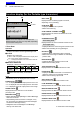
PANEL DESCRIPTION
2-6
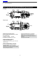
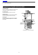
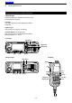
Rear panel (for the Mobile type transceiver)
ANTENNA
CONNECTOR
GPS ANTENNA
CONNECTOR
e
EXTERNAL SPEAKER JACK
r
IGNITION LEAD
t
USB CABLE
y
D-SUB 25-PIN CONNECTOR
u
DC POWER CABLE
q w
q ANTENNA CONNECTOR
Connect to an antenna.
w GPS ANTENNA CONNECTOR
Connect the UX-241 GPS antenna.
e EXTERNAL SPEAKER JACK
Connect a 4 ~ 8 Ω external speaker.
r IGNITION LEAD
Connects to an ignition line.
R Do not put pressure on this lead. Binding to the
DC power cable is recommended.
t USB CABLE
Connects to a PC.
y D-SUB 25-PIN CONNECTOR
Connects to an external unit.
NOTE: When connecting an external unit to this
connector, be sure to rmly tighten the screws.
u DC POWER CABLE
Connects to a 12 V DC battery.
Pay attention to polarities.
CAUTION: DO NOT connect to a 24 V battery.
This will damage the transceiver.
Previous view