IC-F610_MPT-2.qxd 05.5.
IC-F610_MPT-2.qxd 05.5.10 1:00 PM Page 2 (1,1) Icom, Icom Inc. and the logo are registered trademarks of Icom Incorporated (Japan) in the United states, the United Kingdom, Germany, France, Spain, Russia and/or other countries.
IC-F610_MPT-2.qxd 05.5.10 1:00 PM Page 3 (1,1) FOREWORD Thank you for purchasing this Icom product. IC-F610 UHF TRUNKED RADIO is designed and built with Icom’s superior technology and craftsmanship. With proper care, this product should provide you with years of troublefree operation. We want to take a couple of moments of your time to thank you for making the IC-F610 your radio of choice, and hope you agree with Icom’s philosophy of “technology first.
IC-F610_MPT-2.qxd 05.5.10 1:00 PM Page 4 (1,1) CAUTIONS R WARNING! NEVER connect the transceiver to an DO NOT use or place the transceiver in areas with tem- AC outlet. This may pose a fire hazard or result in an electric shock. peratures below –22°F (–30°C) or above +140°F (+60°C) or, in areas subject to direct sunlight, such as the dashboard. NEVER connect the transceiver to a power source of more than 16 V DC such as a 24 V battery. This connection will ruin the transceiver.
IC-F610_MPT-2.qxd 05.5.10 1:00 PM Page 5 (1,1) TABLE OF CONTENTS FOREWORD . . . . . . . . . . . . . . . . . . . . . . . . . . . i IMPORTANT . . . . . . . . . . . . . . . . . . . . . . . . . . . . i EXPLICIT DEFINITIONS . . . . . . . . . . . . . . . . . . i CAUTIONS . . . . . . . . . . . . . . . . . . . . . . . . . . . . ii TABLE OF CONTENTS . . . . . . . . . . . . . . . . . . iii 1 PANEL DESCRIPTION . . . . . . . . . . . . . . . 1–4 ■Front panel . . . . . . . . . . . . . . . . . . . . . . . . .
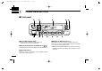
IC-F610_MPT-2.qxd 05.5.10 1:00 PM 1 Page 6 (1,1) PANEL DESCRIPTION ■ Front panel q w !2 !1 !0 o q AF VOLUME CONTROL KNOB Rotate the knob to adjust the audio output level. • Minimum audio level is pre-programmed. ∫]/[√ √] w STATUS UP/DOWN (LEFT UP/DOWN) KEYS* [∫ Pushing these keys will scroll up/down the status memory. e FUNCTION DISPLAY Displays a variety of information, such as dialling numbers, texts, status and message, etc.
IC-F610_MPT-2.qxd 05.5.10 1:00 PM Page 7 (1,1) PANEL DESCRIPTION t MEMORY DOWN (RIGHT DOWN) KEY* [ ] ➥If the stored calls are displayed by pushing the Call Back key, this key scrolls down the screen. ➥While entering the dial number via the optional microphone keypad, push the key to delete the last digit as a backspace key. y CLEAR KEY* [Clear/P4] ➥If this key is pushed during a call, the call is finished. ➥If the key is push and held down for 2.5 sec.
IC-F610_MPT-2.qxd 05.5.10 1:00 PM 1 Page 8 (1,1) PANEL DESCRIPTION ‘ Programmable key assignment Dealer programmable keys [P0], [P1], [P2], [P3], left Up/Down ∫]/[√ √] and right Up/Down [ ]/[ ] can be programmed for [∫ one of several functions by your Icom dealer. In the following explanations, programmable function names are bracketed; the specific switch used to activate the function depends on programming. [Call Back] Push this key to turn the Call Back function ON or OFF.
IC-F610_MPT-2.qxd 05.5.10 1:00 PM Page 9 (1,1) PANEL DESCRIPTION 1 ■ Function display q w e r t y u i o q TRANSMIT INDICATOR Appears while transmitting. w RECEIVE INDICATOR Appears while receiving a message. e SIGNAL STRENGTH METER Indicates the received signal strength at 4 levels. • If the connection with the communication network is not established, the whole icon turns OFF while blinks. • For a stable communication, at least the second highest level (with two bars appearing) is required.
IC-F610_MPT-2.qxd 05.5.10 1:00 PM 2 Page 10 (1,1) OPERATION ■ Turning power ON q Push to turn the power ON. • A power-up alert tone sounds for about 1 sec. and an opening message may appear. w If the transceiver is programmed for a start up passcode, input the digit codes as directed by your dealer. • The keys in the table below can be used for password input. • The transceiver detects numbers in the same block as identical. Therefore “01234” and “56789” are the same.
IC-F610_MPT-2.qxd 05.5.10 1:00 PM Page 11 (1,1) OPERATION ‘ General Push to turn the power ON. A power-up alert tone will be heard. Push again to turn the power OFF. The following information will sequentially appear on the display. D Opening text The pre-programmed opening text and individual ID will appear. The individual ID consisting of a prefix code (3 digits) + a fleet code (2 digits)+ an individual code (2 or 3 digits) will appear. (e.g.
IC-F610_MPT-2.qxd 05.5.10 1:00 PM 2 Page 12 (1,1) OPERATION t A warning beep will be emitted 10 seconds before the communication timer reaches the limit. When the limit has been reached, the communication will be disconnected automatically. TIME 1 59 communication timer reaches the limit. When the limit has been reached, the communication will be disconnected automatically. u To manually end the communication, press the [Clear] key. (or push [✱], then push [#]).
IC-F610_MPT-2.qxd 05.5.10 1:00 PM Page 13 (1,1) OPERATION t A warning sound will be emitted 10 seconds before the communication timer reaches the limit. When the limit has been reached, the communication will be disconnected automatically. y Push [Clear] to manually end the communication. D Making a Status Call A status message may be sent to the dispatcher or a remote station having an individual code. (No status message can be sent to any station using a group code.
IC-F610_MPT-2.qxd 05.5.10 1:00 PM 2 Page 14 (1,1) OPERATION r Push [PTT] to send the status message to the despatcher. t When the status message has been successfully sent out, ‘OK’ appears on the display. D Include Call • After moving to the communication channel, you can make an additional call to the other station for them join in to the communication with you. ➥Make a call with a memory individual/group call or make a call via the keypad on the communication channel to start the Include call.
IC-F610_MPT-2.qxd 05.5.10 1:00 PM Page 15 (1,1) OPERATION D Group Call • Group Call to the stations having the same prefix and fleet codes. Enter the group code via the keypad and then push [#]. The group call will be started. (e.g.) To call 200 5001 91 from 200 2001 200, enter 91#. • Group Call to the stations having the same prefix code and a different fleet code. Enter the fleet code plus the group code via the keypad and then push [#]. The group call will be started. (e.g.
IC-F610_MPT-2.qxd 05.5.10 1:00 PM 2 Page 16 (1,1) OPERATION D Emergency Call • Enter ✱9✱ plus an individual code or a group code and then push [#]. The emergency call will be started. ‘Selectable Emergency Function; Disable*’ ➥Enter ✱9, then push [#]. The pre-programmed ‘Emergency Number’ used for the emergency call. ‘Selectable Emergency Function; Enable*’ ➥Enter ✱9, then push [#]. The current ‘Dial Number’ selected via [ ]/[ ] used for the emergency call.
IC-F610_MPT-2.qxd 05.5.10 1:00 PM Page 17 (1,1) OPERATION • Enter #44n✱ plus station B’s individual code and then push [#]. This will allow you to cancel the Divert 3rd Party call. • Enter #45n and then push [#]. This will allow you to cancel the call that diverted to you. ➥In the place of ‘n’, enter 1 for voice, 0 for data, or nothing for both voice and data. D SDM (Short Data Message) Call • Enter ✱2✱ plus data (up to 24 digits in total) via the keypad and then push [#].
IC-F610_MPT-2.qxd 05.5.10 1:00 PM 3 Page 18 (1,1) RECEIVING r To end the communication manually, push [Clear] or push [✱] then [#]. t The transceiver will return to the waiting mode. ‘ Receiving a call D Reception of an individual call When an individual call is received, the telephone beep sounds telling you that a call has been received. Immediately after this, you can talk with the caller. ALERTING 302 *Message and individual code displayed alternately.
IC-F610_MPT-2.qxd 05.5.10 1:00 PM Page 19 (1,1) RECEIVING ➥ In the case of a call received from the Inter-Prefix, ‘INTER-PFIX’ is displayed on the LCD screen. ➥The communication time timer will appear on the display. TIME 00 56 w The individual ID will appear if ‘Display Pressel’ function is enabled, and remain displayed during the current communication. e Pushing [PTT] will allow you to talk with the caller. ➥In the case of a group call, the communication only can be cleared down from the caller’s side.
IC-F610_MPT-2.qxd 05.5.10 1:00 PM 3 Page 20 (1,1) RECEIVING ‘ Progress messages The following messages appear corresponding to the progress of the processing of a call. MESSAGE DESCRIPTION ABORTED . . . . . .Your call has been aborted (Wait for a while and then make the call again). CALLING . . . . . . .Your call is now being processed. CALL BACK . . . . .Your call has been recorded at the called station (Wait for a reply). DIVERTED . . . . .Your call has been diverted to another station. ENGAGED .
IC-F610_MPT-2.qxd 05.5.10 1:00 PM Page 21 (1,1) OTHER FUNCTION D Call Back function • If you do not want to answer the call immediately, use this function. ➥Pushing [Call Back] will allow you to enable or disable the function. • When this function is enabled, the transceiver sends the Call Back to the called station.
IC-F610_MPT-2.qxd 05.5.10 1:00 PM 4 Page 22 (1,1) OTHER FUNCTION D Scrambler function The transceiver is compatible with the optional UT-109 (#02)* scrambler unit. ➥ Pre-programmed 5 scrambler code can be selected in the User Setup Menu. (p. 19) NOTE: UT-109 is recommended for trunking operation. Both UT-110 and UT-109 are recommended for conventional operation. D Compander function The compander function provides clear audio quality in noisy environments. (p.
IC-F610_MPT-2.qxd 05.5.10 1:00 PM Page 23 (1,1) OTHER FUNCTION 4 D RX Speaker function (optional OPC-617 is required) Output the receive audio to an out-of-vehicle speaker. External audio amplifier and speaker are required. D Ignition SW function The transceiver’s power turns ON/OFF automatically depending on the ignition switch position. This function requires additional optional wiring cables. Please consult your dealer.
IC-F610_MPT-2.qxd 05.5.10 1:00 PM 5 Page 24 (1,1) USER SETUP MENU ‘ User Setup Menu By pushing and holding down the [Clear/P4] key for 2.5 seconds when your transceiver is in the standby mode (not during communication, dialling, or operation), the User Setup menu appears. The User Setup menu allows you to use the settings for the backlight, Ringer level, beep level, compander ON/OFF, microphone gain, squelch level, AF minimum level, Scrambler, Hook and Horn settings.
IC-F610_MPT-2.qxd 05.5.10 1:00 PM Page 25 (1,1) MAP27 6 ‘ MAP27 serial interface MAP27 is a Mobile Access Protocol for MPT1327/1343 communication equipment. It permits data exchange between MPT radio equipment and external equipment such as a data terminal which may be a laptop computer. By connecting the OPC-822 OPTIONAL INTERFACE CABLE to the external connector of the transceiver (J9), you can use the serial interface*. (See right.
IC-F610_MPT-2.qxd 05.5.10 1:00 PM 7 Page 26 (1,1) CONVENTIONAL MODE ‘ Conventional Mode operation ‘ Programmable key assignment This transceiver has conventional mode capability. You can use up to 32 pre-programmed conventional channels. These channels can be selected with the [ ] or [ ]. Dealer programmable keys [P0], [P1], [P2], [P3], [P4], [OP F0], ∫], [√ √], [ ] and [ ] can be pro[OP F1], [OP F2], [∫ grammed for one of several functions by your Icom dealer.
IC-F610_MPT-2.qxd 05.5.10 1:00 PM Page 27 (1,1) CONVENTIONAL MODE 7 Either Trunking or Conventional mode; [Mode] Push this key to toggle between Trunking mode and Conventional mode. [Null] No function is assigned. [High/Low] Pushing this key will toggle in the order of Low1 power, Low2 power, High power and Auto power. [Public Address] Use the transceiver as an amplifier. [RX Speaker] Output the receive audio to an out of vehicle speaker.
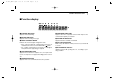
IC-F610_MPT-2.qxd 05.5.10 1:00 PM 8 Page 28 (1,1) CONNECTION AND MAINTENANCE ■ Rear panel and connection Optional speaker (SP-22) w q Antenna r red: t Optional cable (OPC-617 or OPC-822) e black: NEVER connect to a 24 V battery. 12V Battery Supplied DC power cable Crimp Note: Use the terminals for the cable connections.
IC-F610_MPT-2.qxd 05.5.10 1:00 PM Page 29 (1,1) CONNECTION AND MAINTENANCE q ANTENNA CONNECTOR Connects to an antenna. Ask your Dealer about antenna selection and placement. w MICROPHONE HANGER Connect the supplied microphone hanger to the vehicle’s ground for microphone on/off hook functions. ■ Supplied Accessories t OPTIONAL CABLE (OPC-617 or OPC-822) Connect an external horn drive unit, LCD backlight control, etc. e w q r OM IC e DC POWER RECEPTACLE Connects to a 12 V DC battery.
IC-F610_MPT-2.qxd 05.5.10 1:00 PM 8 Page 30 (1,1) CONNECTION AND MAINTENANCE ■ Mounting the transceiver The front panel can be inverted for correct viewing while leaving the built-in speaker facing away from the mounting surface. r Invert the transceiver 180 degrees clockwise as below. t Re-attach the Front panel to the transceiver. y Tighten the 2 screws. D Inverting the Front panel CAUTION: • NEVER rotate the transceiver more than 180 degrees. • DO NOT bend the flat cable too hard.
IC-F610_MPT-2.qxd 05.5.10 1:00 PM Page 31 (1,1) CONNECTION AND MAINTENANCE D Mounting the transceiver The universal mounting bracket supplied with your transceiver allows overhead mounting. • Mount the transceiver securely with the 4 supplied screws to a thick surface which can support more than 1.5 kg. Flat washer 8 ■ Optional UT-109 /UT-110 installation q Turn power OFF, then disconnect the DC power cable. w Unscrew the 4 screws, then remove the bottom cover.
IC-F610_MPT-2.qxd 05.5.10 1:00 PM 8 Page 32 (1,1) CONNECTION AND MAINTENANCE ■ Optional OPC-617 installation ■ Antenna Install the OPC-617 as shown below. A key element in the performance of any communication system is an antenna. Ask your Dealer about antennas and the best places to mount them. ■ Fuse replacement Two fuses are installed in the supplied DC power cable.
IC-F610_MPT-2.qxd 05.5.10 1:00 PM Page 33 (1,1) CLONING 9 ‘ Cloning Cloning allows you to quickly and easily transfer the programmed contents from one transceiver to another transceiver; or data from PC to a transceiver using the optional CS-F600(MPT) CLONING SOFTWARE. PC-to-transceiver cloning Please refer to the HELP file that comes with the CS-F600(MPT) CLONING SOFTWARE. CAUTION: Imprudent cloning operation causes a cloning error. In such a case, memory contents may be lost.
IC-F610_MPT-2.qxd 05.5.10 1:00 PM 10 Page 34 (1,1) OPTIONS SP-22 EXTERNAL SPEAKER Compact and easy to install. Input impedance: 4 Ω Max. input power: 5 W HM-100TN DTMF microphone. SM-25 Desktop microphone. UT-109/UT-110 (#02) VOICE SCRAMBLER UNIT • UT-109: Non-rolling type (max. 32 codes) Recommended for trunking mode. • UT-110: Rolling type (max. 1020 codes) Recommended both trunking and conventional mode. OPC-617 ACC CABLE Allows you to connect to an external terminal.
IC-F610_MPT-2.qxd 05.5.10 1:00 PM Page 35 (1,1) CE DECLARATION OF CONFORMITY We Icom Inc. Japan 1-1-32, Kamiminami, Hirano-ku Osaka 547-0003, Japan Declare on our sole responsibility that this equipment complies with the essential requirements of the Radio and Telecommunications Terminal Equipment Directive, 1999/5/EC, and that any applicable Essential Test Suite measurements have been performed. Kind of equipment: UHF TRANSCEIVER Type-designation: iC-f610 440—490 MHz 12.5 KHz/ 25 KHz 440—490 MHz 12.
IC-F610_MPT-2.qxd 05.5.10 1:00 PM Page 36 (1,1) < Intended Country of Use > GER AUT GBR IRL A-6163H-1EU-w Printed in Japan © 2002–2005 Icom Inc.