IC-F510 Series_BIIS-2.qxd 06.7.
IC-F510 Series_BIIS-2.qxd 06.7.13 1:31 PM Page i (1,1) New2001 IMPORTANT READ ALL INSTRUCTIONS carefully and completely before using the transceiver. SAVE THIS INSTRUCTION MANUAL— This instruction manual contains important operating instructions for the IC-F510 VHF TRANSCEIVER and IC-F610 UHF TRANSCEIVER. EXPLICIT DEFINITIONS WORD DEFINITION Personal injury, fire hazard or electric shock R WARNING! may occur. CAUTION NOTE Equipment damage may occur. Recommended for optimum use.
IC-F510 Series_BIIS-2.qxd 06.7.13 1:31 PM Page ii (1,1) New2001 TABLE OF CONTENTS DO NOT use or place the transceiver in areas with temperatures below –25°C or above +55°C or, in areas subject to direct sunlight, such as the dashboard. AVOID operating the transceiver without running the vehicle’s engine. The vehicle’s battery will quickly run out if the transceiver is in transmission while the vehicle’s engine OFF. AVOID placing the transceiver in excessively dusty environments.
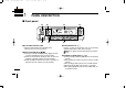
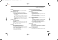
IC-F510 Series_BIIS-2.qxd 06.7.13 1:31 PM Page 1 (1,1) New2001 1 PANEL DESCRIPTION ■ Front panel q u w e y q AF VOLUME CONTROL KNOB Rotate the knob to adjust the audio output level. • Minimum audio level is pre-programmed. Y]/[Z Z] w STATUS UP/DOWN KEYS [Y ➥ During the standby condition, push to display the transmit status indication and select a status number. ➥ When a received SDM is displayed, push to cancel the automatic scroll and scroll the message manually.
IC-F510 Series_BIIS-2.qxd 06.7.13 1:31 PM Page 2 (1,1) New2001 PANEL DESCRIPTION t DEALER-PROGRAMMABLE KEYS [P0] to [P4] Desired functions can be programmed independently by your Dealer. However, the following functions are assigned as the default for BIIS operation. [P0] : [CALL] Push to transmit a 5-tone/BIIS call. • Call transmission is necessary before you call another station, depending on your signalling system.
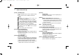
IC-F510 Series_BIIS-2.qxd 06.7.13 1:31 PM Page 3 (1,1) New2001 1 PANEL DESCRIPTION ■ Function display qw e r t y u i o !0 !1 !2 !3 q TRANSMIT INDICATOR Appears while transmitting. w RECEIVE INDICATOR Appears when a signal is received, or the squelch is open. e SIGNAL STRENGTH INDICATOR Shows the relative signal strength while receiving signals. r OUTPUT POWER INDICATOR Appears when Low 2 or Low 1 is selected.
IC-F510 Series_BIIS-2.qxd 06.7.13 1:31 PM Page 4 (1,1) New2001 PANEL DESCRIPTION ■ Programmable function keys The following functions can be assigned to [P0], [P1], [P2], Y], [Z Z], [ ] and [ ] programmable function [P3], [P4], [Y keys. Consult your Icom Dealer or System operator for details concerning your transceivers programming. In the following explanations, programmable function names are bracketed, the specific switch used to activate the function depends on programming.
IC-F510 Series_BIIS-2.qxd 06.7.13 1:31 PM Page 5 (1,1) New2001 1 PANEL DESCRIPTION [MONI (Audi)] MONITOR KEY Activates one of (or two of) the following functions on each channel independently: • Push and hold to un-mute the channel (audio is emitted; ‘Audible’ condition). • Push to toggle the mute and un-mute conditions (toggles ‘Audible’ and ‘Inaudible’). • Push to mute the channel (sets to ‘Inaudible’ only). • Push to un-mute the channel (sets to ‘Audible’ only).
IC-F510 Series_BIIS-2.qxd 06.7.13 1:31 PM Page 6 (1,1) New2001 PANEL DESCRIPTION [RE-DIAL] DTMF RE-DIAL KEY Push this key to transmit the last-used DTMF code. [TX CODE CH Up], [TX CODE CH Down] TX CODE CHANNEL UP/DOWN KEYS Push to select a TX code channel directory. [EMER] EMERGENCY KEY ➥ Push and hold to transmit an emergency call. ➥ When [EMER (Silent)] is pushed, an emergency call is transmitted without a beep emission and LCD indication change.
IC-F510 Series_BIIS-2.qxd 06.7.13 1:31 PM Page 7 (1,1) New2001 1 PANEL DESCRIPTION [SCRM] SCRAMBLER KEY ➥ Push and hold to turn the voice scrambler function ON. ➥ Push to turn the voice scrambler function OFF. NOTE: • Optional UT-109 (#02) or UT-110 (#02) SCRAMBLER UNIT is required. VOICE - UT-109: Non-rolling type. 32 codes are available. - UT-110: Rolling type. Provides higher communication security. 1020 (4 groups × 255) codes are available. • This transceiver requires version #02 unit.
IC-F510 Series_BIIS-2.qxd 06.7.13 1:31 PM Page 8 (1,1) OPERATION 2 ■ Turning power ON ■ Channel selection q Push [ Several types of channel selections are available. Methods may differ according to your system set up. ] to turn the power ON. • A power-up alert tone sounds for about 1 sec. and an opening message may appear. w If the transceiver is programmed for a start up passcode, input digit codes as directed by your Dealer.
IC-F510 Series_BIIS-2.qxd 06.7.13 1:31 PM Page 9 (1,1) New2001 2 OPERATION ■ Receiving and transmitting RECEIVING: q Push [ ] to turn the power ON. w Push [CH UP] or [CH DN] to select a channel. e When receiving a call, adjust the audio output level to a comfortable listening level. TRANSMITTING: r Take the microphone off hook. • 5-tone mute may be released (the ‘audible’ condition is selected and “ ” appears). • A priority channel may be selected automatically.
IC-F510 Series_BIIS-2.qxd 06.7.13 1:31 PM Page 10 (1,1) New2001 OPERATION 2 D Tx code channel selection D User set mode If the transceiver has a [TX CODE CH UP] or [TX CODE CH DN] key, the programmed Tx code channel can be selected directly. User set mode is accessed at power ON and allows you to set seldom-changed settings. In this case you can “customize” transceiver operation to suit your preferences and operating style.
IC-F510 Series_BIIS-2.qxd 06.7.13 1:31 PM Page 11 (1,1) New2001 3 BIIS OPERATION ■ Default setting The following functions are assigned to each programmable switch as the default. Ask your dealer for details. [P0]; CALL : Push to send a 5-tone call or BIIS call when the selected channel is a 5-tone or MSK channel, respectively. [P1]; DIGITAL : Push to select the call list ID/transmit message, or to display the receive message record for selection. [P2], [P3]; Null : No function is assigned.
IC-F510 Series_BIIS-2.qxd 06.7.13 1:31 PM Page 12 (1,1) New2001 BIIS OPERATION D Group call q When a group call is received; • Beeps sound. • “ ” appears and the mute is released. • The programmed text message (e.g. “ ”) and the calling station ID (or text) is displayed alternately. • “ ” appears or blinks depending on the setting. 3 D Displaying the received call record — Queue indication The transceiver memorizes the calling station IDs for record.
IC-F510 Series_BIIS-2.qxd 06.7.13 1:31 PM Page 13 (1,1) New2001 3 BIIS OPERATION ■ Transmitting a call A total of 3 ways for code selection are available— selecting the call code from memory, entering the call code from the keypad and calling back from the queue channel record. D Calling back from the queue channel qDuring standby condition, push [DIGITAL (P1)] for 1 sec. to select queue memory. w Push [ ]/[ ] to select the desired record.
IC-F510 Series_BIIS-2.qxd 06.7.13 1:31 PM Page 14 (1,1) New2001 BIIS OPERATION 3 D Direct code entry qDuring standby condition, push [TX CODE ENT] to select call code entering condition. Queue memory content is displayed. wSelect the desired code number via [ [TX CODE ENT]. ]/[ ] then push • Programmable digit number differs according to the setting. • When the optional DTMF microphone is used, push the appropriate digit key, [0] to [9], to set the desired code.
IC-F510 Series_BIIS-2.qxd 06.7.13 1:31 PM Page 15 (1,1) New2001 3 BIIS OPERATION ■ Receiving a message D Receiving a status message D Receiving an SDM q When a status message is received; • Beeps sound. • The calling station ID (or text) and the status message is displayed alternately. q When a status message is received; • Beeps sound. w Push [MONI (P4)] to return to standby condition.
IC-F510 Series_BIIS-2.qxd 06.7.13 1:31 PM Page 16 (1,1) New2001 BIIS OPERATION 3 D Received message selection The transceiver memorizes the received messages for record. Up to 6 messages for status and SDM, or 192 character SDM’s can be memorized, and the oldest message is erased when the 7th message is received. However, once the transceiver is powered OFF, the all messages are cleared.
IC-F510 Series_BIIS-2.qxd 06.7.13 1:31 PM Page 17 (1,1) New2001 3 BIIS OPERATION ■ Transmitting a status D General D Select a status from status memory The status message can be selected with the programmed text, and the message text is also displayed on the function display of the called station. Up to 24 status types (1 to 24) are available, and the status message 19, 22, 23 and 24 have designated meanings.
IC-F510 Series_BIIS-2.qxd 06.7.13 1:31 PM Page 18 (1,1) New2001 BIIS OPERATION 3 ■ Transmitting an SDM D General D Transmitting an SDM A short data message, SDM, can be input directly (max. 10 characters), and sent to an individual station or group stations. Also, 8 SDM memory channels are available and the messages can be edited via the optional DTMF microphone’s keypad or PC programming. qDuring standby condition, push [DIGITAL (P1)], then push [ ]/[ ] to select the desired station/group code.
IC-F510 Series_BIIS-2.qxd 06.7.13 1:31 PM Page 19 (1,1) New2001 3 BIIS OPERATION D Programming an SDM memory (optional DTMF microphone required) qDuring standby condition, push [DIGITAL (P1)] twice, then push [ ]/[ ] to select the desired SDM to be edited. w Push [✱] or [#] to enter the message editing condition. • The first character blinks when [#] is pushed, the last character blinks when [✱] is pushed as below. ePush the appropriate digit key, [0] to [9], to enter the desired character.
IC-F510 Series_BIIS-2.qxd 06.7.13 1:31 PM Page 20 (1,1) New2001 BIIS OPERATION 3 ■ Position data transmission ■ Printer connection When the optional OPC-822 INTERFACE CABLE and a GPS receiver is connected to the transceiver, the position (longitude and latitude) data can be transmitted automatically. Ask your dealer or system operator for connection details.
IC-F510 Series_BIIS-2.qxd 06.7.13 1:31 PM Page 21 (1,1) New2001 3 BIIS OPERATION ■ Auto emergency transmission ■ BIIS indication When [EMER (Silent)] is pushed, an emergency signal is automatically transmitted for the specified time period. The following indications are available for the BIIS operation on an MSK channel. The status 22 (Emergency) is sent to the selected ID station, and the position data is transmitted after the emergency signal when a GPS receiver is connected to the transceiver.
IC-F510 Series_BIIS-2.qxd 06.7.13 1:31 PM Page 22 (1,1) New2001 BIIS OPERATION 3 ■ Priority A channel selection When one of the following operations is performed, the transceiver selects the Priority A channel automatically. Priority A is selected when; • Clear down signal is received/transmitted - Set the “Move to PrioA CH” item as “Clear Down.” • Turning the power ON The Priority A channel is selected each time the transceiver power is turned ON.
IC-F510 Series_BIIS-2.qxd 06.7.13 1:31 PM Page 23 (1,1) New2001 4 SmarTrunk II™ OPERATION ■ SmarTrunk II™ and conventional modes This transceiver is capable of SmarTrunk II™ functions. The optional UT-105 allows communication in conventional channels or SmarTrunk II™ channels. Select a channel bank for SmarTrunk II™ before trunking operation. • Push [BANK] several times to select a channel bank for conventional channels or SmarTrunk II™ channels.
IC-F510 Series_BIIS-2.qxd 06.7.13 1:31 PM Page 24 (1,1) New2001 SmarTrunk II™ OPERATION 4 D Terminating a call D System busy indication After completing a call, push [#] to disconnect (hang up). If all channels are busy, three low beeps sound after you initiate a call. Try the call again later. IMPORTANT: If one person in the conversation terminates a call, all participants will be cut off. D Last number re-dial Push [✱] 2 times to automatically re-dial the last called number.
IC-F510 Series_BIIS-2.qxd 06.7.13 1:31 PM Page 25 (1,1) New2001 5 CONNECTION AND INSTALLATION ■ Rear panel description and connections Optional speaker (SP-22) w q Antenna r Red: + t Optional cable (OPC-617/822) e Black: _ 12 V Battery NEVER connect to a 24 V battery. This could damage the transceiver. Crimp NOTE: Use the terminals for the cable connection.
IC-F510 Series_BIIS-2.qxd 06.7.13 1:31 PM Page 26 (1,1) New2001 CONNECTION AND INSTALLATION q ANTENNA CONNECTOR Connects to an antenna. Ask your dealer about antenna selection and optimal antenna locations. ■ Supplied accessories q w e w MICROPHONE HANGER Connects the supplied microphone hanger to the vehicle’s ground for the hanger function. r e DC POWER RECEPTACLE Connects to a 12 V DC battery. Pay attention to polarities. NEVER connect to a 24 V battery. This could damage the transceiver.
IC-F510 Series_BIIS-2.qxd 06.7.13 1:31 PM Page 27 (1,1) New2001 5 CONNECTION AND INSTALLATION ■ Mounting the transceiver The front panel can be inverted for correct viewing while leaving the built-in speaker facing away from the mounting surface. D Inverting the Front panel q Unscrew the 2-side screws. w Detach the Front panel forward from the transceiver. e Bend the flat cable between the Front panel and main unit as shown in the following diagram.
IC-F510 Series_BIIS-2.qxd 06.7.13 1:31 PM Page 28 (1,1) New2001 CONNECTION AND INSTALLATION D Mounting the transceiver The universal mounting bracket supplied with your transceiver allows overhead mounting. • Mount the transceiver securely with the 4 supplied screws to a thick surface which can support more than 1.5 kg. 5 ■ Optional unit installation D UT-105/UT-117 installation Install the optional unit UT-105 or UT-117, provides SmarTrunk II™ or SmarTrunk 3G™ function, as below.
IC-F510 Series_BIIS-2.qxd 06.7.13 1:31 PM Page 29 (1,1) New2001 5 CONNECTION AND INSTALLATION D UT-109/UT-110/UT-117S installation D OPC-617/822 installation Install the optional unit as below. Either the optional OPC-617 FACE CABLE can be installed. q Turn power off, then disconnect the DC power cable. w Unscrew the 4 screws, then remove the bottom cover. eCut the print patterns on the PCB at the transmit mic circuit (MIC) and receive AF circuit (AFO) as shown in the diagram below.
IC-F510 Series_BIIS-2.qxd 06.7.13 1:31 PM Page 30 (1,1) New2001 CONNECTION AND INSTALLATION ■ Antenna • Connector information OPC-617 Pin Assignment trewq oiuy q LCD backlit cont. IN w AF OUT e Det. AF OUT r Mod. IN t PTT control IN y Horn drive cont. OUT u AF GND i Det. AF GND o Mod. GND OPC-822 Pin Assignment trewq oiuy q N.C. w RX D e TX D r DTR t GND 5 y DSR u RTS i CTS o N.C. A key element in the performance of any communication system is an antenna.
IC-F510 Series_BIIS-2.qxd 06.7.13 1:31 PM Page 31 (1,1) New2001 New2001 6 OPTIONS UT-105 SmarTrunk II™ LOGIC BOARD For SmarTrunk II™ operation. UT-117/UT-117S* SmarTrunk 3G™ LOGIC BOARD For SmarTrunk 3G™ operation. *In addition to SmarTrunk 3G™ capabilities, UT-117S supports the voice scrambler capability. NOTE: The optional CS-F500 CLONING SOFTWARE Rev. 2.1 or later is required. UT-108 DTMF DECODER UNIT Provides pager and code squelch capabilities.
IC-F510 Series_BIIS-2.qxd 06.7.13 1:31 PM Page 32 (1,1) New2001 7 DOC DECLARATION OF CONFORMITY We Icom Inc. Japan 1-1-32, Kamiminami, Hirano-ku Osaka 547-0003, Japan Declare on our sole responsibility that this equipment complies with the essential requirements of the Radio and Telecommunications Terminal Equipment Directive, 1999/5/EC, and that any applicable Essential Test Suite measurements have been performed.
IC-F510 Series_BIIS-2.qxd 06.7.13 1:31 PM Page 33 (1,1) New2001 < Intended Country of Use > GER AUT GBR IRL NOR A-6249D-1EU-w Printed in Japan © 2003–2006 Icom Inc.