INSTRUCTION MANUAL VHF FM REPEATER iFR3100 UHF FM REPEATER iFR4100
IMPORTANT READ THIS INSTRUCTION MANUAL CAREFULLY before attempting to operate the repeater. EXPLICIT DEFINITIONS WORD DEFINITION R WARNING Personal injury, fire hazard or electric shock may occur. SAVE THIS INSTRUCTION MANUAL– This CAUTION manual contains important safety and operating instructions for the IC-FR3100/FR4100 series. NOTE Equipment damage may occur. If disregarded, inconvenience only. No risk of personal injury, fire or electric shock.
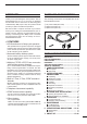
FORWARD SUPPLIED ACCESSORIES Thank you for purchasing this Icom product. The ICFR3100/FR4100 VHF/UHF FM REPEATER is designed and built with Icom’s state of the art technology and craftsmanship. With proper care, this product should provide you years of trouble-free operation.
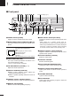
1 PANEL DESCRIPTION ■ Front panel !9 !8 !7 !6 !5 !4 !3 !2 !1 Function display (p. 2) q w e r t y q POWER SWITCH [POWER] Toggle to turn the repeater power ON or OFF. w MICROPHONE/SPEAKER CONNECTOR [MIC/SP] This 8-pin modular jack accepts the optional microphone. q i q +9 V DC output (Max.
1 PANEL DESCRIPTION !6 ANI CLEAR SWITCH [ANI CLR] Push for 1 sec. to clear the received ANI ID indication on the display and return to the original indication. NOTE: This switches’ function is not available for some versions. DFunction display !7 DEALER-PROGRAMMABLE SWITCH [PROG] Toggles the pre-programmed function ON or OFF when pushed. q MEMORY CHANNEL INDICATOR Shows the selected memory channel. 32HH@HICOMHINC. w e q r w TRANSMIT POWER INDICATOR Shows the output power level.
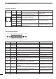
1 PANEL DESCRIPTION D Remote connector Pin No. Pin Name 1 –PTT 2 +PTT 3 –AFOUT 4 +AFOUT 5 –EXTMOD 6 +EXTMOD 7 –BUSY 8 +BUSY i q Description Specification Input terminals to transmit the repeater in relaHigh voltage=PTT ON (transmits) tion to the external equipment. An opto-isolator Hi-Z=PTT OFF is provided to facilitate PTT signals. Output terminal for AF signals from the AF detector circuit via the bandpass filter.
1 PANEL DESCRIPTION Accessory connector (continued) Pin No. Pin Name 15 M/S OUT 16 Description Specification Output terminal for master/slave signal. Open collector=OFF, 0V=ON D0 Input terminal for selecting memory channel. +5 V pull up, Active=L 17 D2 Input terminal for selecting memory channel. +5 V pull up, Active=L 18 D4 Input terminal for selecting memory channel. +5 V pull up, Active=L 19 EXT PTT Input terminal for PTT signal.
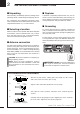
2 INSTALLATION AND CONNECTIONS ■ Unpacking ■ Duplexer After unpacking, immediately report any damage to the delivering carrier or dealer. Keep the shipping cartons. A duplexer is separately required when only one antenna is used for both transmitting and receiving. Select a duplexer according to the transmitting and receiving frequencies. Ask your Dealer for details. For a description and a diagram of accessory equipment included with the IC-FR3100/FR4100 series, see ‘Supplied Accessories’ on p.
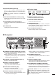
INSTALLATION AND CONNECTIONS 2 ■ Required connections HM-100N/TN HAND MICROPHONE (optional) SM-25 DESKTOP MICROPHONE (optional) MICROPHONE CONNECTOR (Front panel view) q +9 V DC output (Max. 10 mA) w I/O port for PC programming e NC r M PTT (Input port for TX control) t Microphone ground y Microphone input u Ground i M MONI (Input port for monitor control) i q CAUTION: DO NOT short pin 1 to ground as this can damage the internal 9 V regulator. DC voltage is applied to pin 1 for microphone operation.
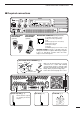
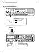
2 INSTALLATION AND CONNECTIONS ■ Advanced connections LINE CONNECTOR (Front panel view) to telephone connector q r q NC (No connection) w L1 input/output e L2 input/output r NC (No connection) Telephone connector type is different for some countries. EXTERNAL SPEAKER icom sp-7 Use a 4 Ω speaker. BATTERY AC EXT SP REMOTE TX/TX•RX ACC RX GND 7 [REMOTE] (p. 3) ACC CONNECTOR (pgs. 3, 4) Used for external equipment control. Used for external equipment control.
INSTALLATION AND CONNECTIONS ■ Power ■ Mounting the repeater Make sure the [POWER] switch is turned OFF when connecting an AC power cable and a backup battery (emergency power supply). D Using the optional MB-78 The IC-FR3100/FR4100 series can operate with an AC or DC power supply. If AC power is interrupted when operating the repeater with an AC power supply, power is automatically provided to the [BATTERY] terminals.
2 INSTALLATION AND CONNECTIONS • Top side installation q Remove the screws (M4 × 8) from both sides of the MB-78. w Remove the handles from the bottom bar. And turn the handles upside down, then replace the handles right side and left side. t Remove the 2 screws (M4 × 8) from both sides of the side panel (front-end). y Attach the MB-78 to the top side of the repeater. Then tighten the supplied screws (M4 × 8) and 2 screws removed from each side of the repeater.
INSTALLATION AND CONNECTIONS 2 D Using the optional MB-77 An optional MB-77 WALL MOUNT BRACKET is available for mounting the repeater to a flat surface. RWARNING: NEVER mount the repeater on the MB-77 by yourself. At least two people are required to mount the repeater since it weights approx. 12 kg. q Attach the hinges on the right side of the repeater as shown below. w Tighten the 2 supplied screws (M5 × 12) for each hinge. e Put the MB-77 on the wall (or wherever you plan to mount the repeater).
3 OPTIONAL UNIT INSTALLATION ■ Opening the repeater’s case Follow the case and cover opening procedures shown here when an optional unit is installed or when adjusting the internal units, etc. CAUTION: DISCONNECT the AC power cable and/or DC power cable from the repeater. Otherwise, there is danger of electric shock and/or equipment damage. q Remove 6 screws from the top of the repeater and 4 screws from the sides, then lift up the top cover. w Turn the repeater upside down.
OPERATION 4 ■ Turning power ON q Push [POWER] to turn the power ON. w If the repeater is programmed for a power on password by an Icom Dealer, input the digit codes directly. • The keys in the table below can be used for password input. • The repeater detects numbers in the same block as KEY NUMBER [DN] [UP] 0 5 1 6 [MONI] [RPT/BASE] [REMOTE] 2 7 3 8 4 9 identical. Therefore “01234” and “56789” are the same.
5 MAINTENANCE ■ Troubleshooting The following chart is designed to help correct problems which are not equipment malfunctions. If you are unable to locate the cause of a problem or solve it through the use of this chart, contact the nearest Icom Dealer or Service Center. PROBLEM POSSIBLE CAUSE Power does not come on when [POWER] switch is • DC power cable is improperly connected. ON. • Fuse is blown. SOLUTION • Re-connect the DC power cable correctly. REF. p.
MAINTENANCE 5 ■ Fuse replacement If a fuse blows or the repeater stops functioning, try to find the source of the problem, and replace the damaged fuse with a new, rated fuse. RWARNING: DISCONNECT the AC power cable and/or DC power cable from the repeater. Otherwise, there is danger of electric shock and/or equipment damage. D LOGIC unit D REG unit q Remove the bottom cover as shown on p. 11. w Remove 8 screws from the LOGIC shielding plate, then remove the plate.
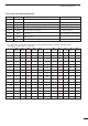
6 SPECIFICATIONS AND OPTIONS ■ Specifications Specifications are measured in accordance with EN 300 086. D IC-FR3100 General • Frequency coverage • Channel spacing : 150.000–174.000 MHz : 12.5/25.0 kHz (Narrow/Wide) 12.5/20.0 kHz (Narrow/Middle) • PLL channel step : 5.0, 6.25 kHz • Frequency stability : ±1.0 kHz • Number of channels : Max. 32 channel • Antenna connector : Type-N × 2 (50 Ω) • Operating temp. range : –25°C to +55°C • Power supply voltage : 220–240 V AC (50/60 Hz) 13.
SPECIFICATIONS AND OPTIONS Transmitter • RF output power • Modulation system • Max. frequency deviation • Spurious emissions • Adjacent channel power • Intermodulation attenuation • Audio harmonic distortion • Microphone impedance : 25 W : Variable reactance frequency modulation system : ±5.0 kHz (Wide), ±4.0 kHz (Middle), ±2.5 kHz (Narrow) : Less than 0.25 µW (≤1 GHz) Less than 1 µW (>1 GHz) : More than 70 dB (Wide, Middle), More than 60 dB (Narrow) : More than 40 dB : 3.
8 ABOUT CE INSTALLATION NOTES • Compliance of base station transmitter installations with EN50385 The installation of this equipment and it’s associated antenna should be made in such a manner as to respect the EC recommended electromagnetic (EM) field exposure limits.
ABOUT CE • Typical installation example A UHF base station transmitter is to be installed on the roof of an office. The transmit power is 25 watts, there is 20 m of RG213 coaxial cable and the antenna is vertically polarised dipole. The specification of the RG-213 cable gives a loss of 1.5 dB/10 m. There will be 3 dB loss for the 20 m length used. The RF power at the antenna input will be 12.5 watts. The dipole antenna has a forward gain of 0 dBd or 1.6, giving an EIRP of 20 watts.
8 ABOUT CE Network Compatibility Notice Icom IC-FR3100/IC-FR4100 PSTN Interface Scope This Network Compatibility Notice contains national requirements for proper operation of telecommunications equipment within specific countries and is based on the ETSI document “A guide to the application of TBR21,” 0168 . EG201 121 V1.1.3 (02-2002).
ABOUT CE 8 DECLARATION OF CONFORMITY We Icom Inc. Japan 0168 1-1-32, Kamiminami, Hirano-ku Osaka 547-0003, Japan Declare on our sole responsibility that this equipment complies with the essential requirements of the Radio and Telecommunications Terminal Equipment Directive, 1999/5/EC, and that any applicable Essential Test Suite measurements have been performed.
■ GER ■ FRA ■ ESP ■ ■ AUT ■ NED ■ POR ■ ■ GBR ■ BEL ■ ITA ■ ■ IRL ■ LUX ■ GRE ■ ■ NOR A-6280H-1EU-w Printed in Japan © 2003—2006 Icom Inc.