
Operation Manual


1
PANEL DESCRIPTION
1
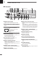
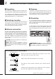
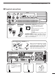
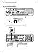
■ Front panel
q POWER SWITCH [POWER]
Toggle to turn the repeater power ON or OFF.
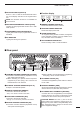
w
MICROPHONE/SPEAKER CONNECTOR [MIC/SP]
This 8-pin modular jack accepts the optional micro-
phone.
q +9 V DC output (Max. 10 mA)
w I/O port for PC programming
e NC
r M PTT (Input port for TX control)
t Microphone ground
y Microphone input
u Ground
i M MONI (Input port for monitor control)
e LINE CONNECTOR [LINE]
This 4-pin modular jack allows connection of a 2
wire system telephone cable.
• See p. 7 for line connector information.
r VOLUME CONTROL [VOLUME] (p. 12)
Adjusts the audio output level.
t SQUELCH CONTROL [SQUELCH]
➥While in base operating mode, adjusts the
squelch threshold level. (p. 12)
➥While in repeater operating mode, this knob is not
activated.
y CHANNEL SELECT SWITCHES [DN/UP]
Push either switch to select the operating channel.
u MONITOR SWITCH [MONI]
➥Push to monitor the operating frequency.
i MODE SELECT SWITCH [RPT/BASE]
Toggles the repeater or base operating mode when
pushed.
• When setting up a repeater system using IC-
FR3100/FR4100 only, select a repeater operating mode.
• When using IC-FR3100/FR4100 as a full (or half) duplex
transceiver, or setting up a repeater system connecting
an external controller, select a base operating mode.
o REMOTE CONTROL SWITCH [REMOTE]
Toggle to activate or inactivate the remote control
operation when pushed.
!0 AF MUTE CONTROL [SP MUTE]
Mutes the audio output.
!1 INTERNAL SPEAKER
Monitors received signals.
!2 BASE OPERATING MODE INDICATOR
Lights green while in base operating mode.
!3 REMOTE CONTROL MODE INDICATOR
Lights green while in remote control operation
mode.
!4 TRANSMIT INDICATOR
Lights red while transmitting.
!5 BUSY INDICATOR
Lights green while receiving a signal or when the
noise squelch is open.
q
i
q
w
e t y u i o !0
!2 !1!3!4!5!6!7
!8!9
r
Function display (p. 2)