
Operation Manual


4
1
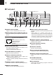
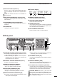
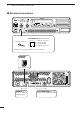
PANEL DESCRIPTION
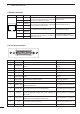
Channel
D4 D3 D2 D1 D0
(pin 18) (pin 5) (pin 17) (pin 4) (pin16)
100000
200001
300010
400011
500100
600101
700110
800111
901000
10 0 1 0 0 1
11 0 1 0 1 0
12 0 1 0 1 1
13 0 1 1 0 0
14 0 1 1 0 1
15 0 1 1 1 0
16 0 1 1 1 1
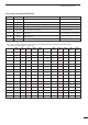
Channel
D4 D3 D2 D1 D0
(pin 18) (pin 5) (pin 17) (pin 4) (pin16)
17 1 0 0 0 0
18 1 0 0 0 1
19 1 0 0 1 0
20 1 0 0 1 1
21 1 0 1 0 0
22 1 0 1 0 1
23 1 0 1 1 0
24 1 0 1 1 1
25 1 1 0 0 0
26 1 1 0 0 1
27 1 1 0 1 0
28 1 1 0 1 1
29 1 1 1 0 0
30 1 1 1 0 1
31 1 1 1 1 0
32 1 1 1 1 1
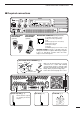
Accessory connector (continued)
Pin No. Pin Name Description Specification
15
16
17
18
19
20
21–24
25
M/S OUT
D0
D2
D4
EXT PTT
RSSI
AGND
DC GND
Output terminal for master/slave signal.
Input terminal for selecting memory channel.
Input terminal for selecting memory channel.
Input terminal for selecting memory channel.
Input terminal for PTT signal.
Output terminal for RSSI (Received Signal Strength Indica-
tor) signal.
Analog ground
Ground for +15 V DC
Open collector=OFF, 0V=ON
+5 V pull up, Active=L
+5 V pull up, Active=L
+5 V pull up, Active=L
+5 V pull up, Active=L
Output impedance: 1 kΩ (approx.)
• Pin 4, pin 5, pins 16–18 select one of the 32 pre-programmed memory channels. (see table below)
[0]: Hi-Z, [1]: 0 V (D0–D4: +5 V pull up)