INSTRUCTION MANUAL VHF MARINE TRANSCEIVER iM23
DOC CE versions of the IC-M23 which display the “CE” symbol on the serial number label, comply with the essential requirements of the European Radio and Telecommunication Terminal Directive 1999/5/EC. This warning symbol indicates that this equipment operates in non-harmonised frequency bands and/or may be subject to licensing conditions in the country of use.
IN CASE OF EMERGENCY RECOMMENDATION If your vessel requires assistance, contact other vessels and the Coast Guard by sending a distress call on Channel 16. CLEAN THE TRANSCEIVER THOROUGHLY WITH FRESH WATER after exposure to saltwater, and dry it before operating. Otherwise, the transceiver's keys, switches and controllers may become unusable due to salt crystallization. ❍ USING CHANNEL 16 DISTRESS CALL PROCEDURE 1. “MAYDAY MAYDAY MAYDAY.” 2.
FOREWORD FEATURES Thank you for purchasing this Icom radio. The IC-M23 VHF MARINE TRANSCEIVER is designed and built with Icom’s state of the art technology and craftsmanship. With proper care this radio should provide you with years of trouble-free operation. ☞ Floats on water • When a third-party battery pack, strap, antenna, etc. is used, it may sink. IMPORTANT READ ALL INSTRUCTIONS carefully and com- pletely before using the transceiver.
PRECAUTIONS RWARNING! NEVER connect the transceiver to an AC outlet. This may pose a fire hazard or result in an electric shock. RWARNING! NEVER hold the transceiver so that the antenna is closer than 2.5 cm from exposed parts of the body, especially the face or eyes, while transmitting. The transceiver will perform best if the microphone is 5 to 10 cm away from the lips and the transceiver is vertical. CAUTION: NEVER connect the transceiver to a power source other than the BC-199 or BP-266.
TABLE OF CONTENTS DOC................................................................................................... i IN CASE OF EMERGENCY ............................................................. ii RECOMMENDATION ....................................................................... ii FOREWORD ................................................................................... iii IMPORTANT ....................................................................................
OPERATING RULES D Priorities • Read all rules and regulations pertaining to call priorities, and keep an up-to-date copy handy. Safety and distress calls take priority over all others. • You must monitor Channel 16 when you are not operating on another channel. 1 (2) OPERATOR’S LICENSE A Restricted Radiotelephone Operator Permit is the license most often held by small vessel radio operators when a radio is not required for safety purposes.
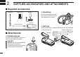
2 SUPPLIED ACCESSORIES AND ATTACHMENTS ■ Supplied accessories Handstrap Battery pack Charger* D Handstrap Pass the handstrap through the loop on the back side of the transceiver as shown. Belt clip Flexible antenna D Belt clip *Not supplied or different types are supplied, depending on the version. Attach the belt clip to, or detach the belt clip from the transceiver. To attach the belt clip ■ Attachments D Flexible antenna Connect the supplied flexible antenna to the antenna connector.
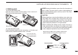
SUPPLIED ACCESSORIES AND ATTACHMENTS D Battery pack To remove the battery pack: Slide the latch and then lift the battery cover to remove it. Then remove the battery pack, as shown. Latch Battery pack Battery cover To insert the battery pack: Place the battery pack into the transceiver so it fits flat, and then securely attach the battery cover, as shown. NEVER remove the battery cover when the transceiver is wet or soiled.
3 PANEL DESCRIPTION ■ Front, top and side panels q ANTENNA CONNECTOR (p. 2) Connect the supplied antenna here. q w DC JACK [DC] (p. 23) Connect the charger or optional cable here. w q To remove the [DC] jack cap, rotate it counter clockwise. e Speaker Microphone Function display (pp. 6, 7) w Pull the cap up to detach it. u i r t y 4 o !0 !1 NOTE: Attach the [DC] jack cap when the charger or optional cable is not connected. Otherwise, water will get into the transceiver.
PANEL DESCRIPTION t VOLUME/SQUELCH/MONITOR KEY [VOL/SQL MONI] ➥ Push to enter the volume adjustment mode or the squelch adjustment mode. (p. 10) Normal operating mode PUSH Volume adjustment mode PUSH Squelch adjustment mode PUSH ➥ Hold down for 1 second to activate the Monitor function. (p. 13) ➥ While holding down this key, hold down [ ] to turn ON the power and enter the Set mode. (p. 17) ➥ While in the Set mode, push to select an item. (p.
3 PANEL DESCRIPTION ■ Function display q w e r t t CHARGE ICON (p. 23) Appears while charging. y u !7 o !6 !5 i !0 y BATTERY ICONS ➥ Displays the remaining battery capacity. Indication Charging Exhausted required !1 Battery status !2 !3 blinks when the battery is over charged. ➥ Scrolls while charging. (p. 23) Full Middle !4 q TRANSMIT ICON (p. 11) Appears while transmitting. w BUSY ICON ➥ Appears while receiving a signal or when the squelch opens. (p. 11) ➥ Blinks while monitoring. (p.
PANEL DESCRIPTION !1 SUB CHANNEL READOUT ➥ Displays Channel 16 during a priority scan, Dualwatch or Tri-watch. (p. 16) ➥ Displays the Set mode item while in the Set mode. (p. 17) ➥ Displays the volume level while in the volume adjustment mode. (p. 10) ➥ Displays the squelch level while in the squelch adjustment mode. (p. 10) !2 SQUELCH LEVEL ICON ➥ Displays the squelch level. ➥ “SQL” blinks while adjusting the squelch level. (p. 10) !3 VOLUME LEVEL ICON ➥ Displays the volume level.
4 BASIC OPERATION ■ Channel selection IMPORTANT: Prior to using the transceiver for the first time, the battery pack must be fully charged for optimum life and operation (p. 23). To avoid damage to the transceiver, turn OFF the power while charging. D Channel 16 Channel 16 is the distress and safety channel. It is used for establishing initial contact with a station, and for emergency communications. Channel 16 is monitored during both Dualwatch and Tri-watch.
BASIC OPERATION D USA, International, Canadian and ATIS channels The transceiver is pre-programmed with USA* 1, International, Canadian*2 and ATIS*3 channels. Choose the appropriate channel groups for your operating area. For German and Holland versions Hold down q Push [CH] to select a regular channel. w Hold down [CH] for 1 second, one or more times, to select the desired channel group. • The selectable channel groups are different, depending on the version.
4 BASIC OPERATION ■ Adjusting the volume level ■ Adjusting the squelch level The volume level can be adjusted using [VOL/SQL] and [Y] or [Z]. The squelch level can be adjusted using [VOL/SQL] and [Y] or [Z]. In order to properly receive signals, as well as for the scan to effectively function, the squelch must be adjusted to the proper level. q Push [VOL/SQL] once to enter the volume adjustment mode, then push [Y] or [Z] to adjust the volume level. • The “VOL” icon starts blinking.
BASIC OPERATION 4 ■ Receiving and transmitting CAUTION: Transmitting without an antenna can damage the transceiver. q Hold down [ ] to turn ON the power. w Set the volume and squelch levels. You can enter each adjustment mode by pushing [VOL/ SQL]. ➥ Enter the squelch adjustment mode, and then push [Z] one or more times to open the squelch. ➥ Enter the volume adjustment mode, and then push [Y] or [Z] to adjust the volume level.
4 BASIC OPERATION ■ Call channel programming ■ Volume Loud function Call channel is used to access Channel 16 (default; may differ depending on the version). However, you can program the Call channel with your most often-used channel in each channel group, for quick recall. The Volume Loud function temporarily maximizes the volume level. This function has no effect when the volume level is 31. q Hold down [CH] for 1 second, one or more times, to select the desired channel group to be programmed. (p.
BASIC OPERATION 4 ■ Lock function ■ Automatic backlighting This function electronically locks all keys (except for [PTT], [VOL/ ] (Hi/Lo) and [Y] or [Z]*) to preSQL], [MONI] (VOL/SQL), [ vent accidental changing of the channel and function access. This function lights the function display and keys, and is convenient for night-time operation. The automatic backlighting can be activated in the Set mode. (p. 19) ➥ Push any key except for [PTT] to turn ON the backlight.
5 SCAN OPERATION (Except Holland version) ■ Scan types Scanning is an efficient way to quickly locate signals over a wide frequency range. The transceiver has a priority scan and a normal scan. Set the TAG channels (scanned channels) before scanning. Clear the TAG for unwanted channels which inconveniently stop scanning, such as those for digital communications. (p. 15) In addition, the Auto Scan function is selectable for standby convenience.
SCAN OPERATION 5 ■ Setting TAG channels ■ Starting a scan For more efficient scanning, add the desired channels as TAG channels, or clear the TAG on unwanted channels. Channels that are not tagged will be skipped while scan. TAG channels can be independently assigned to each USA, International, Canada and ATIS channel group. Set the Priority Scan function, Scan Resume Timer and Auto Scan function in advance, in the Set mode. (p.
6 DUALWATCH/TRI-WATCH (Except Holland version) ■ Description ■ Operation Dualwatch monitors Channel 16 while you are receiving on another channel; Tri-watch monitors Channel 16 and the Call channel while receiving another channel. Dualwatch/Triwatch are convenient for monitoring Channel 16 when you are operating on another channel. q Select Dualwatch or Tri-watch in the Set mode. (p. 19) w Select the desired channel.
SET MODE 7 ■ Set mode programming The Set mode is used to change the settings of transceiver's functions: Beep Tone function, Priority Scan function*, Scan resume timer*, Auto Scan function*, Dual/Tri-watch function*, Monitor key action, Automatic backlighting, LCD contrast setting and Power Save function. D Set mode operation *Not available with Holland version. e Push [VOL/SQL] to select a desired item. Or while holding down [VOL/SQL], push [Y] or [Z] also selects an item.
7 SET MODE ■ Set mode items D Beep Tone function D Scan resume timer “St” (Not available with Holland version) “bP” Turn the key touch beep sound ON or OFF. The Scan resume timer can be set as a pause (OFF) or timer scan (ON). • OFF: When a signal is detected, the scan pauses on the channel until the signal disappears, and then resumes. • ON : When a signal is detected, the scan pauses on the channel for 5 seconds, and then resumes. • OFF: For silent operation. • ON : A beep sounds.
7 SET MODE D Dual/Tri-watch function “dt” (Not available with Holland version) Set the watch type to Dualwatch or Tri-watch. (p. 16) “bL” This function is convenient for night-time operation. The backlight can be selected from ON and OFF. • The backlight is automatically activated when any key except [PTT] is pushed. • The backlight is automatically turned OFF after 5 seconds of inactivity.
7 SET MODE D Power Save function “PS” The Power Save function reduces current drain by turning OFF the receiver circuit for preset intervals. • OFF : The Power Save function is turned OFF. • ON : The Power Save function is turned ON.
BATTERY CHARGING ■ Battery caution Misuse of Lithium-ion batteries may result in the following hazards: smoke, fire, or the battery may rupture. Misuse can also cause damage to the battery or degradation of battery performance. R DANGER! Use and charge only specified Icom battery pack with Icom radios or Icom chargers. Only Icom battery packs are tested and approved for use and charge with Icom radios or Icom chargers.
8 BATTERY CHARGING ■ Battery caution (continued) CAUTION: Shorter battery life could occur if the battery is left fully charged, completely discharged, or in an excessive temperature environment (above +50˚C) for an extended period of time. If the battery must be left unused for a long time, it must be detached from the radio after discharging.
BATTERY CHARGING ■ Supplied battery charger D Charging Do not use a charger other than the specified one. q Turn OFF the transceiver's power. w Connect the charger as shown below. •“ ” appears, and the battery icon scrolls while charging. e The charging is completed in approximately 8.5 hours, depending on the remaining capacity before charging. •“ ” and “ ” appear, and “FL” is also displayed on the function display when charging is completed.
8 BATTERY CHARGING D AD-123 installation (continued) w Install the AD-123 into the holder space of the BC-119N or BC-121N with the supplied screws as shown. Screws supplied with the charger adapter D Charging • For BC-119N The optional BC-119N provides rapid charging of the Li-ion battery pack. (Charging time: Approximately 2.
BATTERY CHARGING 8 D Charging from a cigarette lighter socket • For BC-121N The optional BC-121N allows up to six battery packs to be charged simultaneously. Use the optional CP-24 CIGARETTE from a cigarette lighter socket. LIGHTER CABLE charge Charging time: Approximately 8.5 hours. Charging time: Approximately 2.5 hours [DC] jack The following items are additionally required.
9 TROUBLESHOOTING PROBLEM POSSIBLE CAUSE SOLUTION The transceiver does not turn • The battery is exhausted. • Recharge the battery pack. ON. • The battery pack is not correctly in- • Correctly insert the battery pack. serted. No sound from speaker. • The squelch level is too high. • Volume level is too low. • Speaker has been exposed to water. 26 p. 23 p. 3 • Set the squelch level to the threshold level. p. 10 • Adjust the audio level to a suitable level. p. 10 • Remove water from the speaker grill.
VHF MARINE CHANNEL LIST Channel number USA*3 INT CAN 01 01 01A 02 02 03 03 03A 04 04A 05 05A 05A 06 06 06 07 07A 07A 08 08 08 09 09 09 10 10 10 11 11 11 12 12 12 13*1 13 13*1 14 14 14 15*1 15*1 15*1 16 16 16 17*1 17 17*1 18 18A 18A 19 19A 19A 20 20*1 20 20A Frequency (MHz) Transmit Receive 156.050 160.650 156.050 156.050 156.100 160.700 156.150 160.750 156.150 156.150 156.200 160.800 156.200 156.200 156.250 160.850 156.250 156.250 156.300 156.300 156.350 160.950 156.350 156.350 156.400 156.400 156.450 156.
11 SPECIFICATIONS AND OPTIONS ■ Specifications D GENERAL • Frequency coverage : Transmitting 156.000–161.450 MHz Receiving 156.000–163.425 MHz • Mode : FM (16K0G3E) • Antenna impedance : 50 Ω (nominal) • Power supply requirement : BP-266 only • Current drain (approximately) : TX (5 W/1.0 W/0.5 W) 2.3 A/0.9 A/0.7 A Maximum audio 0.35 A typical Power save 8 mA typical • Frequency stability : ±1.5 kHz • Operating temperature range : –15°C to +55°C • Dimensions : 58.5 (W) × 128.5(H) × 34.
SPECIFICATIONS AND OPTIONS 11 ■ Options D BATTERY PACK • BP-266 Li-ion BATTERY PACK Voltage/Capacity : 3.7 V/1500 mAh (minimum), 1590 mAh (typical) D CHARGERS • BC-199S AC ADAPTER For regular charging of the battery pack. Charging time : Approximately 8.5 hours • BC-119N DESKTOP CHARGER + AD-123 CHARGER ADAPTER + BC-145S AC ADAPTER For rapid charging of the battery pack. The AC adapter, BC-145S, is not supplied with some versions. Charging time : Approximately 2.
< Intended Country of Use > AT FI IT PL GB RO BE FR LV PT IS TR CY DE LT SK LI HR CZ GR LU SI NO DK HU MT ES CH EE IE NL SE BG A-6925H-1EX Printed in Japan © 2011 Icom Inc. Printed on recycled paper with soy ink.