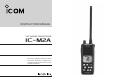
INSTRUCTION MANUAL VHF MARINE TRANSCEIVER iM2A This device complies with Part 15 of the FCC Rules. Operation is subject to the condition that this device does not cause harmful interference.
FOREWORD FEATURES Thank you for purchasing this Icom product. The IC-M2A VHF MARINE TRANSCEIVER is designed and built with Icom’s superior technology and craftsmanship. With proper care this product should provide you with years of trouble-free operation. carefully and com- pletely before using the transceiver. SAVE THIS INSTRUCTION MANUAL—This instruction manual contains important operating instructions for the IC-M2A.
CAUTIONS RWARNING! NEVER connect the transceiver to an AC outlet. This may pose a fire hazard or result in an electric shock. BE CAREFUL! The transceiver rear panel will become hot when operating continuously for long periods. BE CAREFUL! antenna is very close to, or touching exposed parts of the body, especially the face or eyes, while transmitting. The transceiver will perform best if the microphone is 5 to 10 cm away from the lips and the transceiver is vertical.
SAFTY TRAINING INFORMATION Your Icom radio generates RF electromagnetic energy during transmit mode. This radio is designed for and classified as “Occupational Use Only”, meaning it must be used only during the course of employment by individuals aware of W ARN ING the hazards, and the ways to minimize such hazards. This radio is NOT intended for use by the “General Population” in an uncontrolled environment.
IN CASE OF EMERGENCY • ALWAYS keep the antenna at least 2.5 cm (1 inch) away from the body when transmitting and only use the Icom belt-clips which listed in page 25 when attaching the radio to your belt, etc., to ensure FCC RF exposure compliance requirements are not exceeded. To provide the recipients of your transmission the best sound quality, hold the antenna at least 5 cm (2 inches) from mouth, and slightly off to one side.
TABLE OF CONTENTS FOREWORD ....................................................................... ii IMPORTANT ........................................................................ ii EXPLICIT DEFINITIONS ..................................................... ii FEATURES .......................................................................... ii CAUTIONS ......................................................................... iii SAFTY TRAINING INFORMATION ....................................
OPERATING RULES D Priorities • Read all rules and regulations pertaining to priorities and keep an up-to-date copy handy. Safety and distress calls take priority over all others. • You must monitor channel 16 when you are not operating on another channel. 1 (2) OPERATOR’S LICENSE A restricted Radiotelephone Operator Permit is the license most often held by small vessel radio operators when a radio is not required for safety purposes.
2 PANEL DESCRIPTION ■ Front panel r SCAN/TAG SWITCH [SCAN • TAG] • Starts and stops normal or priority scan when tag channels are programmed. • Sets and clears the displayed channel as a tag (scanned) channel when pushed for 1 sec. • While pushing this switch, turn the power ON to clears all tag channels in the selected regular channel group. q CHANNEL/WEATHER CHANNEL SWITCH [CH/WX•U/I/C] • Selects and toggles the regular channels and weather channel when pushed momentarily.
PANEL DESCRIPTION 2 ■ Top and side panels q ANTENNA CONNECTOR Connects the supplied antenna. w q w VOLUME CONTROL [OFF/VOL] Turns power ON and adjusts the audio level. e PTT SWITCH [PTT] Push and hold to transmit; release to receive. ï BATTERY CASE RELEASE BUTTON To remove the battery case: Turn the screw counterclockwise, then pull the battery pack in the direction of the arrow as shown below. To attach the battery case: Insert the battery case in the IC-M2A completely, then turn the screw clockwise.
2 PANEL DESCRIPTION ■ Function display q TRANSMIT INDICATOR Appears while transmitting. (p. 8) w BUSY INDICATOR Appears when receiving a signal or when the squelch level is set to the “OFF” position. (p. 8) q w e r e TAG CHANNEL INDICATOR Appears when a tag channel is selected. t y u u !7 !6 o !5 !0 !4 !1 !3 !2 r SCAN INDICATOR Blinks while scanning. t CALL CHANNEL INDICATOR Appears when the call channel is selected. (p. 9) y LOCK INDICATOR Appears while the lock function activated.
PANEL DESCRIPTION i DUPLEX INDICATOR Appears when a duplex channel is selected. o DUALWATCH/TRI-WATCH INDICATORS “DUAL” appears during dualwatch; “TRI” appears during tri-watch. (p. 10) !0 SUB CHANNEL READOUT • Indicates channel 16 during priority scan. (p. 11) • Indicates channel 16 during dualwatch or tri-watch. (p 10). Indication Full Middle !4 CHANNEL NUMBER READOUT • Indicates the selected operating channel number. (pgs. 6–8) • In SET mode, indicates the selected condition. (pgs.
3 BASIC OPERATION ■ Channel selection D Channel 16 Channel 16 is the distress channel. It is used for establishing initial contact with another station and for emergency communications. Channel 16 is monitored during dualwatch/tri-watch. While standing by you are required to monitor channel 16. Push 9 16 D U.S.A., Canadian and international channels There are 61 U.S.A., 57 Canadian and 57 international channels. These channel groups may be specified for the operating area.
BASIC OPERATION D Weather channels There are 10 weather channels. These are used for monitoring weather channels from the NOAA (National Oceanographic and Atmospheric Administration) broadcasts. The IC-M2A can detect a weather alert tone on a selected weather channel while scanning. See the “SET mode items” on p. 13. 3 ■ Adjusting the squelch level The IC-M2A has a squelch even though there is no control knob for it.
3 BASIC OPERATION ■ Receiving and transmitting CAUTION: Transmitting without an antenna may damage the transceiver. q Rotate [OFF/VOL] clockwise to turn power ON. - Use the squelch function to mute any audio noise if necessary. Refer to the previous page for details. w Push* [SQL.MONI] for 1 sec., and rotate volume to set audio output level. IMPORTANT: To maximize the readability of your transmitted signal, pause a few sec.
BASIC OPERATION 3 ■ Call channel programming The call channel switch is used to select channel 9 by default, however, you can program your most often-used channels in each channel group for quick recall. q Push [CH/WX • U/I/C] for 1 sec. several times to select the desired channel group (USA, INT, CAN) to be programmed. r Push [ ]/[ ] to select the desired channel. t Push [16 • 9] to program the displayed channel as the call channel. - The call channel number and channel group stop flashing.
4 DUALWATCH/TRI-WATCH ■ Description ■ Operation Dualwatch monitors channel 16 while you are receiving another channel; tri-watch monitors channel 16 and the call channel while receiving another channel. q Select the desired operating channel. w Push [DW • TRI] momentarily to start dualwatch; push [DW • TRI] for 1 sec. to start tri-watch. DUALWATCH/TRIWATCH SIMULATION Call channel - “DUAL” flashes during dualwatch; “TRI” flashes during tri-watch.
SCAN OPERATION 5 ■ Scan types Scanning is an efficient way to locate signals quickly over a wide frequency range. The transceiver has a priority scan and a normal scan. Set the tag channels (channels to be scanned) before scanning. Clear the tag channels which inconveniently stop scanning, such as those used for digital communications. In addition, weather alert functions is available for standby convenience. (p. 13) NOTE: Choose priority or normal scan in SET mode. (P.
5 SCAN OPERATION ■ Setting tag channels ■ Starting a scan For more efficient scanning, add desired channels as tag channels or clear tag channels for unwanted channels. Channels set as non-tag channels will be skipped during scanning. Tag channels can be assigned to each channel group (USA, CAN, INT) independently. Set scan type, weather alert function and scan resume timer in advance using SET mode. (pgs. 13, 14) q Select the desired channel group (USA, CAN, INT) by pushing [CH/WX • U/I/C] for 1 sec.
SET MODE 6 ■ SET mode programming ■ SET mode items SET mode is used to change the conditions of 6 transceiver functions: the beep tone function, the automatic backlighting, weather alert function, normal/priority scan, scan resume timer and power save function. D Beep tone “bP” You can select silent operation by turning beep tones OFF or you can have confirmation beeps sound at the push of a switch by turning beep tones ON. The beep tone volume is linked with [OFF/VOL]. q Turn power OFF.
6 SET MODE D Scan type selection “Pr” D Auto scan function “AS” The transceiver has 2 scan types: normal scan and priority scan. Normal scan searches all tag channels in the selected channel group. Priority scan searches all tag channels in sequence while monitoring channel 16. While in standby, this function automatically starts the desired scan (normal or priority scan) 30 sec. after operation. • The comment indicator indicates “SCAN” while scanning.
SET MODE D Automatic backlighting “bL” This function is convenient for nighttime operation. THe automatic backlighting turns the backlighting ON when pushing any key except fpr [PTT]. 6 D Auto power save function “PS” The power save function reduces current drain by deactivating the receiver circuit for preset intervals. • The backlighting is automatically turned OFF after 5 sec. of inactivity.
6 SET MODE D Battery voltage indicator “bt” SET MODE LIST This function switches display or non-display voltage of connected battery pack when Power is ON. Function Indication Switch • The voltage of connected battery pack is displayed for 2 sec. since Power is ON.
BATTERY CHARGING ■ Installing batteries in the battery case When using a battery case attached to the transceiver, install 6 AA(R6) size alkaline batteries as illustrated below. q Remove the battery case from the transceiver. w Install 6 × AA(R6) size alkaline batteries. • Be sure to observe the correct polarity. CAUTION: • When installing batteries, make sure they are all the same brand, type and capacity. Also, do not mix new and old batteries together. • Keep battery contacts clean.
7 BATTERY CHARGING ï BC-150 installations ï Charging connections • To a desktop q Connect the AC adapter (BC-147A) as shown below. w Insert the battery pack with/without the transceiver into the charger. • The charge indicator light shows green. e Charge the battery pack approx. 8 hours, depending on the remaining power condition. Supplied screws CAUTION: DO NOT charge BP-224 more than 12 Charge indicator hours. Otherwise, BP-224 will be damaged. BP-224 must be charged while 8–12 hours.
BATTERY CHARGING 7 ■ Battery cautions NEVER incinerate used Ni-Cd batteries. Internal battery gas may cause an explosion. NEVER immerse batteries in water. If the battery case becomes wet, be sure to wipe it dry BEFORE attaching it to the transceiver. NEVER short terminals of the battery case. Also, current may flow into nearby metal objects so be careful when placing battery cases in handbags, etc.
8 SUPPLIED ACCESSORIES AND ATTACHMENT D Supplied accessories The following accessories are supplied: Qty. q Flexible antenna . . . . . . . . . . . . . . . . . . . . . . . . . . . . .1 w Belt clip . . . . . . . . . . . . . . . . . . . . . . . . . . . . . . . . . . . .1 e Rotary belt clip . . . . . . . . . . . . . . . . . . . . . . . . . . . . . . .1 r Handstrap . . . . . . . . . . . . . . . . . . . . . . . . . . . . . . . . . .1 t Battery case (BP-223)* . . . . . . . . . . . . . . . . . . . . . . . .
SUPPLIED ACCSSORIES AND ATTACHMENTS D Rotary belt clip To attach: q Slide the stopper into the plastic loop on the back of the transceiver. 8 e Bottom up the transceiver, and then insert the stopper to the back of belt clip. w Clip the belt clip to a part of belt. r Turn the transceiver in the direction of the arrow as below.
8 SUPPLIED ACCESSORIES AND ATTACHMENTS To remove: q Turn the transceiver to bottom up the transceiver. w Pull up the transceiver, and then take out the belt clip. 22 e Push the top of the stopper towards the transceiver and out at the same time, then push it downwards and free of the plastic loop.
9 TROUBLESHOOTING PROBLEM POSSIBLE CAUSE SOLUTION REF. No power comes ON. • The battery is exhausted. • Bad connection to the battery pack. • Recharge the battery pack. • Check the conection to the transceiver. p. 18 p. 3 No sound comes from the speaker. • Squelch level is too deep. • Volume level is too low. • Speaker has been exposed to water. • Set squelch to the threshold point. • Set [OFF/VOL] to a suitable level. • Drain water from the speaker. p. 7 p.
10 CHANNEL LIST Channel number Frequency (MHz) Channel number Frequency (MHz) Channel number Frequency (MHz) Channel number Frequency (MHz) USA INT CAN Transmit Receive USA INT CAN Transmit Receive USA INT CAN Transmit Receive USA INT CAN Transmit Receive 01 01 01A 156.050 160.650 156.050 156.050 02 02 02A 156.100 160.700 Guard 03 03 03A Guard 05 06 06 21A 65A 157.000 157.000 66A 66A 66A† 156.325 156.325 157.050 161.650 67† 67 67 156.375 156.375 85 21A 157.050 157.
SPECIFICATIONS AND OPTIONS ■ Specifications • GENERAL Frequency coverage Mode Channel spacing Current drain (at 7.2 V) Frequency stability Useable temperature range Dimensions (Projections not included) Weight • TRANSMITTER Output power (at 7.5 V) Modulation system : Transmit 156.025–157.425 MHz Receive 156.025–163.275 MHz : FM (16K0G3E) : 25 kHz : TX High (5 W) 1.5A typical. Max.
Count on us! A-6113-1US Printed in Japan © 2001 Icom Inc.