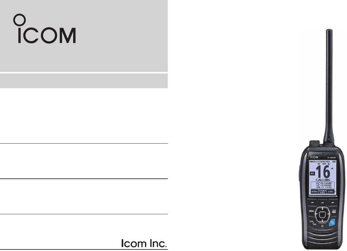
INSTRUCTION MANUAL VHF MARINE TRANSCEIVER iM93D iM93D EURO This device complies with Part 15 of the FCC Rules. Operation is subject to the condition that this device does not cause harmful interference.
FEATURES Thank you for choosing this Icom product. This product is designed and built with Icom’ s state of the art technology and craftsmanship. With proper care, this product should provide you with years of trouble-free operation. zzFloats on water IMPORTANT zzFloats and flashes READ ALL INSTRUCTIONS carefully and completely before using the transceiver. SAVE THIS INSTRUCTION MANUAL—This instruction manual contains important operating instructions for the IC-M93D and IC-M93D EURO.
IN CASE OF EMERGENCY If your vessel requires assistance, contact other vessels and the Coast Guard by sending a distress call on Channel 16. Or, transmit your Distress call using Digital Selective Calling (DSC) on Channel 70. USING CHANNEL 16 DISTRESS CALL PROCEDURE USING DIGITAL SELECTIVE CALLING (Ch 70) DISTRESS CALL PROCEDURE 1. “MAYDAY MAYDAY MAYDAY.” 2. “THIS IS ...............” (name of vessel). 3. Say your call sign or other indication of the vessel (AND your 9 digit DSC ID, if you have one).
PRECAUTIONS RRDANGER! NEVER short the terminals of the battery pack. Shorting may occur if the terminals touch metal objects such as a key, so be careful when placing the battery packs (or the transceiver) in bags, and so on. Carry them so that shorting cannot occur with metal objects. Shorting may damage not only the battery pack, but also the transceiver. RRDANGER! NEVER operate the transceiver near unshielded electrical blasting caps or in an explosive atmosphere.
RECOMMENDATION DO NOT push [PTT] unless you actually intend to transmit. BE CAREFUL! The IC-M93D and IC-M93D EURO meet IPX7* requirements for waterproof protection. However, once the transceiver has been dropped, waterproof protection cannot be guaranteed because of possible damage to the transceiver’s case or the waterproof seal. CLEAN THE TRANSCEIVER THOROUGHLY WITH FRESH WATER after exposure to saltwater, and dry it before operating.
INFORMATION FOR CLASS A UNINTENTIONAL RADIATORS This equipment has been tested and found to comply with the limits for a Class A digital device, pursuant to part 15 of the FCC Rules. These limits are designed to provide reasonable protection against harmful interference when the equipment is operated in a commercial environment.
TABLE OF CONTENTS IMPORTANT................................................................................................i FEATURES..................................................................................................i EXPLICIT DEFINITIONS.............................................................................i IN CASE OF EMERGENCY....................................................................... ii PRECAUTIONS..........................................................................
1 OPERATING RULES DDPriorities •• Read all rules and regulations pertaining to priorities and keep an up-to-date copy handy. Safety and distress calls take priority over all others. •• You must monitor Channel 16 when you are not operating on another channel. •• False or fraudulent distress calls are prohibited under law. DDPrivacy •• Information overheard but not intended for you cannot lawfully be used in any way. •• Indecent or profane language is prohibited.
SUPPLIED ACCESSORIES AND ATTACHMENTS ■■Supplied accessories Handstrap Battery pack Battery charger Power adapter* (with 2 screws) 2 DDBattery pack 1. Attach the battery pack to the transceiver. Battery pack Antenna Cigarette lighter cable* * May not be supplied, or different type may be supplied, depending on the transceiver version. ■■Attachments DDFlexible antenna onnect the supplied antenna to the antenna C connector. CAUTION: •• NEVER carry the transceiver by holding the antenna.
2 SUPPLIED ACCESSORIES AND ATTACHMENTS ■■ Attachments (Continued) DDHandstrap Pass the handstrap through the loop on the back side of the transceiver to make it easy to carry. DDBelt clip Attach or detach the belt clip to/from the transceiver as shown below. To attach the belt clip Belt clip To detach the belt clip Lift the tab up q and slide the belt clip in the direction of the arrow w. BE CAREFUL! Do not break your fingernail.
PANEL DESCRIPTION 3 ■■ Panel description !1 e UP/DOWN/LEFT/RIGHT KEYS [▲]/[▼]/[◄]/[►] zz Push [▲] or [▼] to select the operating channel, Menu items, Menu settings, and so on. zz Push [◄] or [►] to slide through the key functions that are assigned to the software keys. (p. 7) zz Push to select the desired character or number in the entry mode. (p. 9, 10, 15, 19, 21) !0 Microphone q r VOLUME/SQUELCH KEY [VOL/SQL] (p. 13) zz Push once to display the volume level setting screen.
3 PANEL DESCRIPTION ■■ Panel description (Continued) !1 ■■Display description !5 !0 o SOFTWARE KEYS Slide through the key functions by pushing [◄] or [►], and then push either of the 3 software keys to select the function displayed at the bottom of the display. See “Software keys” on page 7 for details. o !0 ANTENNA CONNECTOR (p. 2) Connects the supplied antenna. !1 SPEAKER MICROPHONE JACK (p. 63) Connects the optional external speaker microphone.
PANEL DESCRIPTION r STATUS ICON •• “STBY” is displayed while not receiving nor transmitting. •• “ RT” (Radio Telephone mode) is displayed while receiving or transmitting a signal or when the squelch opens. (p. 13, 56) ••“DSC” is displayed while in the DSC mode. t CHANNEL NAME ••The channel name is displayed, if entered. (p. 15) ••“SCAN” or “SCAN 16” is displayed while scanning. (p. 16) •• “DUAL 16” or “TRI 16” is displayed while using the Dualwatch or Tri-watch function. (p.
3 PANEL DESCRIPTION ■■Using the software keys ■■Software keys Various often-used functions are assigned to the software keys for easy access. The functions’ icons are displayed above the software keys, as shown below. ou can assign the following functions to the software keys Y on the Menu screen. DDSelecting a software key function 1. P ush [◄] or [►] to slide through the selectable functions that are assigned to the software keys. 2.
PANEL DESCRIPTION High/Low (p. 5) Push to set the power to high or low. (p. 11~12) Push to select regular channels or Weather* channels. L is displayed except for the USA, Australian, and Export versions. L While the Call channel or Channel 16 is displayed, push this key to return to the regular channel mode. * The Weather channels are for only the USA, Australian, and Export versions. AquaQuake (p. 15) Hold down to turn ON the AquaQuake function to clear water from the speaker grill.
4 PREPARATIONS ■■Entering the MMSI code The Maritime Mobile Service Identity (MMSI: DSC self ID) code consists of 9 digits. You can only enter the code when turning ON the transceiver for the first time. This initial code entry can be done only once. After entering, it can be changed only by your dealer or distributor. If your MMSI code has already been entered, this entry is not necessary. 1. Hold down [ ] to turn ON the transceiver.
PREPARATIONS 4 ■■Entering the ATIS ID (For Dutch and German versions) The Automatic Transmitter Identification System (ATIS) ID consists of 10 digits. You can enter the ID in the “ATIS ID Input” item on the Menu screen. This ID entering can be done only once. After entering, it can be changed only by your dealer or distributor. If your ATIS ID has already been entered, this entry is not necessary. 1. Push [MENU]. ••The Menu screen is displayed. 2.
5 BASIC OPERATIONS ■■Selecting a channel NOTE: Before using the transceiver for the first time, the battery pack must be fully charged for optimum life and operation. To avoid damage to the transceiver, turn OFF the transceiver before charging. DDChannel 16 Channel 16 is the distress and safety channel. It is used to establish the initial contact with a station and for emergency communications. Channel 16 is monitored during both Dualwatch and Tri-watch.
BASIC OPERATIONS DDSelecting a Channel Group Channel Groups are preset into your transceiver. You can select the Channel Group between USA, International, Canadian, DSC, and ATIS depending on the transceiver version. Version USA UK European Dutch German Australian Export (Other) USA Preset Channel Group INT CAN DSC 1. Push [MENU]. ••The Menu screen is displayed. 2. P ush [▲] or [▼] to select “Radio Settings,” and then push [ENT].
5 BASIC OPERATION ■■Adjusting the volume level ■■Setting the Call channel 1. Push [VOL/SQL]. By default, a Call channel is set in each Channel Group. You can set your most often-used channel as your Call channel in each Channel Group for a quick recall. •• The volume level adjustment screen is displayed. 2. P ush [◄] or [►] to adjust the volume level between 1 and 20, or OFF. L You can also push the software key below [MUTE] to select OFF, or below [LOUD] to set the maximum volume level.
BASIC OPERATION 5 ■■Receiving and transmitting CAUTION: Transmitting without an antenna may damage the transceiver. 1. Push [▲] or [▼] to select the channel to call. L You cannot transmit on Channel 70. L is displayed while receiving a signal. 2. Hold down [PTT] and speak into the microphone. •• is displayed while transmitting. 3. Release [PTT] to receive. Speak into the microphone Hold down to transmit. Release to receive. Select a channel.
5 BASIC OPERATION ■■Monitor function ■■Editing a channel name The Monitor function temporarily cancels the Squelch function to check for weak signals. You can edit the name of each operating channel and weather channel, using numbers, uppercase letters, symbols, and a space. This enables easy recognition of the channels or stations. All VHF marine channels are set with default names. 1. H old down [VOL/SQL] to turn ON the Monitor function. L The Monitor function is ON while [VOL/SQL] is held down.
SCAN (Exept for the Dutch version) 6 ■■Scan types You can find ongoing calls by scanning the Favorite channels. Before starting a scan, you need to: •• Set the channels that you want to scan as Favorite channels. (p. 17) Priority Scan The Priority Scan sequentially searches through all Favorite channels, while also monitoring Channel 16. LOnly the Favorite channels are scanned. CH 01 •• Set the scan type to “Priority Scan” or “Normal Scan” on the “Radio Settings” screen. (p.
6 SCAN (Except for the Dutch version) ■■Setting Favorite channels ■■Starting a scan You can quickly recall often-used channels by setting them as Favorite channels. You can set Favorite channels in each Channel Group. 1. Select a Channel Group. (p. 12) 2. Push [◄] or [►] to display . 3. Push the software key below . 1. Select a Channel Group. (p. 12) 2. Push [▲] or [▼] to select the channel you want to set as a Favorite channel. 3. Push [◄] or [►] to display . 4.
DUALWATCH/TRI-WATCH (Except for the Dutch version) ■■Description ■■Operation Dualwatch and Tri-watch are convenient to monitor Channel 16 while you are operating on another channel. 1. S elect Dualwatch or Tri-watch in “Radio Settings.” (p. 55) 2. Push [▲] or [▼] to select a channel. 3. Push [◄] or [►] to display (Dualwatch) or (Tri-watch). 4. Push the software key below the or .
8 DSC OPERATION ■■DSC address ID DDEntering an Individual ID You can enter a total of 75 Individual IDs, and assign names of up to 10 characters. 1. Display the “Individual ID” screen. [MENU] ► “DSC Settings” ► “Individual ID” ••“No ID” is displayed if no ID is entered. 2. P ush the software key below [ADD]. 4. P ush the software key below [NEXT] to start entering the name. TIP: •• Select [! $ ?] to use characters, and select [ABC] to use numbers and letters.
DSC OPERATION DDEntering a Group ID You can enter a total of 25 Group IDs, and assign names of up to 10 characters. 1. Display the “Group ID” screen. [MENU] ► “DSC Settings” ► “Group ID” 8 DDDeleting an Individual ID or Group ID [Example: Deleting an Individual ID: ICOM #2] 1. Display the “Individual ID” screen. [MENU] ► “DSC Settings” ► “Individual ID” 2. Push [▲] or [▼] to select “ICOM #2.” 3. Push [►] to display [DEL]. ••“No ID” is displayed if no ID is entered. 2.
8 DSC OPERATION ■■Entering the position and time A Distress call should include the vessel’s position and time. If no GPS data is received, manually enter the position and Universal Time Coordinated (UTC) time. NOTE: •• The manual entry is disabled while the GPS data is received. •• The manually entered position and time is valid only for 4 hours, or until turning OFF the transceiver. 1. Display the “Position Input” screen. [MENU] ► “DSC Settings” ► “Position Input” 2. Enter the latitude and longitude.
DSC OPERATION 8 ■■Sending DSC calls (Distress) A Distress call should be sent if, in the opinion of the Master, the ship or a person is in distress and requires immediate assistance. 4. Push any software key to turn OFF the alarm. •• Channel 16 is automatically selected. NEVER MAKE A DISTRESS CALL IF YOUR SHIP OR A PERSON IS NOT IN AN EMERGENCY. A DISTRESS CALL SHOULD BE MADE ONLY WHEN IMMEDIATE HELP IS NEEDED. DDSimple call 1. Confirm that no Distress call is being received. 2.
8 DSC OPERATION DDRegular call Select the nature of the Distress call to include in the Regular Distress call. 1. Push the software key below 4. After sending, wait for an Acknowledgement call. ••“Waiting for ACK” is displayed. . •• The “Distress Call” screen is displayed. 2. P ush [▲] or [▼] to select the nature of the call, and then push [ENT]. (Example: Flooding) ••The confirmation screen is displayed.
DSC OPERATION 8 DDDistress Cancel call NOTE (For USA and Export versions): After sending a Distress call without position data •• While waiting for an Acknowledgement, if valid position data is received, the transceiver will automatically send a Distress call again. •• Even after exiting the DSC mode, if valid position data is received within 20 minutes after receiving a Distress Acknowledgement, the transceiver will automatically send a Distress call again.
8 DSC OPERATION ■■Sending DSC calls (other) NOTE: To ensure proper DSC operation, be sure to correctly adjust the “CH 70 SQL Level” item on the Menu screen. (p. 44) DDSending an Individual call An Individual call enables you to send a DSC signal to only a specific station. You can communicate after receiving the Acknowledgement “Able to comply.” 1. Push [◄] or [►] to display . 2. Push the software key below 6. P ush the software key below [CALL] to send the Individual call.
DSC OPERATION Acknowledgement “Unable to comply” Push any software key to turn OFF the alarm. ••The Acknowledge information is displayed. L Push the software key below [EXIT] to return to the operating screen. 8 DDSending an Individual Acknowledgement When you have received an Individual call (p. 35), send an Acknowledgement to the calling station. When you send an Acknowledgement, select “Able to Comply,” “Propose New CH,” or “Unable to Comply.” 1.
8 DSC OPERATION DD Sending an Individual Acknowledgement (Continued) 4. S elect “Able to Comply,” “Unable to Comply,” or “Propose New CH.” • Able to Comply: Sends an Acknowledgement call without any changes. • Unable to Comply: Sends an Acknowledgement call but cannot communicate. • Propose New CH: Able to communicate but proposes another channel. Specify the channel by pushing [▲] or [▼]. (Example: Channel 77) 5. P ush the software key below [CALL] to send the Acknowledgement call.
DSC OPERATION DDSending a Group call A Group call enables you to send a DSC signal to only a specific group. L You can send a Group call to a pre-entered group address, or manually enter the address before sending. (p. 20) 1. Push [◄] or [►] to display . 2. Push the software key below 6. P ush the software key below [CALL] to send the Group call. •• “Transmitting Group Call” is displayed, and then the assigned channel is automatically selected.
8 DSC OPERATION DDSending an All Ships call Except for the USA and Export versions, you can send a call to all ships that carry DSC transceivers and to those that use Channel 70 as their listening channel in the range. . 1. Push [◄] or [►] to display 2. Push the software key below . 6. P ush the software key below [CALL] to send the All Ships call. •• “Transmitting All Ships Call” is displayed, and then the assigned channel is automatically selected.
DSC OPERATION DDSending a Test call You should avoid testing calls on the exclusive DSC distress channels and safety calling channels. When you cannot avoid testing on a distress or safety channel, you should indicate that these are test calls. Normally the test call would require no further communications between the two stations involved. 1. Push [◄] or [►] to display . 2. Push the software key below 5. Push the software key below [CALL] to send the Test call.
8 DSC OPERATION DDSending a Test Acknowledgement By default, when you receive a Test call, the Auto ACK function automatically sends an Acknowledgement to the calling station (p. 42). If the function is set to “Manual,” do the following steps to send an Acknowledgement. 4. P ush the software key below [CALL] to send the Acknowledgement. •• “Transmitting Test ACK” is displayed. 1. A fter a Test call is being received, push any software key to turn OFF the alarm. 2.
DSC OPERATION Sending on the “Compose Other” screen You can also send a Test Acknowledgement by selecting “Test ACK” on the “Compose Other” screen. This enables you to resend an Acknowledgement, or send even after ignoring the call when you first received it. 1. Push the software key below . ••The ”Compose Other” screen is displayed. 2. P ush [▲] or [▼] to select “Test ACK,” and then push [ENT]. ••The Test caller’s station or MMSI is displayed.
8 DSC OPERATION DD Sending a Position Reply call (Continued) 4. Select the reply “Able to Comply.” LSelect “Unable to Comply” if you cannot send a reply call. 5. Push the software key below [CALL] to send the reply. •• “Transmitting Position Reply” is displayed. ••After sending, the replied information is displayed. Sending on the “Compose Other” screen You can also send a Position Reply call by selecting “Position Reply” on the “Compose Other” screen.
DSC OPERATION ■■Receiving DSC calls (Distress) The transceiver receives Distress calls, Distress Acknowledgement calls, and Distress Cancel calls. L When you receive a call, an emergency alarm sounds. NOTE: The screens that are displayed when a Distress call or an Acknowledgement call is received slightly differ from one another. The following steps are described using an example of receiving a Distress call. When a Distress call is received: ••The emergency alarm sounds until you turn it OFF.
8 DSC OPERATION ■■Receiving DSC calls (other) The transceiver receives the following types of DSC calls. ••Individual call (p. 35) ••Individual Acknowledgement call (p. 25) ••Group call (p. 36) ••All Ships call (p. 37) ••Position Request call (p. 38) ••Test call (p. 39) ••Test Acknowledgement call (p. 40) DDReceiving an Individual call When an Individual call is received: ••The alarm sounds. ••“RCVD INDV Call” is displayed. 1. Push any software key to turn OFF the alarm. 2.
DSC OPERATION DDReceiving a Group call When a Group call is received: ••The alarm sounds for 2 minutes. ••“RCVD Group Call” is displayed. 1. Push any software key to turn OFF the alarm. L The channel that is assigned by the caller is automatically selected after 10 seconds by default. 2. Push the software key below your next operation. [PAUSE] L [PAUSE] is not displayed if the “CH Auto Switch” item is set to “Manual.” (p.
8 DSC OPERATION DDReceiving an All Ships call When an All Ships call is received: ••The alarm sounds. ••“RCVD All Ships Call” is displayed. 1. Push any software key to turn OFF the alarm. L The traffic channel that is assigned by the caller is automatically selected after 10 seconds by default. 2. Push the software key below your next operation. [PAUSE] L [PAUSE] is not displayed if the “CH Auto Switch” item is set to “Manual.” (p.
DSC OPERATION DDReceiving a Position Request call When a Position Request call is received: ••The alarm sounds for 2 minutes. ••“RCVD POS Request” is displayed. 1. P ush any software key to turn OFF the alarm. 2. Push the software key below the intended operation. [ABLE] ••Sends the Acknowledgement “Able to Comply.” •• The call is saved in the DSC Log. [UNABL] •• Sends the Acknowledgement “Unable to Comply.
8 DSC OPERATION DDReceiving a Test call TIP: By default, the Auto ACK function automatically sends an Acknowledgement to the calling station (p. 42). If the function is set to “Manual,” the following screens are displayed. When a Test call is received: ••The alarm sounds for 2 minutes. ••“RCVD Test Call” is displayed. 1. P ush any software key to turn OFF the alarm. 2. Push the software key below your next operation. [IGN] ••Ignores the call and returns to the operating screen.
DSC OPERATION 8 ■■DSC Log DDReceiving a Test Acknowledgement call After sending a Test call, the called station will send you a Test Acknowledgement call. When a Test Acknowledgement call is received: ••The alarm sounds for 2 minutes. ••“Received ACK” is displayed. Push any software key to turn OFF the alarm. •• The received call’s information is displayed. •• The call is saved in the DSC Log. L Push the software key below [EXIT] to return to the operating screen.
8 DSC OPERATION DD Received DSC log (Conitnued) 4. Push [▲] or [▼] to scroll through the log. 5. Push [ENT] to display the received call’s information. Received Distress log DDSent DSC Log The transceiver saves up to 50 DSC sent calls in your DSC Log. 1. Display the “DSC Log” screen. [MENU] ► “DSC Log” 2. P ush [▲] or [▼] to select “Transmitted,” and then push [ENT]. •• The “Transmitted” screen is displayed. 3. P ush [▲] or [▼] to scroll through the log. 4.
DSC OPERATION 8 ■■DSC Settings On the “DSC Settings” screen, you can make settings on the DSC call related items. Position Input See “Entering the position and time” on page 21 for details. Individual ID See “Entering an Individual ID” on page 19 for details. Group ID See “Entering a Group ID” on page 20 for details. Auto ACK The Auto ACK function automatically sends an Acknowledgement call when the following calls are received.
8 DSC OPERATION ■■ DSC Settings (Continued) Unread Return (Default: On) This function puts the received DSC call on hold while receiving another call. On: W hile receiving another call, the received DSC call is put on hold until the currently receiving call is hung up. Off: W hile receiving another call, the received DSC call is saved in the DSC Log.
DSC OPERATION CH 70 SQL Level (Default: 5) Adjust the Squelch level for Channel 70 to between 1 and 10, or Open. L“ ” is displayed when adjusted to Open. A higher level blocks weak signals, which enables you to send a DSC call. DST at PW Off (Default: Valid) 8 Loop Test This function sends DSC signals to the receiving AF circuit to compare the sending and receiving signals at the AF level. Push [ENT] to start the Loop Test. L When the sending and receiving DSC signals match, “OK” is displayed.
9 OTHER FUNCTIONS ■■MOB (Man OverBoard) You can enter a Man OverBoard (MOB) waypoint into the transceiver with its GPS position data, as soon as a person has fallen into the water and needs to be rescued. This enables you to reach the MOB position even in the dark, or when you have lost visual contact. DD Entering an MOB waypoint 1. P ush [◄] or [►] to display . 2. Hold down the software key below for 1 second to enter the MOB waypoint. •• After entering, “Man Overboard!” is displayed.
OTHER FUNCTIONS 9 ■■Waypoint Waypoints are GPS position data points of places you want to go to, the position of your own vessel, or of a vessel you received a DSC call from. You can enter up to 50 Waypoints with names of up to 10 characters. You can enter your current position information, or add one as a destination or landmarks you often go to, as information for easy access. DD Entering a Waypoint Entering your current position as a Waypoint: 1. P ush [◄] or [►] to display 2.
9 OTHER FUNCTIONS ■■ Waypoint (Continued) DD Entering a received position After receiving a Distress call that includes position data, you can enter the position as a Waypoint. This enables you to reach the caller’s position. 1. Push [◄] or [►] to display . 2. Push the software key below ••The “Received” screen is displayed. . 3. Push [▲] or [▼] to select “Distress.” 4. Select the received call and then push [ENT].
OTHER FUNCTIONS 9 ■■Navigation Adding a Waypoint: Push the software key below [ADD] to add a Waypoint. The Navigation function navigates from your current position to an entered regular Waypoint or MOB waypoint. L Add the Waypoint in the same manner that is described in “Manually entering a Waypoint” on page 46. Start navigating to the MOB waypoint: Editing a Waypoint: While selecting the Waypoint that you want to edit, push the software key below [EDIT] to edit the Waypoint. 1.
9 OTHER FUNCTIONS DD Navigation screen description ■■ Navigation (Continued) Start navigating to a Waypoint: L A Waypoint must be entered before navigating. 1. P ush [◄] or [►] to display . 2. Push the software key below •• The “Waypoint” screen is displayed. 3. P ush [▲] or [▼] to select a Waypoint. 4. After selecting, push the software key below [NAV] to start navigating to the Waypoint. . Range displays the radius of a compass circle. Push [▲] or [▼] to change the range between 0.
OTHER FUNCTIONS 9 ■■Compass ■■GPS/GNSS The Compass shows your vessel’s Course Over Ground (COG) and Speed Over Ground (SOG). The GPS or GNSS “Status” screen displays the quantity, signal power, and position of the GPS satellites in the sky view. The screen also displays the direction, elevation angle, satellite numbers, and their received signal strength. 1. Push [◄] or [►] to display . 2. Push the software key below ••The “Compass” screen is displayed. . Displays the display’s direction type.
9 OTHER FUNCTIONS DD GPS/GNSS Status screen (Continued) Sky view description: GPS mode* Your position ••Image of the satellite Satellite A Elevation angle 90 degree line (Zenith) Elevation angle 60 degree line Elevation angle 30 degree line Elevation angle 0 degree line Sky view * “2D” is displayed while tracking 3 or less satellites. “3D” is displayed while tracking more than 4 or more satellites.
OTHER FUNCTIONS ■■Information screen DD GPS/GNSS Information screen Information screen description: 1. Push [MENU]. ••The Menu screen is displayed. 2. P ush [▲] or [▼] to select “GPS,” and then push [ENT]. ••The “GPS” screen is displayed. L “GNSS” may be displayed, instead of “GPS,” depending on the transceiver version. 3. P ush [▲] or [▼] to select “Information” and then push [ENT]. You can check your transceiver’s software version, GPS module version, and ATIS ID* on the “Information” screen.
10 MENU SCREEN ■■Using the Menu screen The Menu screen is used to set items, select options, and so on for the transceiver’s functions. DD Using the Menu screen 3. P ush [▲] or [▼] to select “CHAN Group,” and then push [ENT]. •• The “CHAN Group” screen is displayed. Example: Setting the channel group to “INT.” 1. Push [MENU]. ••The Menu screen is displayed. 4. P ush [▲] or [▼] to select “INT,” and then push [ENT]. •• “INT” is set and the transceiver returns to the previous screen. 2.
MENU SCREEN 10 ■■Menu screen items Radio Settings The Menu screen contains the following items. Item Compose Distress Item Ref. Undesignated Fire,Explosion Flooding Collision Grounding Capsizing p. 23 p. 23 p. 23 p. 23 p. 23 p. 23 Item Sinking Adrift Abandoning Ship Piracy Man Overboard — Ref. p. 23 p. 23 p. 23 p. 23 p. 23 — Compose Other Item Individual Call Group Call Ref. Item p. 25 All Ships Call p. 28 Test Call Ref. p. 29 p.
10 MENU SCREEN ■■Radio Settings items Scan Type (Default: —) The transceiver has 2 scan types. Select Normal Scan and Priority Scan. • Normal Scan: Scans all Favorite channels in the selected channel group. • Priority Scan: S equentially scans all Favorite channels, while monitoring Channel 16. L The default setting differs, depending on the transceiver version. Scan Timer (Default: Off) You can use the Scan Timer to pause, or to resume after 5 seconds, when a signal is detected.
MENU SCREEN 10 Noise Cancel (Default: Off) The Noise Cancel function reduces random noise components in the received or transmitted signal. Set the function for both receiving and transmitting. RX • Off: The Noise Cancel function is OFF. • 1: R educes random noise components in the received signal to approximately one half. • 2: R educes random noise components in the received signal to approximately one third.
10 MENU SCREEN ■■Configuration items Backlight Key Assignment Level (Default: 4) You can adjust the backlight brightness between 1 and 7, or OFF. The backlight automatically turns OFF after no key is pushed for 5 seconds. Softkey 1~21 You can change which software key functions to display, and their order. You can assign up to 21 software keys at a time. Continue Type (Default: Off) You can set the backlight on dim, even if the backlight is automatically turned OFF.
MENU SCREEN 10 Position Check (Default: N-UP) • N-UP: The top of the “Position Check” screen represents North. • AC-UP: The top of the “Position Check” screen represents the direction of your course heading. UTC Offset (Default: 00:00) Set the offset time between Universal Time Coordinated (UTC) and your local time to between –14:00 and +14:00 (in 1 minute steps).
11 BATTERY CHARGING DDBattery caution Misuse of Li-ion batteries may result in the following hazards: smoke, fire, or the battery may rupture. Misuse can also cause damage to the battery or degradation of battery’s performance. R DANGER! NEVER solder the battery terminals, or NEVER modify the battery pack. This may cause heat generation, and the battery may burst, emit smoke or catch fire. R WARNING! NEVER put the battery in a microwave oven, high-pressure container, or in an induction heating cooker.
BATTERY CHARGING CAUTION: Shorter battery life could occur if the battery is left fully charged, completely discharged, or in an excessive temperature environment (above +50°C (+122°F)) for an extended period of time. If the battery pack must be left unused for a long time, it must be detached from the transceiver after discharging.
11 BATTERY CHARGING ■■Regular battery charger DDInstalling the BC-220 DDCharging with the BC-220 and BC-123S On a desktop You can charge Li-ion battery pack using the BC-220 and BC-123S. ••Charging time: approximately 3 hours. On a wall Supplied screws L You can also use the CP-25H cigarette lighter cable, or OPC-515L dc power cable instead of the BC-123S.
BATTERY CHARGING 11 ■■ Optional battery charger DD Rapid charging with the BC-214, BC-157S and AD-133 The optional BC-214 with the BC-157S and AD-133 simultaneously charges up to 6 Li-ion battery packs. ••Charging time: approximately 3 hours. L You can also use the OPC-656* dc power cable instead of the BC-157S and AD-133. Battery pack The charger adapters Turn OFF (AD-133) are installed in each slot. The type of the charger adapter differs, depending on the version of the BC-214.
12 OPTIONAL SPEAKER MICROPHONE ■■About the HM-165 Alligator type clip Attaches to your shirt, collar, pocket, and so on. PTT switch Push to transmit. Release to receive. Microphone Speaker ■■Attaching the HM-165 1. Turn OFF the transceiver. 2. Insert the speaker microphone into the connector, and then screw it tight, as shown below. LBe careful not to cross-thread the connection. CAUTION: Firmly attach the speaker microphone jack to prevent loss, or water immersion into the connector.
TROUBLESHOOTING PROBLEM POSSIBLE CAUSE You cannot turn ON the •• The Battery is exhausted or over transceiver. discharged. ••The Battery pack is not correctly attached. Little or no sound ••The squelch level is set too high. comes from the ••The volume level is set too low. speaker. ••The speaker has been exposed to water. You cannot transmit •• Water has entered to the speaker microphone connector. •• Some channels are preset for low power or receive only by regulations. ••The battery is exhausted.
14 SPECIFICATIONS AND OPTIONS ■■Specifications IC-M93D DDGeneral • Frequency coverage: TX 156.025 ~ 157.425 MHz RX 156.050 ~ 163.275 MHz • Mode: FM (16K0G3E), DSC (16K0G2B) • Operating temperature range: –20°C ~ +60°C (–4°F ~ +140°F) • Current drain (approximately): Tx (5 W) 1.5 A Tx (1 W) 0.7 A RX maximum audio 0.25 A (External) 0.45 A (Internal) • Power supply requirement: 7.
SPECIFICATIONS AND OPTIONS 14 DDTransmitter • Output power: 5 W/1 W • Modulation system: Variable reactance frequency modulation • Maximum frequency deviation: ±5 kHz • Adjacent channel power: 70 dB • Spurious emissions: 0.25 µW • Power supply requirement: 7.2 V DC nominal (negative ground) • Frequency stability: ±10 ppm (–10°C ~ +55°C) • Antenna impedance: 50 ˘ nominal • Dimensions (approximately): 57 (W) × 144.6 (H) × 38.
14 SPECIFICATIONS AND OPTIONS ■■Options DDBattery pack DDOther • BP-285 Li-ion battery pack • HM-165/HM-228 speaker microphone Full sized waterproof speaker microphone including alligator type clip to attach to your shirt or collar. Battery pack BP-285 Voltage Capacity Battery life* 7.
CHANNEL LIST 15 DDFor IC-M93D and IC-M93D EURO (Australia) Channel number USA INT CAN 01 01 01A 02 02 03 03 03A 04 04A 05 05A 05A 06 06 06 07 07A 07A 08 08 08 09 09 09 10 10 10 11 11 11 12 12 12 13*1 13 13*1 14 14 14 15*1 15*1 15*1 16 16 16 17*1 17 17*1 18 18A 18A 19 19A 19A 20 20*1 20 20A Frequency (MHz) Transmit Receive 156.050 160.650 156.050 156.050 156.100 160.700 156.150 160.750 156.150 156.150 156.200 160.800 156.200 156.200 156.250 160.850 156.250 156.250 156.300 156.300 156.350 160.950 156.
15 CHANNEL LIST DDFor IC-M93D EURO ● International channels CH 01 02 03 04 05 06 07 08 09 10 Frequency (MHz) Frequency (MHz) Frequency (MHz) Frequency (MHz) CH CH CH Transmit Receive Transmit Receive Transmit Receive Transmit Receive 156.050 160.650 11 156.550 156.550 21 157.050 161.650 61 156.075 160.675 156.100 160.700 12 156.600 156.600 22 157.100 161.700 62 156.125 160.725 156.150 160.750 13 156.650 156.650 23 157.150 161.750 63 156.175 160.775 156.200 160.800 14 156.700 156.700 24 157.200 161.
CHANNEL LIST 15 DDFor IC-M93D EURO ● USA channels (for UK version only) CH 01A -03A -05A 06 07A 08 09 10 11 Frequency (MHz) Transmit Receive 156.050 156.050 ----156.150 156.150 ----156.250 156.250 156.300 156.300 156.350 156.350 156.400 156.400 156.450 156.450 156.500 156.500 156.550 156.550 CH 12 13*1 14 15*1 16 17*1 18A 19A 20 20A 21A Frequency (MHz) CH Transmit Receive 156.600 156.600 22A 156.650 156.650 23A 156.700 156.700 24 156.750 156.750 25 156.800 156.800 26 156.850 156.850 27 156.900 156.
16 SAFETY TRAINING INFORMATION Your Icom radio generates RF electromagnetic energy while transmitting. This radio is designed for and classified as for “Occupational Use Only.” This means it must be used only during the course of employment by individuals aware of the hazards, and the ways to minimize such hazards. This W ARN ING radio is NOT intended for use by the “General Population” in an uncontrolled environment.
INDEX Accessories...............................2 Alarm Status (DSC Settings).....43 All Ships call Receiving............................37 Sending...............................29 AquaQuake function.................15 ATIS ID.....................................10 Auto ACK (DSC Settings).........42 Backlight (Configuration).........57 Battery Charger, optional.................62 Charger, regular..................61 Indicator................................6 Installing/charging...............
< Intended Country of Use > AT FI IT PL GB RO A-7316H-1EX Printed in Japan © 2016 Icom Inc.