INSTRUCTION MANUAL COMMUNICATIONS RECEIVERS iPCR1500 iPCR2500
FOREWORD IMPORTANT Thank you for purchasing this Icom receiver. The IC-PCR1500/ PCR2500 COMMUNICATIONS RECEIVERS is designed and built with Icom’s state of the art technology and craftsmanship. With proper care, this receiver should provide you with years of trouble-free operation.
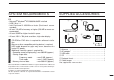
SYSTEM REQUIREMENTS PC • Microsoft® Windows® XP/2000/Me/98SE installed • USB 2.0 or 1.1 • Intel Pentium® III 450 MHz or faster (Pentium® 4 recommended) • At least 128 MB of memory or higher (256 MB or more recommended) • At least 50 MB or higher hard disk space • At least 1024 × 768 pixel resolution, high color display • CD-ROM or DVD drive is required for software installation. • Mouse or other compatible pointing device is required. • USB audio dropouts or gaps may occur, because of a lack of PC power.
PRECAUTIONS RWARNING! NEVER connect the OPC-254L to an AC outlet. This may pose a fire hazard or result in an electric shock. NEVER expose the receiver to rain, snow or any liquids. The receiver may be damaged. NEVER operate or touch the receiver with wet hands. This may result in an electric shock or damage the receiver. DO NOT leave the main unit powered ON and connected to a vehicle’s electrical system. The main unit draws approx. 550 mA. This will eventually drain the vehicle’s battery.
ABOUT APCO PROJECT 25 For the operation of PC and peripheral devices, follow the instructions provided in the manuals which come with the PC and peripheral devices. This device may cause signal interference when used in a domestic setting. When interference occurs, move this unit as far as possible away from the affected device. All copyrights associated with this manual and all intellectual property rights associated with the hardware and software of the IC-PCR1500/PCR2500 are held by Icom Inc.
TABLE OF CONTENTS FOREWORD …………………………………………… i IMPORTANT …………………………………………… i EXPLICIT DEFINITIONS ……………………………… i MOUSE PROPERTY SETTING ……………………… i SYSTEM REQUIREMENTS ………………………… ii SUPPLIED ACCESSORIES ………………………… ii PRECAUTIONS ……………………………………… iii ABOUT APCO PROJECT 25 ……………………… iv TABLE OF CONTENTS ……………………………… v v 1 INSTALLATION ……………………………… 1–3 ■ Hardware installation ………………………… 1 ■ TNC connection ………………………………… 2 ■ DC power supply connection ………………… 2 ■ Accessory attachments ……………………… 3 2 DRIVER IN
TABLE OF CONTENTS (Continued) ■ IF shift function………………………………… 61 ■ Weather channel operation (USA and CANADA versions only) ……………… 62 ■ Squelch delay setting ………………………… 63 ■ Single band/Dualwatch operation (IC-PCR2500 only) ……………………………… 64 ■ Diversity operation (IC-PCR2500 only) ……… 66 ■ Main/Sub band selection (IC-PCR2500 only) … 67 6 7 MEMORY CHANNELS …………………… 68–79 ■ General ………………………………………… 68 ■ Memory channel selection …………………… 68 ■ Memory channel programming ……………… 70 ■ Editing the memory list …………
TABLE OF CONTENTS (Continued) 11 OTHER FUNCTION …………………… 104–116 ■ DTMF Operation …………………………… 104 ■ Audio setting screen ………………………… 106 ■ Multi channel monitor ……………………… 110 ■ Recording operation ………………………… 112 ■ Sampling Rate setting ……………………… 114 ■ Remote recording function ………………… 115 ■ Short cut key operation …………………… 116 12 DSP OPERATION (Available only when the UT-106 is installed) ……… 117 ■ ANF function ………………………………… 117 ■ NR function ………………………………… 117 13 DIGITAL MODE OPERATION (IC-PCR2500 Main band
INSTALLATION 1 ■ Hardware installation 1 NOTE: The antenna’s double sided tape may not adhere to all items. Additionally, the tape is not intended for multiple uses. Lastly, some items may be damaged by trying to remove the antenna holder once it has been taped into place. Icom Inc cannot accept any responsibility for any damage to any item caused by the supplied tape. Refer to the diagram below for connections. CAUTION: Icom Inc.
1 INSTALLATION ■ TNC connection ■ DC power supply connection The IC-PCR1500/PCR2500 can receive 9600 bps packet communication (AFSK) with the use of a TNC (not supplied). Connect the TNC (Terminal Node Controller) as illustrated below. (Other connections are same as page 1.) Use a 12 V DC power supply with at least 1.2 A capacity. Make sure the ground terminal of the DC power supply is grounded. IC-PCR2500 white to an AC outlet TNC IC-PCR2500 Connect to a 12 V DC battery.
INSTALLATION ■ Accessory attachments 1 1 D Foot pad Attach 4 foot pads to the bottom of the IC-PCR1500/ PCR2500 as below. IC-PCR2500 Foot pad Foot pad sheet (supplied) Detach 4 foot pads from the foot pad sheet. D Cable hanger The cable hanger is convenient for fixing a cable to the wall, etc. Clinch the hook. Remove the protective paper.
2 DRIVER INSTALLATION The displayed dialog boxes or indications may differ slightly from the following instructions according to your system conditions, or environment. tThe CP2101 USB device is detected automatically, and the “Found New Hardware Wizard” will come up as below. Select “Install from a list or specific location (Advanced),” then click [Next>]. ■ Microsoft® Windows® XP NOTE: Driver installation with CD is required when an additional Main unit is connected to the PC (i.e.
DRIVER INSTALLATION ySelect “Search for the best driver in these locations.” then select “Include this location in the search,” click [Browse]. u Click “ 2 ” of the CD drive folder in “My Computer.” • The CD drive folder name (e.g. “D”) is depending on a PC. 2 Select Click Select Click iClick “ ” of the “Driver” folder in the CD drive folder, then select “Win” folder. Click [OK].
2 DRIVER INSTALLATION o Click [Next>]. !1 After the driver is found, the “Hardware Installation” dialog box appears as below. Click [Continue Anyway] to start the installation. Click !0 The Wizard starts searching for the driver and shows the dialog below during search. 6 Click !2 Windows starts installing the USB driver.
DRIVER INSTALLATION !3 After the installation is completed, click [Finish]. 2 !5 Select “Search for the best driver in these locations.” then select “Include this location in the search:”, click [Browse]. 2 Select Select Click Click !4 The “Found New Hardware Wizard” will come up again to install the USB serial port driver. Select “Install from a list or specific location (Advanced),” then click [Next>]. !6 Click “ ” of the CD drive folder in “My Computer.” • The CD drive folder name (e.g.
2 DRIVER INSTALLATION !7 Click “ ” of the “Driver” folder in the CD drive folder, then select “Win” folder. Click [OK]. !9 The Wizard starts searching for the driver and shows the dialog below during search. Select Click !8 Click [Next>]. @0 After the driver is found, the “Hardware Installation” dialog box appears as below. Click [Continue Anyway] to start the installation.
DRIVER INSTALLATION @1 Windows starts installing the USB driver. 2 @3 After clicking [Finish], the dialog appears as below. 2 @4 Eject the CD. • Restarting the PC is recommended. @2 After the installation is completed, click [Finish].
2 DRIVER INSTALLATION ■ Microsoft® Windows® 2000 NOTE: Driver installation with CD is required when an additional Main unit is connected to the PC (i.e. 2 or more ICPCR1500 or IC-PCR2500s (same model) are connected to the PC). In such a case, install the driver as shown below. tThe CP2101 USB device is detected automatically, and the “Found New Hardware Wizard” will come up as below. Click [Next>]. q Quit all applications when Windows is running.
DRIVER INSTALLATION uSelect “Specify a location,” then click [Next>]. 2 o Select the CD drive in “My Computer,” then click [Open]. • The CD drive folder name (e.g. “D”) is depending on a PC. 2 Click Select No check marks ✔ Click Click !0 Select the “Driver” folder in the CD drive, then click [Open]. iClick [Browse...].
2 DRIVER INSTALLATION !1 Select “Win” in the “Driver” folder, then click [Open]. !3 Click [OK]. Click Click Click !4 When the driver is found, the following dialog is displayed. Click [Next>] to start the installation. !2 Select “Slabbus” in the “Win” folder, then click [Open].
DRIVER INSTALLATION !5 After the installation is completed, click [Finish]. 2 !7 Select “Search for a suitable driver for my device (recommended),” then click [Next>]. 2 Select Click Click !6 The “Found New Hardware Wizard” appears again. Click [Next>]. !8 Select “Specify a location,” then click [Next>].
2 DRIVER INSTALLATION !9 Click [Browse...]. @1 Select the “Driver” folder in the CD drive, then click [Open]. Click Click Click @0 Select the CD drive in “My Computer,” then click [Open]. • The CD drive folder name (e.g. “D”) is depending on a PC. @2 Select “Win” in the “Driver” folder, then click [Open].
DRIVER INSTALLATION @3 Select “Slabw2k” in the “Win” folder, then click [Open]. 2 @5 When the driver is found, the following dialog is displayed. Click [Next>] to start the installation. 2 Click Click Click @4 Click [OK]. Click @6 After the installation is completed, click [Finish]. Click @7 Eject the CD. • Restarting the PC is recommended.
2 DRIVER INSTALLATION ■ Microsoft® Windows® 98SE q Quit all applications when Windows is running. wConnect the Main unit to the desired PC’s USB port with the supplied USB cable. ySelect “Search for the best driver for your device. (Recommended),” then click [Next>]. Select CAUTION: Icom Inc. assumes no responsibility for the receiver’s operation resulting from the use of any other USB cable other than the one supplied by Icom in the original IC-PCR1500 or IC-PCR2500 package.
DRIVER INSTALLATION i Click “ ” of the CD drive folder in “My Computer”. 2 !0 Click [Next>]. • The CD drive folder name (e.g. “D”) is depending on a PC. 2 Click Click o Select “Win” in the “Driver” folder, click [OK.] !1 When the driver is found, the following dialog is displayed. Click [Next>] to start the installation.
2 DRIVER INSTALLATION !2 After the installation is completed, click [Finish]. !4 Select “Search for the best driver for your device. (Recommended),” then click [Next>]. Select Click Click !3 The “Add New Hardware Wizard” appears again. Click [Next>]. !5 Select “Specify a location:”, click [Browse...].
DRIVER INSTALLATION !6 Click “ ” of the CD drive folder in “My Computer.” 2 !8 Click [Next>]. • The CD drive folder name (e.g. “D”) is depending on a PC. 2 Click Click !7 Select “Win” in the “Driver” folder, click [OK]. !9 When the driver is found, the following dialog is displayed. Click [Next>] to start the installation.
2 DRIVER INSTALLATION @0 After the installation is completed, click [Finish]. ■ Microsoft® Windows® Me q Quit all applications when Windows is running. wConnect the Main unit to the desired PC’s USB port with the supplied USB cable. Click @1 Eject the CD. • Restarting the PC is recommended. 20 CAUTION: Icom Inc. assumes no responsibility for the receiver’s operation resulting from the use of any other USB cable other than the one supplied by Icom in the original IC-PCR1500 or IC-PCR2500 package.
DRIVER INSTALLATION tThe CP2101 USB device is detected automatically, and the “Add New Hardware Wizard” will come up as below. Select “Specify the location of the driver (Advanced),” then click [Next>]. 2 ySelect “Search for the best driver for your device. (Recommended),” then select “Specify a location:”, click [Browse]. 2 Select Select Click Select Click u Click “ ” of the CD drive folder in “My Computer.” • The CD drive folder name (e.g. “D”) is depending on a PC.
2 DRIVER INSTALLATION i Select “WinMe” in the “Driver” folder, click [OK]. !0 When the driver is found, the following dialog is displayed. Click [Next>] to start the installation. Select Click Click o Click [Next>]. !1 After the installation is completed, click [Finish].
DRIVER INSTALLATION !2 The “Add New Hardware Wizard” appears again. Select “Specify the location of the driver (Advanced),” then click [Next>]. !4 Click “ ” of the CD drive folder in “My Computer.” 2 2 • The CD drive folder name (e.g. “D”) is depending on a PC. Click Click !5 Select “WinMe” in the “Driver” folder, click [OK]. !3 Select “Search for the best driver for your device. (Recommended),” then select “Specify a location:”, click [Browse].
2 DRIVER INSTALLATION !6 Click [Next>]. !8 After the installation is completed, click [Finish]. Click Click !7 When the driver is found, the following dialog is displayed. Click [Next>] to start the installation. Click 24 !9 Eject the CD. • Restarting the PC is recommended.
APPLICATION INSTALLATION 3 ■ Installation q Quit all applications when Windows is running. w Insert the CD into the CD drive. eOpen the CD drive contents via “My computer” or “Windows Explorer.” tSelect the display language type from “English” or “Japanese.” Click [Next>]. 2 3 • “Driver” and “Pcr1500_2500” folders are included. r Double click “Setup.exe” file in “Pcr1500_2500” folder. _2500 Click yAfter the preparation, the following dialog is displayed. Click [Next>].
3 APPLICATION INSTALLATION uConfirm the location, then click [Next>] to start the installation. i After the installation is completed, click [Finish]. • Click [Browse...] then type the desired location if you specifying the installation location. Click Click o Eject the CD. • The installation starts. 26 • The IC-PCR1500_2500 shortcut icon is created on the desktop. • Restarting the PC is recommended.
APPLICATION INSTALLATION 3 ■ Launching the IC-PCR1500_2500 D Microsoft® Windows® XP D Microsoft® Windows® 98SE/Me/2000 qBefore launching the program, please be sure the Main unit is turned ON. qBefore launching the program, please be sure the Main unit is turned ON. • The power indicator lights green. 3 • The power indicator lights green. wClick the [Start] button and point to [All Programs]. ePoint to the “IC-PCR1500_2500” folder. rClick the “IC-PCR1500_2500” program.
3 APPLICATION INSTALLATION ■ Uninstall In this section, screen shots of Windows XP are used for the instruction example. However, the instructions are similar to the other operating systems, Windows 98SE, Me and 2000. rClick the “Icom IC-PCR1500/2500,” then click [Change/Remove]. q Start up Windows. w Select the “Control Panel” in the Start menu. • The control panel appears as shown in the next step below. e Click the “Add or Remove Programs.” • The “Add or Remove Programs” menu appears.
APPLICATION INSTALLATION yAfter the preparation, “Confirm Uninstall” appears, click [OK] to remove the program from the PC. u After the uninstall is completed, click [Finish]. 3 3 Click • The uninstallation starts.
4 PANEL DESCRIPTION ■ Application screens (on PC screen) D Tool bar The application screen can be seen after the application installation. See page 25 for details. IC-PCR2500 q COMPONENT BUTTON (pgs. 37, 45) Click to display the Component screen. IC-PCR1500 w SIMPLE BUTTON (pgs. 36, 46) Click to display the Simple screen. !8 q !8 q !7 w !7 w !6 e !6 e !4 r !5 !4 !2 y !3 t !1 u !2 y !0 i !1 u !0 i u CLONE BUTTON (p. 130) Click to make the cloning screen appear/disappear.
PANEL DESCRIPTION !1 SETTING BUTTON For IC-PCR1500 (pgs. 55, 116) Click to make the auto mode setting list, short cut key list and etc. screen appear/disappear. For IC-PCR2500 (pgs. 55, 116, 119, 121) Click to make the auto mode setting list, short cut key list, DV*1 mode setting, P25*2 mode setting and etc. screen appear/disappear. *1: The optional UT-118 is required. *2: The optional UT-122 is required. Some versions already come with the UT-122 installed. !2 RECORDING BUTTON (p.
4 PANEL DESCRIPTION D [Receiver] (Multi-function receiver) screen e w q r $3 t $2 $1 y $3b u $8 $7 $6 $5 $4 i o !0 $0 #9 !1 IC-PCR2500 single band operation #8 !2 #7 !3 !6 !7 !8 !9 @0 @1 @2 @3 @4 #6 #5 !4 !5 @5 @6 @7 32 @8 @9 #0 #1 #2 #4 #3
PANEL DESCRIPTION q CLOSE BUTTON (p. 46) Click to quit and exit the application screen. w MINIMIZE BUTTON Click to minimize the application screen. eRECEIVE MODE BUTTONS ([SSB], [CW], [AM], [WFM], [FM], [DV]*1, [P25]*2 and [AUTO-M]) (pgs. 54, 55) Click to select a receive mode. • When using [AUTO-M] (automatic mode), a receive mode, IF filter passband width, tuning step, etc., are selected automatically after inputting a frequency. *1, *2 : For IC-PCR2500 only. *1 : The optional UT-118 is required.
4 PANEL DESCRIPTION !4 IF-SHIFT CONTROL (p. 61) Click to set a signal passband position. • Right-click to increase the signal passband position. • Left-click to decrease the signal passband position. • “WX” appears. !5 CENTER KEY [CENTER] (p. 61) After setting a signal passband position with clicking the IFshift control, click to return to the center position. @3 SCAN PAUSE BUTTON [❙ ❙] Push to pause/resume a scan. !6 IF FILTER BUTTONS [WIDE]/[NAR] (p. 58) Click to change the IF filter in use.
PANEL DESCRIPTION 4 @9 FREQUENCY BUTTON [FREQ] (p. 98) Click to show the receiving signal relative to signal strength while sweeping. #8 ATTENUATOR BUTTON [ATT] (p. 59) Click to turn the ATT (Attenuator) function ON or OFF. #0 TIME BUTTON [TIME] (p. 98) Click to show the received signal strength in the specified time period while sweeping. #9 NOISE BLANKER BUTTON [NB] (p. 60) Click to turn the NB (Noise Blanker) function ON or OFF. #1 REC BUTTON [●] (p. 100) Click to start saving the sweep data.
4 PANEL DESCRIPTION $3b DSQL SETTING BUTTON [DSQL] ➥ Click to turn the digital squelch ON or OFF. • Available only when DV *1 or P25 *2 mode is selected. ➥ When the digital squelch is turned ON, right-click to display the [DV Digital SQL] or [P25 Digital SQL] screen. D [Simple] screen The Simple screen buttons, controls, etc. operate the same as the Multi-function receiver screens. Please refer to the explanations on pages 33 to 36. Busy indicator (p. 40) *1, *2 : For IC-PCR2500 only.
PANEL DESCRIPTION 4 D [Compo] (Component) screen The Component screen buttons, controls, etc. operate the same as the Multi-function receiver screens. Please refer to the explanations on pages 33 to 36.
4 PANEL DESCRIPTION D Function display (on Multi-function receiver screen) q w e #2 r t y u i #1 #0 @9 o @3 !0 !1 !1 q TUNING STEP INDICATOR Indicates the tuning step digit. w FREQUENCY READOUT Indicates the receive frequency and data as it is being input such as memory channel numbers, etc. e TUNING STEP INDICATOR (p. 50) This is the frequency increment used when selecting a frequency using the tuning dial and when searching for signals using a scan function. r DUPLEX INDICATOR (p.
PANEL DESCRIPTION 4 o IF-SHIFT INDICATOR (p. 61) Indicates the received signal passband position. !7 ATTENUATOR INDICATOR [ATT] (p. 59) Appears when the ATT (Attenuator) function is ON. !0 IF-FILTER PASSBAND WIDTH INDICATOR (p. 58) Indicates the current signal passband width. !8 TSQL/DTCS INDICATOR [TSQL]/[DTCS] ➥ “TSQL” appears when the tone squelch frequency is set. (p. 94) ➥ “DTCS” appears when DTCS code and the polarity are set. (p. 95) !1 MAXIMUM FREQUENCY SPAN INDICATORS (p.
4 PANEL DESCRIPTION @5 RECEIVE MODE INDICATORS (p. 54) Indicate the current receive mode. @6 IF FILTER INDICATOR (p. 58) Indicates the selected IF filter. D Function display (on Simple screen) The function display indicators on the Simple screen operate the same as on the Multi-function receiver screens. Please refer to the explanations on pages 38 to 40. q @7 MUTE INDICATOR (p. 56) Appears when the squelch circuit mutes the received audio signal. w @8 MONITOR INDICATOR (p.
PANEL DESCRIPTION 4 D Function display (on Component screen) The function display indicators on the Component screen operate the same as on the Multi-function receiver screens. Please refer to the explanations on pages 38 to 40.
4 PANEL DESCRIPTION ■ Main unit D Front panel D Rear panel Speaker Power switch Rear q w DC IN Front i Front PACKET 1 PACKET 2 USB u y EXT SP t GND 2-conductor 3.5 (d) mm (1⁄8˝)/100 kΩ q e 2-conductor 3.5 (d) mm (1⁄8˝)/8 Ω IC-PCR1500 Rear r z POWER SWITCH [POWER] Turn the Main unit power ON and OFF. x POWER INDICATOR Lights green when the Main unit is turned ON.
PANEL DESCRIPTION q ANTENNA CONNECTORS Connect a 50 Ω antenna with a BNC connector and a 50 Ω coaxial cable. For IC-PCR2500 [ANT1] for Main band, [ANT2] for Sub band. For IC-PCR2500 Two antennas must be connected to [ANT1] and [ANT2] during dualwatch operation or diversity operation. Diversity operation requires two antennas of the same performance in suitable places. Ask your antenna dealer for installation details.
5 BASIC RECEIVE FUNCTIONS ■ Starting the control software ■ Changing the control screen qBefore launching the program, please make sure the Main unit is powered ON. Click the desired control screen’s icon on the tool bar. • The power indicator lights green. wLaunch the IC-PCR1500_2500 program. (p. 27) eClick the zPowerx icon on the tool bar to connect the control software and Main unit.
BASIC RECEIVE FUNCTIONS ➥ Click the zCompox icon for the Component screen.
5 BASIC RECEIVE FUNCTIONS ➥ Click the zSimplex icon for the Simple screen. IC-PCR1500 ■ Closing the control screen Click the close button ([X]) to close the control screen. • Click the close button (X) in each [TUNING PANEL], [MODE/VOL PANEL], [METER/SCAN PANEL] and [SCOPE PANEL] when the Component screen is displayed.
BASIC RECEIVE FUNCTIONS 5 ■ Receiving Make sure the hardware installation is finished (p. 1) and the Main unit is turned ON (p. 42). • [Receiver] screen IC-PCR1500 qClick the zPowerx icon on the tool bar to turn power ON. wClick the desired icon, zReceiverx, zCompox or zSimplex on the tool bar to select the displayed receiver screen type that you want to use. e Click zAF GAINx (zAFx)* to set the audio level. • Right-click to increase the audio level. • Left-click to decrease the audio level.
5 BASIC RECEIVE FUNCTIONS ■ Setting a frequency Depending on the situation, the receive frequency can be set using the following methods. Frequencies can be set from 0.010 to 3299.9999 MHz. D Using the PC keyboard ➥ Enter the desired frequency using the 10-keypad on the PC keyboard, then push [Enter] to set the frequency. • When inputting from the keyboard, click anywhere in the receiver screen first, then begin inputting the frequency.
BASIC RECEIVE FUNCTIONS • [Receiver] screen IC-PCR1500 5 10-KEYPAD IC-PCR2500 zDIALx 5 zCEx MAIN 10-KEYPAD z•x SUB 10-KEYPAD zENTx Active band only • [Compo] screen IC-PCR1500 IC-PCR2500 10-KEYPAD zDIALx TUNING 10-KEYPAD MAIN SUB 10-KEYPAD z•x zCEx zENTx Active band only • [Simple] screen IC-PCR1500 IC-PCR2500 zDIALx MAIN SUB 49
5 BASIC RECEIVE FUNCTIONS ■ Setting a tuning step When using the tuning dial to change the frequency, or when a scan function is activated, the frequency changes in increments determined by the set tuning step. The tuning step is adjustable. • [Receiver] screen IC-PCR1500 IC-PCR2500 The following tuning step are available: • 1 Hz • 10 Hz • 20 Hz • 50 Hz • 100 Hz • 500Hz • 1 kHz • 2.5 kHz • 5 kHz • 6.25 kHz • 8.33 kHz • 9 kHz • 10 kHz • 12.
BASIC RECEIVE FUNCTIONS Using [Simple] screen Click zTSx to display a tuning step list, then select the desired tuning step. • [Simple] screen IC-PCR1500 IC-PCR2500 MAIN 5 D Setting the user tuning step Right-click zYx(TS) or zZx(TS) (or click zTSx indication)* to display a tuning step list, then select “USER TS Setting...”. You can edit the desired tuning step from 0.001–9999.999 kHz (in 0.001 step) directly. *Available only when [Simple] screen is displayed.
5 BASIC RECEIVE FUNCTIONS ■ Audio level setting Using [Receiver]/[Compo] screen Click zAF GAINx to set the audio level. Using [Simple] screen Click zAFx to set the audio level. • Right-click to increase the audio level. • Left-click to decrease the audio level. • When clicking and holding zAF GAINx, the audio level scrolls up or down. • Push the PC’s [↑] (UP) or [↓] (DOWN) key also sets the audio level. • Right-click to increase the audio level. • Left-click to decrease the audio level.
BASIC RECEIVE FUNCTIONS 5 ■ Squelch level setting The squelch function sets a minimum receive signal level below which no audio is sent to the speaker. This prevents static or hiss from being heard through the speaker between transmissions. • [Receiver] screen IC-PCR1500 IC-PCR2500 5 A higher squelch setting removes weak signals. The remove level is displayed on the S-meter (S-meter squelch). The squelch does not open if a signal below the set S-meter level is received.
5 BASIC RECEIVE FUNCTIONS ■ Receive mode selection Receive modes are determined by the physical properties of the radio signals. The receiver has 5 receive modes: USB LSB, CW, AM, WFM and FM modes. The mode selection is stored independently in each memory channel. Additionally, IC-PCR2500 has a DV or P25 mode when the optional UT-118 or UT-122 units are installed, respectively. The IC-PCR2500’s Sub band can select AM, FM and WFM mode only. Typically, AM mode is used for the AM broadcast stations (0.495–1.
BASIC RECEIVE FUNCTIONS 5 ■ Automatic mode selection An automatic mode function is available to automatically set the receive mode, IF filter passband width, tuning step, etc. after inputting a frequency. wClick the [Auto Mode] tab to display the automatic mode list. 5 Using [Receiver]/[Compo] screen Each click of zAUTO-Mx toggles the automatic mode function ON and OFF.
5 BASIC RECEIVE FUNCTIONS ■ Monitor function This function is used to listen to weak signals without disturbing the squelch setting or to open the squelch manually even when mute functions such as the tone squelch are in use. • [Receiver] screen IC-PCR1500 IC-PCR2500 zMONIx zMUTEx Click zMONIx to monitor the operating frequency. • “MONI” appears when [Receiver]/[Compo] screen is displayed. • “MONI” button lights green when [Simple] screen is displayed.
BASIC RECEIVE FUNCTIONS 5 ■ Duplex operation Duplex communication uses one frequency for transmit, and a different frequency for receive. Generally, duplex is used in communication through a repeater, some utility communications, etc. • [Receiver] screen IC-PCR1500 zMONIx 5 During duplex operation, the transmit station frequency is shifted from the receive station frequency by the offset frequency. Repeater information (offset frequency and shift direction) can be programmed into memory channels. (p.
5 BASIC RECEIVE FUNCTIONS ■ IF filter selection The receiver has 2 to 4 IF passband filter widths for each mode. Selectable passband widths are 3, 6, 15, 50 and 230 (depending on the selected mode). • Selectable passband width for each mode. SSB mode : 2.8 kHz or 6 kHz CW mode : 2.8 kHz or 6 kHz AM mode : 2.8 kHz, 6 kHz, 15 kHz or 50 kHz WFM mode : 50 kHz or 230 kHz FM mode : 6 kHz, 15 kHz or 50 kHz Using [Receiver]/[Compo] screen Click zWIDEx or zNARx to select the desired IF filter widths.
BASIC RECEIVE FUNCTIONS 5 ■ AFC function The AFC (Automatic Frequency Control) function tunes the displayed frequency automatically when an off-center frequency is received. It activates in FM mode and IF filter setting is 6 or 15 kHz only. • [Receiver] screen IC-PCR1500 IC-PCR2500 zAFCx Click zAFCx to turn the AFC (Automatic Frequency Control) function ON or OFF.
5 BASIC RECEIVE FUNCTIONS ■ NB function The NB (Noise Blanker) function removes pulse-type noise when USB, LSB, CW or AM mode is selected. Note that the noise blanker is not effective against natural noise such as atmospheric static. • [Receiver] screen IC-PCR1500 IC-PCR2500 zNBx Click zNBx to turn the NB (Noise Blanker) function ON or OFF. • “NB” appears when the NB function is turned ON.
BASIC RECEIVE FUNCTIONS 5 ■ VSC function ■ IF shift function The VSC (Voice Squelch Control) function opens the squelch only when receiving a modulated voice signal. The IF shift function electronically changes the center of the IF (intermediate frequency) passband frequency to reject interference. It activates in SSB/CW modes only. • Not modulated signal (contain no voice or music, etc. components) are muted.
5 BASIC RECEIVE FUNCTIONS ■ Weather channel operation (USA and CANADA versions only) NOAA broadcast stations transmit weather alert tones before important weather announcements. When the weather alert function is turned ON, the selected weather channel is monitored each 5 sec. for the announcement. When the alert signal is detected, the “WX Alert” blinks and the WX channel is displayed, and sounds a beep tone until a change is made within the control screen, or the zWXx button is clicked.
BASIC RECEIVE FUNCTIONS 5 ■ Squelch delay setting • [Receiver] screen IC-PCR1500 Select squelch delay from short and long to prevent repeated opening and closing of the squelch during reception of the same signal. • Short : Short squelch delay. • Long : Long squelch delay. IC-PCR2500 MAIN SUB Appears Appears Blinks • [Compo] screen IC-PCR1500 IC-PCR2500 5 q Click the zSettingx icon on the tool bar to call up the [Setting] screen if it is not displayed.
5 BASIC RECEIVE FUNCTIONS ■ Single band/Dualwatch operation (IC-PCR2500 only) Dualwatch operation monitors two frequencies simultaneously. The IC-PCR2500 has two independent receiver circuits: Main band, and Sub band (available frequencies, operating mode and functions are different depending on bands). Single band operation is useful when only one frequency is being watched. The Sub band can be inhibited. The single band operation’s control screens are similar as the ICPCR1500.
BASIC RECEIVE FUNCTIONS • [Compo] screen Dualwatch operation • [Simple] screen Dualwatch operation Single band operation Single band operation 5 1 2 3 4 5 6 7 8 9 10 11 12 13 14 15 16 17 18 19 20 21 22 23 65
5 BASIC RECEIVE FUNCTIONS ■ Diversity operation (IC-PCR2500 only) The diversity receiving compares the receiving signal strength from two different antennas, ANT1 and ANT2, and automatically selects the strongest signal. This feature is useful when you are listening in a moving vehicle or the transmitting station itself is moving. Diversity receiving is available from 50 MHz to 1300 MHz on FM, P25 and DV mode only.
BASIC RECEIVE FUNCTIONS 5 ■ Main/Sub band selection (IC-PCR2500 only) • [Receiver] screen Some functions can be set to active band only depending on the control screen. Then you must select the desired band, Main band or sub band, to active band. ➥ Click the zMAINx (or zSUBx) icon on the tool bar to toggle the active band as Main band (or Sub band).
6 MEMORY CHANNELS ■ General ■ Memory channel selection The receiver has 2600 memory channels for storage of oftenused frequencies. There are total of 26 memory banks for usage by group, etc., and up to 100 channels can be assigned to a bank. D Selecting with the control screen D Memory channel contents The following information can be programmed into memory channels: • Memory channel name (p. 73) • Sub name (p. 73) • Operating frequency (p. 48) • Duplex direction (p. 57) • Offset frequency (p.
MEMORY CHANNELS • Direct channel number input on the [Receiver]/[Compo] screen Use the 10-keypad to input the desired memory channel number, then click zMchx to select the memory channel. • If a mistake is made when inputting a memory channel, click zCEx to clear the input and return to the previous frequency indication.
6 MEMORY CHANNELS ■ Memory channel programming 100 memory channels can be assigned to a memory bank. There are 26 memory banks. Any of the following information can be stored. • [Receiver] screen IC-PCR1500 IC-PCR2500 • Bank name, memory name, frequency, duplex direction, offset frequency, mode, filter, attenuator, tuning step, select memory scan, skip channel, squelch control setting and remark.
MEMORY CHANNELS • Using [Simple] screen q Click zYx(BANK) or zZx(BANK) to select a memory bank to be programmed. w Click zYx(MEMO) or zZx(MEMO) to select a pre-programmed memory channel to be programmed. NOTE: During [Simple] screen, you cannot set or change a receive frequency on a blank channel. e Set a frequency, mode, etc. that you want to memorize. r Click zMWx for 1 sec. to program the setting information into the selected memory channel.
6 MEMORY CHANNELS ■ Editing the memory list q Click the zMemory Editx icon on the tool bar to call up the [Memory Channel Editor] screen if it is not displayed. w Click zYx(BANK) or zZx(BANK) to select the desired memory bank. e Click the [Frequency] cell of the desired memory channel, then input the receive frequency from the keyboard. After inputting, push zEnterx. Program the receive frequency first, otherwise no setting can be made except for the name.
MEMORY CHANNELS 6 D About the [View] menu D Editing the memory channel name The indicated character size, sub name, TSQL/DTCS setting, DV setting, P25 setting indication can be set in [View] menu. q Click the zMemory Editx icon on the tool bar to call up the [Memory Channel Editor] screen if it is not displayed. w Click zYx(BANK) or zZx(BANK) to select the desired bank. e Select the desired channel, then double-click the [Name] or [Sub Name] cell.
6 MEMORY CHANNELS D Calling up the memory channel data from the control screen q Click the zMemory Editx icon on the tool bar to call up the [Memory Channel Editor] screen if it is not displayed. w Click zYx(BANK) or zZx(BANK) to select the desired memory bank. e Select the desired memory channel to call up the operating channel data on the control screen. r Click zMWx, or right-click a cell then click [MW] in the edit menu. • The operating channel data is called up to the [Memory Channel Editor] screen.
MEMORY CHANNELS 6 D Memory channel insert/delete D Bank name programming Insert: New blank channels can be inserted into the channel list. Channels below the cursor are shifted down automatically. Delete: Unnecessary channels can be deleted from the list. Channels below the cursor are shifted up automatically. Each memory bank can be programmed with an alphanumeric bank name for easy recognition and can be indicated independently. Names can be set with a maximum of 64 characters.
6 MEMORY CHANNELS D Selecting a bank with the programmed name Each memory bank can be selected with the programmed name from a bank name dialog box. q Click the zMemory Editx icon on the tool bar to call up the [Memory Channel Editor] screen if it is not displayed. w Click [Z] to display a memory bank name list as below. e Click the desired bank name to select the bank. • The [Memory Channel Editor] screen contents changes to the selected bank’s.
MEMORY CHANNELS 6 D Clearing from the memory list • [Compo] screen IC-PCR1500 IC-PCR2500 MAIN TUNING MEMO zYx/zZx BANK zYx/zZx SUB zMCLx IC-PCR1500 • [Simple] screen IC-PCR1500 q Click the zMemory Editx icon on the tool bar to call up the [Memory Channel Editor] screen if it is not displayed. w Click zYx(BANK) or zZx(BANK) to select a memory bank. e Right click the cell of the unneeded memory channel to be cleared, then click [Clear] from the displayed menu.
6 MEMORY CHANNELS ■ Saving memory channel data The memory channels can be stored as a PC file. Click [Save] or [Save As...] in the [File] menu to back up memory channel data. • Save • Save As... : Saves current project as a PC file. Overwritten if previously saved file of the same name exist. : Saves with a different file name. ■ Creating new memory channel data file The new memory channel data file can be created. Click [New] in the [File] menu to make a new memory channel data file.
MEMORY CHANNELS 6 ■ Importing a CSV file ■ Exporting a CSV file The CSV (Comma Separated Values) format file (which is saved in CSV format) can be imported and overwrite to the selected bank contents. The selected bank contents are exportable in CSV (Comma Separated Values) file format. NOTE: Save the current contents as a PC file (p. 68) before importing a CSV file. Once the imported CSV file is overwritten, previously set contents are no longer available. qClick [Import...] in the [File] menu.
7 SCAN OPERATION (Multi-function receiver/Component screens only) ■ Scan types Up to 50 programmed scan ranges, memory scan, memory select scan, memory skip scan, mode select memory scan and auto memory write scan provide scanning versatility. PROGRAMMED SCAN (p. 81) Scan edges Scan Jump SELECT MEMORY SCAN (p. 88) Not yet programmed ch 1 ch 50 ch 2 SEL ch 3 SEL ch 4 SEL ch 49 ch 6 ch 5 SEL SEL SEL MODE SELECT MEMORY SCAN (p.
SCAN OPERATION (Multi-function receiver/Component screens only) 7 ■ Programmed scan Programmed scan automatically searches for signals within a specified frequency range. • [Receiver] screen IC-PCR1500 IC-PCR2500 For programmed scan, scan edges must be programmed in advance. D Programming scan edge channels Set the scan edge channel name, frequency range and ATT in advance. Up to 50 settings can be programmed.
7 SCAN OPERATION (Multi-function receiver/Component screens only) D Skip area setting D Starting a programmed scan The skip area setting is available for skipping unwanted frequencies that inconveniently stop scanning. qMake sure the squelch is set to the threshold point (closed condition). wRight-click the zPROGx button to call up the [Program Scan] setting screen if it is not displayed. eClick the [Program Scan] tab to show the program list.
SCAN OPERATION (Multi-function receiver/Component screens only) 7 tClick the zPROGx button to start programmed scan. • “PROG Scan” blinks and [PROG] appears while scanning. yTo stop the scan, click zSTOPx or zPROGx. • When the frequency is changed after cancelling a scan and a new scan is activated, scanning starts from the starting frequency of the specified frequency range. When the frequency is not changed, scan starts from the previously stopped frequency.
7 SCAN OPERATION (Multi-function receiver/Component screens only) ■ Auto memory write scan The auto memory write scan does the same as the programmed scan and then writes paused signal frequencies into memory channels of a specified memory bank. Scan edges must be programmed in advance. (p. 81) eEnter the programmed scan range number to be scanned in [Program No]. rSelect a memory bank to be written, then click the close ([X]) button to close the setting screen.
SCAN OPERATION (Multi-function receiver/Component screens only) 7 tClick zAUTOx to start auto memory write scan. • “AUTO Scan” blinks and [AUTO] appears while scanning. yTo stop the scan, click zSTOPx or zAUTOx.
7 SCAN OPERATION (Multi-function receiver/Component screens only) ■ Memory/bank scan This function searches all memory channels in a selected memory bank. • [Compo] screen IC-PCR1500 IC-PCR2500 D Starting a memory/bank scan q Make sure the squelch is set to the threshold point (closed condition). w Click zYx(BANK) or zZx(BANK) to select the desired memory bank. eRight-click the zMEMOx button to call up the [Memory Scan] setting screen if it is not displayed.
SCAN OPERATION (Multi-function receiver/Component screens only) 7 y Click the zMEMOx button to start memory scan. • “MEMO Scan” blinks and [MEMO] appears while scanning. u To stop the scan, click zSTOPx or zMEMOx.
7 SCAN OPERATION (Multi-function receiver/Component screens only) ■ Versatile memory scan You can set the memory scan conditions using the [Memory Scan] setting screen. qRight-click the zMEMOx button to call up the Memory Scan setting screen if it is not displayed. • [Receiver] screen IC-PCR1500 IC-PCR2500 wCheck the desired check boxes, then click the close ([X]) button to close the setting screen.
SCAN OPERATION (Multi-function receiver/Component screens only) eClick the zMEMOx button to start the desired memory scan. • “MEMO Scan” blinks and [MEMO] appears while scanning. rTo stop the scan, click zSTOPx or zMEMOx. • [Receiver] screen IC-PCR1500 7 • All settings can be used simultaneously. • SEL, SKIP and receive mode can be set in the memory list screen. • At least 2 memory channels must be programmed with the desired condition for scan to proceed.
7 SCAN OPERATION (Multi-function receiver/Component screens only) ■ Scan resume condition When receiving a signal, scanning automatically pauses on that signal. The scan resume condition sets the time that the scan pauses before resuming or whether scan stops instead of pausing. qClick the zSETx button to call up the [Scan Delay] screen if it is not displayed. wSelect the scan delay condition from ‘Pause until Signal Disappears,’ ‘Delay Volume’ or ‘Scan Stop.
SCAN OPERATION (Multi-function receiver/Component screens only) 7 ■ Scan speed setting The searching speed of frequencies or memory channels is variable. Click the zSPEEDx control to set the speed at which scans search through frequencies/memories for signals. • Right-click to increase the speed level. • Left-click to decrease the speed level. • When clicking and holding zSPEEDx, the scan speed scrolls up or down.
8 PRIORITY SCAN (Multi-function receiver/Component screens only) ■ Priority scan type ■ Priority scan operation The priority scan checks for signals on the frequency every 5 sec. while operating on a scanning memory channel or scanning. qSet the receive frequency. (p. 48) wRight-click the zPRIOx button to call up the [Priority Scan] setting screen if it is not displayed. The scan resumes according to the selected scan resume condition. See p. 90 for details.
PRIORITY SCAN (Multi-function receiver/Component screens only) eSet the scanning channel and bank in [Scan Channel]. rSet the scanning interval from 2 to 60 sec in [Priority Interval], then click the close ([X]) button to close the setting screen. • Click zCHECKx to monitor the selected priority channel. • Click zOFFx to stop monitoring the priority channel. t Click zPRIOx button to start priority scan. • “PRIO Scan” blinks and [PRIO] appears while scanning.
9 TONE SQUELCH OPERATION (Multi-function receiver/Component screens only) ■ Tone/DTCS operation The tone or DTCS opens only when receiving a signal with the same pre-programmed subaudible tone or DTCS code, respectively in FM mode. You can silently wait for the specified signal using the same tone. • [Receiver] screen IC-PCR1500 zTSQLx D Tone squelch frequency setting Active band only qClick zFMx to select FM mode. wClick zTSQLx to turn the tone squelch ON. • “TSQL” appears in the function display.
TONE SQUELCH OPERATION (Multi-function receiver/Component screens only) 9 D DTCS code setting qClick zFMx to select FM mode. wClick zDTCSx to turn the DTCS squelch ON. • [Receiver] screen IC-PCR1500 IC-PCR2500 • “DTCS” appears in the function display. eRight-click zDTCSx to display the [DTCS] setting screen. rClick zZx to select the desired DTCS code. zDTCSx • 104 DTCS code from 023 to 754 are available.
9 TONE SQUELCH OPERATION (Multi-function receiver/Component screens only) ■ DTCS polarity setting ■ Pocket beep operation As well as a code setting, the polarity setting is also available for the DTCS operation. When a different polarity is set, the DTCS never releases audio mute even when a signal with a matching code number is received. This function uses subaudible tones for calling and can be used as a “common pager” to inform you that someone has called while you were away from the receiver.
TONE SQUELCH OPERATION (Multi-function receiver/Component screens only) 9 ■ Tone scan operation By monitoring a signal using with pocket beep, tone or DTCS squelch, you can determine the tone frequency or DTCS code necessary to open the squelch. qClick zFMx to select FM mode. wSelect the tone type, tone squelch or DTCS to be scanned, then set the desired tone squelch frequency or DTCS code. (pgs. 94, 95) eClick zT-SCANx to start the tone scan. • “AUTO Scan” blinks and zAUTOx appears while scanning.
10 BAND SCOPE (Multi-function receiver/Component screens only) ■ Operation The band scope function has 2 modes, Frequency and Time modes. When Frequency mode is selected, the band scope function sweeps in the specified span from the displayed frequency and allows you to visually check the received signal strength on the function display. When Time mode is selected, the band scope function displays the received signal strength in the specified time period on the function display while sweeping.
BAND SCOPE (Multi-function receiver/Component screens only) 10 D About the limit indicator When a selected sweep tuning step is outside the automatic sweep step setting (p. 102), “LIMIT” appears in the band scope display during the band scope operation.
10 BAND SCOPE (Multi-function receiver/Component screens only) ■ Pick up signal function ■ Saving the sweep data The pick up signal function provides quick frequency setting during the band scope operation. By clicking the desired waveform, the clicked point frequency is set to the receive frequency. The band scope sweep data can be saved in CSV (Comma Separated Values) file format. While pausing the band scope, you can also select the displayed signal frequency by clicking the waveform.
BAND SCOPE (Multi-function receiver/Component screens only) • [Receiver] screen IC-PCR1500 10 When Time mode is selected. IC-PCR2500 Right click zTIMEx Active band only zTIMEx zSTOPx Click to select the desired save time interval. 10 zSTARTx zRECx Click • [Compo] screen IC-PCR1500 IC-PCR2500 METER/SCAN Active band only zTIMEx zSTARTx q Select the desired folder.
10 BAND SCOPE (Multi-function receiver/Component screens only) ■ Changing the automatic sweep step limit The frequency steps used while sweeping are automatically set according to the tuning step. However, these steps can be defined using the [Scope (FREQ)] setting screen on the setting screen. qRight-click the zFREQx button to call up the [Scope (FREQ)] setting screen if it is not displayed. wClick the desired frequency step range in the [Automatic Sweep Step Limit].
BAND SCOPE (Multi-function receiver/Component screens only) 10 ■ Wide band scope function ■ Band scope options The wide band scope function is available to sweep a wide band scope (±1, 2 or 5 MHz.) While sweeping the band scope, AF monitor function is also available. The following optional functions are available for the band scope function. These settings can be defined using the [Scope (FREQ)] screen. qRight-click the zFREQx button to call up the [Scope (FREQ)] setting screen if it is not displayed.
11 OTHER FUNCTIONS ■ DTMF Operation The control software can be remotely controlled using DTMF codes in FM mode. When receiving a programmed DTMF code, the control software displays a message, activates a program/screen saver or plays a Windows sound file. IC-PCR1500 Only the IC-PCR2500 or IC-R2500 can be installed optional UT-108 DTMF DECODER unit. When the IC-PCR2500 or ICR2500 is installed the optional UT-108, DTMF operation for sub band is available. q Click zFMx to select FM mode.
OTHER FUNCTIONS 11 D Setting the DTMF receive code q Click the zDTMFx icon on the tool bar to call up the [DTMF Remote Commander] screen if it is not displayed. w Click zSETx to call up the receive code setting screen. e Click the desired tab from z1x to z5x for the receive code setting, then enter the desired key code in the [Receive CODE] field using the keyboard. • [DTMF Remote Commander] screen The received DTMF code is displayed. q Click t Click • 0 to 9, A, B, C, D, E (∗) and F (#) can be used.
11 OTHER FUNCTIONS ■ Audio setting screen The Audio Setting screen adjusts the audio level and mute condition of the Main unit and the connected PC, and also, the confirmation beep ON/OFF, the pocket beep emission type and the pocket beep repeating times can be set. • [Audio setting] screen IC-PCR1500 D The AF gain/mute setting q Click the zAudio Settingx icon on the tool bar to call up the [Audio Setting] screen if it is not displayed.
OTHER FUNCTIONS D Beep settings ● Confirmation Beep This function sets the confirmation beep ON or OFF. ● Pocket Beep This function sets the pocket beep emission type. ● Repeat (1–60) This function sets the number of times for pocket beep repeating. q Call up the [Audio Setting] screen if it is not displayed as at left. wCheck the [Confirmation Beep] check box to turn the confirmation beep emission ON. eEnter the wave file name in the [Pocket Beep] text box directly, or click [...
11 OTHER FUNCTIONS D When playing through the computer’s speaker The [Audio Device] setting is necessary when the audio is emitted via the built-in or connected PC speaker whenever the USB cable is connected. NOTE: The sound board should be installed into the PC to hear sound via the PC speaker. Please refer to your PC’s instruction manual for details. q Click the zPowerx icon on the tool bar to disconnect the Main unit, then turn the Main unit’s power OFF. • The power indicator of the Main unit goes out.
OTHER FUNCTIONS ● Microsoft® Windows® 2000/Me wClick the [Start] button and click [Control Panel] in [Settings]. eDouble click on [Sounds and Maltimedia], then click the [Audio] tab. rConfirm the “Preferred device” in [Sound Playback]. • Making a note is recommended. tClick the close button ([X]) to close the [Sounds and Maltimedia Properties] screen. 11 ● Microsoft® Windows® 98SE wClick the [Start] button and click [Control Panel] in [Settings].
11 OTHER FUNCTIONS ■ Multi channel monitor The receiver has 250 multi channels. A total of 10 memory banks are available for usage by group, etc., and 25 channels are assigned into a bank. The multi channel monitor function scans the programmed multi channels, and makes you to check the received signal strength level on the channels visually.
OTHER FUNCTIONS 11 D Multi channel monitor operation q Click the zMulti CH Monitorx icon on the tool bar to call up the [Multi CH Monitor] screen if it is not displayed. During scanning • The channel name and frequency are displayed on the programmed channel. w Click zZx to select the desired bank to monitor. eClick the zSTARTx button to start scan. While scanning, the receive audio is muted. • “SCANNING” blinks in the information box. • The zSTARTx button changes to the zSTOPx button while scanning.
11 OTHER FUNCTIONS ■ Recording operation The receiver has a recorder function that enables you to record a signal. The recording data can be saved into the PC. D Recording a receiving signal q Receive a signal. (p. 47) w Click the zRecordingx icon on the tool bar to call up the [Recording] screen if it is not displayed. IC-PCR1500 • [Recording] screen IC-PCR1500 q Click IC-PCR2500 q Click IC-PCR2500 zRecordingx w Click w Click eClick zSettingx to display the setting menu. rClick [...
OTHER FUNCTIONS • [Recording] screen (While recording) IC-PCR1500 zPAUSEx Recording counter zRECx File name 11 D Stereo Recording (IC-PCR2500 only) You can record the receiving signal as stereo sound. The Main and Sub bands must be set to the same frequency. • [Recording] screen IC-PCR2500 w Click the zRECx button. (Only Main side is enabled.) zSTOPx IC-PCR2500 zPAUSEx Recording counter q Check the box to turn the stereo recoding function ON.
11 OTHER FUNCTIONS ■ Sampling Rate setting Sampling Rate setting is expressed in samples per second, and determines the sound quality. Although a higher sampling rate provides a better quality sound than a lower sampling rate, the file size becomes larger. q Receive a signal. (p. 47) w Click zRecordingx icon on the tool bar to call up the [Recording] screen if it is not displayed.
OTHER FUNCTIONS 11 ■ Remote recording function The remote recording function pauses recording automatically when no signal is received, and resumes after the signal appears. q Receive a signal. (p. 47) w Click the zRecordingx icon on the tool bar to call up the [Recording] screen if it is not displayed. IC-PCR1500 • [Recording] screen IC-PCR1500 IC-PCR2500 q Click IC-PCR2500 q Click zRecordingx e Click zSettingx to display the setting menu.
11 OTHER FUNCTIONS ■ Short cut key operation Shortcut keys give you faster and easier operation from a PC key board. q Click y Click D A shortcut key assignment q Click the zSettingx icon on the tool bar to call up the [Setting] screen if it is not displayed. w Click the zShortcutx tab to display the shortcut key list. e Select the category from ‘General,’ ‘Tuning,’ ‘Mode,’ ‘Scan’ and ‘Recording’ in [Category]. r Select the desired action in [Action].
DSP OPERATION (Available only when the UT-106 is installed) 12 ■ ANF function ■ NR function The ANF (Automatic Notch Filter) function automatically attenuates beat tones, tuning signals, etc., even if they are moving. This function can be activated in SSB, AM, FM modes. The NR (Noise Reduction) function reduces noise components and picks out desired signals which are buried in noise. The received AF signals are converted to digital signals and then the desired signals are separated from the noise.
13 DIGITAL MODE OPERATION (IC-PCR2500 Main band only) ■ Digital mode operation The IC-PCR2500 can operate in DV*1 mode or P25*2 mode when the optional UT-118 or UT-122 is installed. *1: The optional UT-118 is required. *2: The optional UT-122 is required. Some versions come with the UT-122 installed. • [Receiver] screen Single band ➥ Click the zMAINx icon on the tool bar to select the Main band.
DIGITAL MODE OPERATION (IC-PCR2500 Main band only) 13 ■ DV mode setting The IC-PCR2500 can receive the signals in DV* mode and low-speed data. If the transmit signal is included the GPS data, position data receiving is available. • [Setting] screen e Click q Click *The optional UT-118 is required. q Click the zSettingx icon on the tool bar to call up the [Setting] screen if it is not displayed. w Click the zDVx tab to display the DV setting.
13 DIGITAL MODE OPERATION (IC-PCR2500 Main band only) Multi-function receiver/Component screens only ■ DV digital squelch function • [Receiver] screen Single band Dualwatch While in DV mode operation, the digital call sign (DSQL) or digital code squelch opens only when receiving a voice signal with the same pre-programmed digital call sign or code, respectively. D Digital squelch setting qClick zDVx to select DV mode. wClick zDSQLx to turn the digital squelch ON.
DIGITAL MODE OPERATION (IC-PCR2500 Main band only) 13 ■ P25 mode setting The IC-PCR2500 can receive in P25* mode. *The optional UT-122 is required. Some versions already come with the UT-122 installed. q Click the zSettingx icon on the tool bar to call up the [Setting] screen if it is not displayed. w Click the zP25x tab to display the P25 setting. • [Setting] screen q Click e Click w Set the setting zSettingx Select the optional unit power setting.
13 DIGITAL MODE OPERATION (IC-PCR2500 Main band only) ■ P25 digital squelch function Multi-function receiver/Component screens only While in P25 mode operation, 2 types of digital squelch, NAC or Selective, are available. D Digital squelch setting qClick zP25x to select P25 mode. wClick zDSQLx to turn the digital squelch ON. • [Receiver] screen Single band Dualwatch • “NAC” (or “SEL”) appears in the function display. eRight-click zDSQLx to display the [P25 Digital SQL] setting screen.
DIGITAL MODE OPERATION (IC-PCR2500 Main band only) 13 ■ Digital menu indication Click the zDigitalx icon on the tool bar to display the DV digital menu and/or P25 digital menu. • [P25 Digital SQL] screen NAC squelch r Click Enter the digital code. e Check the check box to turn the [Pocket Beep] ON. q Click to select the squelch type. Selective squelch r Click Enter the digital code. e Check the check box to turn the [Pocket Beep] ON. q Click to select the squelch type.
13 DIGITAL MODE OPERATION (IC-PCR2500 Main band only) D DV Digital menu D P25 Digital menu • [DV Received call record] screen Click to clear the received call record. Click to creat the log file in CSV format. Click to export the CSV format file. Check the box to turn the DV Received call record screen automatically, when the signal with a new call sign is received. • [P25 Received call record] screen Click to clear the received call record. Click to creat the log file in CSV format.
OPTIONAL UNIT INSTALLATION AND OTHER ■ Opening the top cover 14 ■ UT-106 installation CAUTION: DISCONNECT the AC adaptor or DC power cable from the receiver Main unit before performing any work on the receiver. The optional UT-106 DSP RECEIVE UNIT provides AF DSP (Digital Signal Processor) functions such as ANF (Auto Notch Filter) and NR (Noise Reduction). qTurn the receiver Main unit power OFF, then disconnect the AC adaptor or DC power cable.
14 OPTIONAL UNIT INSTALLATION AND OTHER rConnect P1 (4 pin) of the UT-106 to J16 of the LOGIC board. UT-106 yRemove the protective paper from the supplied velcro®, then attach it to the UT-106 and the shield case of MAIN board. Protective paper Velcro J16 UT-106 P1 tConnect the supplied flat cable between J3 of the UT-106 and J15 of the LOGIC board. Velcro • Be sure not upside down. MAIN board J3 Flat cable J15 uReplace the top cover, cables and screws to the original position.
OPTIONAL UNIT INSTALLATION AND OTHER ■ UT-108/UT-118/UT-122 installation ( IC-PCR2500/R2500 only) qRemove the top cover as shown on p. 126. w Connect the UT-108, UT-118 or UT-122 as shown below. 14 ■ INTERNAL AUDIO SWITCH The internal switch must be set properly to use an external speaker, headphones or earphone. qRemove the top cover as shown on p. 126. wSet the switch as shown below. • Set the switch to [SPEAKER] when an external speaker is connected to the receiver.
15 USB PORT SETTING ■ USB port setting The connected PC’s USB port number and the serial number of the Main unit can be selected/confirmed in [Port Setting] screen. If some receiver’s main units are connected to your PC, select the desired USB port and serial number when the ICPCR1500/PCR2500 power is OFF. The only one Main unit can be operated. 2 or more Main units cannot be operated simultaneously.
USB PORT SETTING 15 ■ USB audio setting USB audio output function can be turned ON or OFF in [Port Setting] screen when the IC-PCR1500/PCR2500 power is OFF. When the USB audio output function is OFF, the audio/mute setting for PC, recording function (pgs. 106, 112) are disabled, but the computer running speed will be faster than when the USB audio output function is ON. qClick zPowerx icon on the tool bar to disconnect the Main unit.
16 CLONING OPERATION (Available only when the IC-R1500 or IC-R2500 is connected) ■ Launching the cloning software q Launch the IC-PCR1500_2500 program. (p. 27) w Click the zPowerx icon on the tool bar to connect the control software and Main unit, if it is disconnected. e Click the zClonex icon on the tool bar to call up the Cloning screen (described left).
CLONING OPERATION e CLONING MENU [Clone] • Click to display the cloning menu. • Click [Information] to display the cloning information dialog box. r OPTION MENU [Option] Click to display the convert menu. t TOOL BAR Shortcut buttons appear on the tool bar when the tool bar indication is turned ON in the [View] menu. Creates a new setting project. Loads a saved ICF (Icom Cloning Format) file. Saves current project as an ICF file. Reads the data from the Main unit. Writes the data to the Main unit.
16 CLONING OPERATION ■ Data convert D Converting the PC operation’s data to the controller operation’s data q Click [Convert] in the [Option] menu to display the convert menu. Then select [PC -> Receiver] (or click “ ”.) w Set the option items (A to G), click [START] to start converting. A B C D E F G H A Check the check box to convert the PC operation’s memory channel data to the controller operation’s data.
CLONING OPERATION 16 D Converting the controller operation’s data to the PC operation’s data q Click [Convert] in the [Option] menu to display the convert menu. Then select [Receiver -> PC] (or click “ ”.) w Set the option items (A to P), click [START] to start converting. A B C D E F G H I J L M N O P Q K A Check the check box to convert the controller operation’s memory channel data to the PC operation’s data.
16 CLONING OPERATION H Check the check box to keep the PC operation’s Bank name settings. • If it is not checked, the Bank name settings will be blanked after converting. I Check the check box to convert the Program Scan Edge settings. J Check the check box to keep the PC operation’s Program Scan name settings. • If it is not checked, the Program Scan name settings will be blanked after converting. K Check the check box to keep the PC operation’s Program Scan ATT settings.
TROUBLESHOOTING 17 If your receiver seems to be malfunctioning, please check the following points before sending it to a service center. PROBLEM Does not turn on. POSSIBLE CAUSE SOLUTION • The AC adapter is not fully seated in the power • Check the connection. jack on the Main unit’s rear panel. • An AC adapter is connected to the same AC outlet • Check the connection. with a PC, printer, etc. No sound comes from the • Volume is too low. speaker. • The audio mute function is activated.
18 SPECIFICATIONS AND OPTIONS ■ Specifications D GENERAL • Frequency coverage (MHz) U.S.A. : 0.010000–809.999999 *1, *2 851.000–866.999999 896.000–1300.000000 1300.000001–1810.999999 *1 1852.000–1867.999999 *1 1897.000–2305.899999 *1 2357.000–2811.999999 *1 2853.000–2868.999999 *1 2898.000–3109.799999 *1, *2 3136.000–3154.799999 *1, *2 3181.000–3299.999999 *1, *2 France : 0.010000–29.999999 *1, *2 50.200–51.200000 87.500–107.999999 144.000–146.00000 430.000–440.00000 1240.000–1300.
SPECIFICATIONS AND OPTIONS • Sensitivity: FM (1 kHz/3.5 kHz Dev.; 12 dB SINAD) 28.000–29.999 MHz : Less than 0.63 µV 30.000–49.999 MHz : Less than 0.63 µV 50.000–239.999 MHz : Less than 0.5 µV 240.000–279.999 MHz : Less than 0.5 µV 280.000–299.999 MHz : Less than 0.5 µV 300.000–699.999 MHz : Less than 0.5 µV 700.000–1300.000 MHz : Less than 0.63 µV 1300.000001–2299.999 MHz: Less than 5.6 µV 2300.000–3000.000 MHz : Less than 18 µV WFM (1 kHz/52.5 kHz Dev.; 12 dB SINAD) 50.000–699.999 MHz : Less than 1.
19 DOC DECLARATION OF CONFORMITY We Icom Inc. Japan 1-1-32, Kamiminami, Hirano-ku Osaka 547-0003, Japan Declare on our sole responsibility that this equipment complies with the essential requirements of the Radio and Telecommunications Terminal Equipment Directive, 1999/5/EC, and that any applicable Essential Test Suite measurements have been performed. Kind of equipment: Type-designation: COMMUNICATIONS RECEIVER iPCR1500/R1500 Düsseldorf 5th Dec.
DOC DECLARATION OF CONFORMITY We Icom Inc. Japan 1-1-32, Kamiminami, Hirano-ku Osaka 547-0003, Japan Declare on our sole responsibility that this equipment complies with the essential requirements of the Radio and Telecommunications Terminal Equipment Directive, 1999/5/EC, and that any applicable Essential Test Suite measurements have been performed. Kind of equipment: Type-designation: COMMUNICATIONS RECEIVER iPCR2500/R2500 Düsseldorf 24th Mar.
IC-PCR1500 #22 Europe ■ GER ■ FRA ■ ESP ■ SWE ■ AUT ■ NED IC-PCR2500 ■ GBR ■ BEL #22 Europe ■ IRL ■ LUX ■ POR ■ ITA ■ GRE ■ DEN ■ FIN ■ SUI ■ NOR IC-PCR1500 #23 U.K. ■ GER ■ FRA ■ ESP ■ SWE ■ AUT ■ NED IC-PCR2500 ■ GBR ■ BEL #23 U.K.