INSTRUCTION MANUAL COMMUNICATIONS RECEIVER iR20 This device complies with Part 15 of the FCC rules. Operation is subject to the following two conditions: (1) This device may not cause harmful interference, and (2) this device must accept any interference received, including interference that may cause undesired operation. WARNING: MODIFICATION OF THIS DEVICE TO RECEIVE CELLULAR RADIO TELEPHONE SERVICE SIGNALS IS PROHIBITED UNDER FCC RULES AND FEDERAL LAW.
FOREWORD IMPORTANT Thank you for purchasing this Icom product. The IC-R20 COMMUNICATIONS RECEIVER is designed and built with Icom’s superior technology and craftsmanship. With proper care, this product should provide you with years of trouble-free operation. READ ALL INSTRUCTIONS carefully and completely We want to take a couple of moments of your time to thank you for making your IC-R20 your radio of choice, and hope you agree with Icom’s philosophy of “technology first.
PRECAUTION RWARNING! NEVER operate the receiver with an earphone, headphones or other audio accessories at high volume levels. Hearing experts advise against continuous high volume operation. If you experience a ringing in your ears, reduce the volume level or discontinue use. RWARNING! NEVER connect the receiver directly to an AC outlet. This may pose a fire hazard or result in an electric shock. RWARNING! NEVER operate the receiver while driving a vehicle.
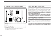
SUPPLIED ACCESSORIES q w e r OPERATING THEORY Electromagnetic radiation which has frequencies of 20,000 Hz (20 kHz*) and above is called radio frequency (RF) energy because it is useful in radio transmissions. The ICR20 receives RF energy from 0.150 MHz* to 3304.999 MHz and converts it into audio frequency (AF) energy which in turn actuates a loudspeaker to create sound waves. AF energy is in the range of 20 to 20,000 Hz.
TABLE OF CONTENTS FOREWORD ................................................... i IMPORTANT ................................................... i EXPLICIT DEFINITIONS ................................ i PRECAUTION ................................................ ii SUPPLIED ACCESSORIES .......................... iii OPERATING THEORY .................................. iii OPERATING NOTES .................................... iii TABLE OF CONTENTS ................................ iv QUICK REFERENCE GUIDE .......
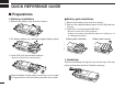
QUICK REFERENCE GUIDE ■ Preparations D Batteries installation D Battery pack installation qRemove the battery cover from the receiver. q Remove the battery cover from the receiver. w Remove the supplied battery spacer for R6 (AA) size battery use. e Install the Li-Ion battery pack (BP-206). • Be sure to observe the correct direction. • Charge Li-Ion battery pack (BP-206) before use. (Refer to p. IV for charging instructions.) wFor alkaline battery use, attach the supplied battery spacer.
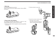
D Belt clip Conveniently attaches to your belt. Attach the belt clip with the supplied screws using a phillips screwdriver. D Swivel belt clip (Option) The optional swivel belt clip (MB-86) is useful for easy attaching/detaching the receiver to/from the belt. q Attach the stopper with the supplied screws using a phillips screwdriver. w Clip the belt clip to your belt. Quick reference guide QUICK REFERENCE GUIDE e Insert the receiver into the end of the clip as shown at right.
QUICK REFERENCE GUIDE D Antenna To remove: r Turn the receiver upside down, and then lift to release the receiver from the belt clip as shown at upper right. Insert the supplied antenna into the antenna connector and screw down the antenna as shown at right. NEVER hold the antenna when carrying the receiver. ✔ For your information Third-party antennas may increase receiver performance.
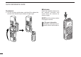
■ Your first scanning experience D Charging the battery IC-R20 Optional CP-18A/E Cigarette lighter cable with DC-DC converter to [DC] jack to cigarette lighter socket AC adaptor Turn power BC-149A/D OFF. to AC outlet Now that you have your IC-R20 ready, you are probably excited to start listening. We would like to take you through a few basic operation steps to make your first “Scanning Experience” enjoyable.
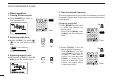
QUICK REFERENCE GUIDE D Basic operation 4. Tune the desired frequency 1. Turning ON the receiver The tuning dial will allow you to dial in the frequency you want to operate. Pages 9 and 15 will instruct you on how to set the tuning speed. ➥ Push [POWER] for 1 sec. to turn the power ON. -DUP TSQL MODE FM ANL AFC 146 010 DUALWATCH MAIN/SUB POWER BAND VFO MHz MODE SCAN MR S.
■ Memory programming The IC-R20 has a total of 1250 memory channels (including 200 auto write channels and 50 scan edges) for storing often used receive frequency, mode, etc. [Using the keypad] ➥ Enter the desired frequency via the keypad. • Direct input can be set until 1 kHz digit, rotate [R-DIAL] to set below 1 kHz frequency after set tuning steps, if necessary. (See p. 14 for setting the tuning step.) • Pushing [VFO MHz] omits the entry of 100 kHz and below, when you want to edit to these digits “0.
QUICK REFERENCE GUIDE ■ Programmed scan operation 25 pairs, 50 channels of memories are used for programmed scan operation, that specify a scanning range. The programmed scan scans between “xxA” and “xxB” (xx=00 to 24) frequencies. Therefore, before operating the programmed scan, different frequencies must be programmed into “A” and “B” channels. D Programming scan edges A start frequency must be programmed into a “xxA,” and end frequency must be programmed into a “xxB” memory channel. 1.
D Starting scan 1. Select VFO mode. 3. Starting scan Push [VFO MHz] to select the VFO mode for full, band and programmed scan operation. • Rotate [R-DIAL] to change the scanning direction. Release [MODE SCAN] to start the scan. • Select memory mode by pushing [MR S.MW] for memory or bank scan. 2. Selecting a scanning type While pushing and holding [MODE SCAN], rotate [R-DIAL] to select one of the desired scanning type.
1 PANEL DESCRIPTION ■ Front, top and side panels i q q ANTENNA CONNECTOR (p. II) BNC connector: Connects the supplied antenna. u y w t r e KEYPAD w SQUELCH KEY [SQL] (p. 18) ➥ Push and hold to temporarily open the squelch and monitor the operating frequency. ➥ While pushing this key, rotate the tuning dial* to adjust the squelch level. Y]/[Z Z] e UP/DOWN KEYS [Y Adjust audio volume level.* (p. 17) r USB JACK [USB] Connects to a PC using an optional OPC-1382 CLONING CABLE for cloning.
PANEL DESCRIPTION u LEFT DIAL [L-DIAL] ➥ During single band operation, rotate to adjust audio volume level.* (p. 17) ➥ During dualwatch operation, activates as the tuning dial for upper side on the display.* i RIGHT DIAL [R-DIAL] ➥ Rotate to select the operating frequency.* (p. 12) ➥ While scanning, changes the scanning direction.* (p. 26) ➥ While pushing [SQL], sets the squelch level.* (p. 18) ➥ While pushing [VFO MHz], sets the operating frequency in 1 MHz or 10 MHz in VFO mode.* (p.
1 PANEL DESCRIPTION t VFO/MHz KEY [VFO MHz] ➥ Push to select VFO mode. (p. 11) VFO MHz ➥ Push for 1 sec. to toggle between the 1 MHz or 10 MHz tuning steps (p. 14) y MODE/SCAN KEY [MODE SCAN] ➥ Push to select the operating mode (FM, WFM, MODE SCAN AM, USB, LSB, CW). (p. 16) ➥ Push for 1 sec. to start a scan. (p. 35) u MEMORY KEY [MR S.MW] ➥ Push to select between memory mode, TV MR S.MW channel and PreSet channel. (p. 11) ➥ Push for 1 sec. to enter memory write condition. (p. 26) ➥ Push for 2 sec.
PANEL DESCRIPTION !2 TONE SCAN KEY [4 T-SCAN] T SCAN ➥ Inputs digit ‘4’ for frequency input, memory channel selection, etc. ➥ Push for 1 sec. to start a tone scan. (p. 48) !3 FREQUENCY SKIP KEY [5 SKIP] SKIP ➥ Inputs digit ‘5’ for frequency input, memory channel selection, etc. ➥ Push for 1 sec. to turn the frequency skip function ON and OFF in VFO mode. (p. 39) • “PSKIP” appears when the frequency skip function is in use. ➥ Push for 1 sec.
1 PANEL DESCRIPTION !8 TUNING STEP KEY [9 TS] TS ➥ Inputs digit ‘9’ for frequency input, memory channel selection, etc. ➥ Push for 1 sec. to select the tuning step. (p. 14) !9 LOCK KEY [• LOCK] ➥ Inputs MHz digit for frequency input. (p. 15) LOCK ➥ Push for 1 sec. to toggle the lock function ON and OFF. (p. 16) •“ ” appears while the key lock function is in use. @0 REWIND/ATTENUATOR KEY [ΩΩ ATT] ATT ➥ Push to select the track for recorded audio. (p.
PANEL DESCRIPTION 1 ■ Function display q !5 !2 er -DUP TSQL MODE FM ANL t y M:Amateur2 √ PRI RIO PSKIP !4 t u i ATT !1 e 145 000 PS PRIO 000 q w o !5 !6 433 000 ➥“ ” appears when the batteries are nearing exhaustion. • IC-R20 installed the BP-206 must be charged presently, but when it installed alkaline batteries can be operate for a while. ➥ Scrolls while charging the installed BP-206. (p. 8) ➥ Battery indicator blinks when completely charged.
1 PANEL DESCRIPTION r ANL/NB INDICATOR (pgs. 21, 52) ➥ “ANL” appears when the ANL (Automatic Noise Limitter) function is in use. The ANL function is available only for AM mode. ➥ “NB” appears when the noise blanker function is in use. The noise blanker function is available while in LSB/USB/CW modes. o SIGNAL STRENGTH INDICATOR Shows the receiving signals relative to signal strength. t LOCK INDICATOR (p. 16) Appears when the lock function is activated. !2 VOLUME/DIAL EXCHANGE INDICATOR (p.
BATTERY INSTALLATION/CHARGING 2 ■ Battery installation Make sure receiver power is turned OFF before installing or replacing the batteries. qRemove the battery cover from the receiver. D Battery pack installation 1 2 q Remove the battery cover from the receiver. w Remove the supplied battery spacer for R6 (AA) size battery use. e Install the Li-Ion battery pack (BP-206). • Be sure to observe the correct direction. • Charge the Li-Ion battery pack before use.
2 BATTERY INSTALLATION/CHARGING ■ Caution D Battery caution CAUTION! NEVER short the battery terminals. Current will flow into metal objects, so be careful when placing battery pack in handbags, etc. NEVER incinerate used battery packs or battery cells. Internal battery gas may cause explosion. NEVER mix old and new batteries. Make sure all battery cells are the same brand, type and capacity. Either of the above may cause a fire hazard or damage the receiver if ignored.
BATTERY INSTALLATION/CHARGING 2 D CP-18A/E fuse replacement D Rapid charging with the BC-156 If the fuse blows or the receiver stops functioning while operating with the optional CP-18A/E, find the source of the problem if possible, and replace the damaged fuse with a new rated one (FGB 5 A) as shown below. The optional BC-156 provides rapid charging of battery pack (BP-206). 2 • Charging periods: 2.5 hours (w/BP-206) Shorten or remove the antenna. Turn power OFF.
3 FREQUENCY AND CHANNEL SETTING ■ Mode selection D VFO mode D Memory mode/PreSet*/TV*/Weather† channels VFO mode is used for the desired frequency setting within the frequency coverage. Memory mode is used for operation of memory channels which have programmed frequencies. PreSet channels are used for most-often used frequencies for quick recall. ➥ Push [VFO MHz] to select VFO mode. • VFO mode indication DUALWATCH MAIN/SUB POWER BAND VFO MHz MODE SCAN DIAL.
FREQUENCY AND CHANNEL SETTING 3 ■ Operating band selection • Memory mode indication -DUP TSQL MODE FM ANL AFC PSKIP µ 001 “µ ” and memory channel number appear. • PreSet channel indication -DUP TSQL MODE WFMANL AFC 76 000 √ -DUP TSQL MODE WFMANL AFC 2 ch 146 100 √ • TV channel indication 3 ➥ In VFO mode, push [BAND] several times to select the desired frequency band.
3 FREQUENCY AND CHANNEL SETTING • Available frequency bands MODE AM 1620 AM broadcast band MODE MODE AM 5 000 HF band FM 51 000 50 MHz band MODE FM broadcast band MODE : Push MODE AM 118 000 BAND VHF air band FM 2425 000 2400 MHz band WFM 76 000 : Rotating while pushing BAND Initial frequencies shown will differ according to version.
FREQUENCY AND CHANNEL SETTING ■ Setting a tuning step ■ Setting a frequency The tuning step can be selected for each frequency band independently, however, the tuning steps, 8.33 kHz and 9 kHz, only appear when setting the tuning step for the VHF air band and AM broadcast band, respectively. The following tuning steps are available for the IC-R20. • 0.01 kHz • 0.1 kHz • 1.0 kHz • 5.0 kHz • 6.25 kHz • 8.33 kHz* • 9.0 kHz* • 10.0 kHz • 12.5 kHz • 15.0 kHz • 20.0 kHz • 25.0 kHz • 30.0 kHz • 50.0 kHz • 100.
3 FREQUENCY AND CHANNEL SETTING D Using the keypad The frequency can be directly set via numeral keys. • When editing a frequency outside of the frequency range, the previously displayed frequency is automatically recalled after editing last digit. qPush [VFO MHz] to select VFO mode, if necessary. w Enter the desired frequency via the keypad. • Direct input can be set until 1 kHz digit, rotate [R-DIAL] to set below 1 kHz frequency after set tuning steps, if necessary.
FREQUENCY AND CHANNEL SETTING 3 ■ Receive mode selection ■ Lock function Receive modes are determined by the physical properties of the radio signals. The receiver has 6 receive modes: FM, WFM, AM, LSB, USB and CW modes. The mode selection is stored independently in each band and memory channels. To prevent accidental frequency changes and unnecessary function access, use the lock function. Typically, AM mode is used for the AM broadcast stations (0.495–1.620 MHz) and VHF air band (118–135.
4 BASIC OPERATION ■ Receiving ■ Setting audio volume Make sure charged battery pack (BP-206) or brand new alkaline batteries are installed (p. 8). The audio level can be adjusted through 39 levels. q Push [POWER] for 1 sec. to turn power ON. Y] or [Z Z]) to set the desired wRotate [L-DIAL] (or push [Y audio level. • The frequency display shows the volume level while setting. See the section at right for details. e Set the receiving frequency. (p. 14) r Set the squelch level. (p.
BASIC OPERATION 4 ■ Squelch level setting ■ Monitor function The squelch circuit mutes the received audio signal depending on the signal strength. The receiver has 9 squelch levels, a continuously open setting and an automatic squelch setting. This function is used to listen to weak signals without disturbing the squelch setting or to open the squelch manually even when mute functions such as the tone squelch are in use. ➥ While pushing and holding [SQL], rotate [R-DIAL] to select the squelch level.
4 BASIC OPERATION ■ Attenuator function ■ RF gain The attenuator prevents a desired signal from distorting when very strong signals are near the desired frequency or when very strong electric fields, such as from a broadcasting station, are near your location. The attenuator gain is about 30 dB. The receiver gain can be reduced with the RF gain setting. This may help to remove undesired weak signals while monitoring strong signals.
BASIC OPERATION ■ Duplex operation Duplex communication uses 2 different frequencies for transmitting and receiving. Generally, duplex is used in communication through a repeater, some utility communications, etc. During duplex operation, the transmit station frequency is shifted from the receive station frequency by the offset frequency. Repeater information (offset frequency and shift direction) can be programmed into memory channels. (p.
4 BASIC OPERATION ■ AFC function ■ NB/ANL function The AFC (Automatic Frequency Control) function tunes the displayed frequency automatically when an off-center frequency is received. It activates in FM/WFM modes only with single band operation. The NB (noise blanker) function removes pulse-type noise when USB, LSB or CW mode is selected. The ANL (Automatic Noise Limitter) function reduces noise components when AM mode is selected. ➥ Push [0 AFC] to toggle the AFC function ON and OFF.
BASIC OPERATION 4 ■ Band scope The band scope function allows you to visually check a specified frequency range. Sweep range can be selected from ±14 kHz through ±1400 kHz. q Set the desired frequency as band scope center frequency. w While pushing and holding [2 SWEEP], rotate [R-DIAL] to select the sweep steps, if desired. • Available steps are 1, 5, 6.25, 8.33, 9, 10, 12.5, 15, 20, 25, 30, 50 and 100 kHz. • Pushing [2 SWEEP] changes the sweep step and starts single sweeping at each times.
4 BASIC OPERATION ■ [DIAL] function assignment The frequency control dial can be traded with an audio volume Y]/[Z Z] keys to suit your preference. control dial or [Y ➥ Push [1 DIAL.SEL] for 1 sec. to toggle the dial function from tuning dial and audio volume.
5 DUALWATCH OPERATION ■ Main band selection ■ Band exchange ➥ Push [MAIN/SUB] momentarily to select the upper band or lower band as main band (operating band) alternately. ➥ Push [MAIN/SUB] for 1 sec to exchange the upper band’s frequency and lower band’s frequency.
5 DUALWATCH OPERATION ■ Setting audio volume ■ Squelch level setting qPush [DUALWATCH] for 1 sec. to enter the dualwatch operation, if necessary Y] or [Z Z] to adjust the audio wPush and hold [SQL], push [Y level for the main band. qPush [DUALWATCH] for 1 sec. to enter the dualwatch operation, if necessary wWhile pushing and holding [SQL], rotate [L-DIAL] for upper band’s squelch adjustment, or rotate [R-DIAL] for lower band’s squelch adjustment.
6 MEMORY CHANNELS ■ General description ■ Memory channel programming The receiver has 1050 memory channels including 50 scan edge memory channels (25 pairs) for storage of often-used frequencies. And a total of 26 memory banks, A to Z are available for usage by group, etc. Up to 100 channels can be assigned into a bank. q Push [VFO MHz] to select VFO mode. w Set the desired frequency: ➥ Select the desired band with [BAND]. ➥ Set the desired frequency with [R-DIAL].
6 MEMORY CHANNELS ■ Memory bank setting The IC-R20 has a total of 26 banks (A to Z). Regular memory channels, 000 to 999, are assigned into the desired bank for easy memory management. qPush [MR S.MW] for 1 sec. to select the select memory write condition. • 1 short and 1 long beep sound. µ ” indicator blinks. • “µ w Rotate [R-DIAL] to select the desired memory channel. eWhile pushing [8 SET], rotate [R-DIAL] to select “BANK.” • “BANK” item can also be selected by pushing [8 SET] several times.
MEMORY CHANNELS 6 ■ Memory bank selection q Push [MR S.MW] to select memory mode. wWhile pushing [BAND], rotate [R-DIAL] to select the desired bank (A to Z). • The bank can also be selected by pushing [BAND] several times. • Only programmed banks are displayed. -DUP TSQL MODE FM ANL AFC 145 870 [R-DIAL] PSKIP µ 001 √ ATT Rotate [R-DIAL] while pushing [BAND] BAND MR S.MW -DUP TSQL MODE AM ANL eRotate [R-DIAL] to select the bank channel. • Only programmed channels are displayed.
6 MEMORY CHANNELS ■ Programming memory/bank name Each memory channel can be programmed with an alphanumeric channel name for easy recognition and can be indicated independently by channel. Names can be a maximum of 8 characters. q Push [MR S.MW] to select memory mode. w Rotate [R-DIAL] to select the desired memory channel. ePush [MR S.MW] for 1 sec. to select the select memory write condition. • 1 short and 1 long beep sound. µ ” indicator blinks.
MEMORY CHANNELS D Available characters A B C D E F G H I J K L M N O P Q R S T U V W X Y Z a b c d e f g h i j k l m n o p ■ Selecting memory/bank name indication During memory mode operation, one of the programmed memory name or bank name can be displayed below the frequency indication. -DUP TSQL MODE FM ANL q r s t u v w x y z 0 1 2 3 4 5 6 7 8 9 6 145 700 [R-DIAL] B:GROUP1 6 PSKIP µ 012 √ ‰ Ò ¨ Î ! " # $ % & ' ( ) * + , AFC ATT - .
6 MEMORY CHANNELS ■ Copying memory contents Pushing [MR S.MW] for 2 sec. at the step w, will also copy the memory contents to VFO. In this case, the steps e and r are not necessary. This function transfers a memory channel’s contents to VFO (or another memory channel). This is useful when searching for signals around a memory channel frequency and for recalling the offset frequency, subaudible tone frequency etc. D Memory➪VFO D Memory➪memory q Select the memory channel to be copied. ➥ Push [MR S.
MEMORY CHANNELS 6 ■ Memory clearing Contents of programmed memories can be cleared (blanked), if desired. qPush [MR S.MW] for 1 sec. to select the select memory write condition. • 1 short and 1 long beeps sound. µ ” indicator blinks. • “µ • Do not hold [MR S.MW] for more than 2 sec. otherwise the memory contents will be copied to VFO. wRotate [R-DIAL] to select the desired memory channel to be cleared. eWhile pushing [8 SET], rotate [R-DIAL] to select “CLEAR.
6 MEMORY CHANNELS ■ Erasing/transferring bank contents The bank contents of programmed memory channels can be cleared or reassigned to another memory bank. INFORMATION: Even if the memory bank contents are cleared, the memory channel contents still remain programmed. qSelect the desired bank contents to be transferred or erased from the bank. ➥ Push [MR S.MW] to select memory mode. ➥ While pushing [BAND], rotate [R-DIAL] to select the desired memory bank group.
SCAN OPERATION 7 ■ Scan types Scanning searches for signals automatically and makes it easier to locate new stations for contact or listening purposes. FULL SCAN (p. 35) 150 kHz 3304.999 MHz Scan Jump PROGRAMMED SCAN (p. 37) Band edge Scan edges Band xxB edge xxA Scan Jump SKIP A01 Some frequency ranges are not scanned according to the frequency coverage of the receiver’s version. Repeatedly scans between two user-programmed frequencies.
7 SCAN OPERATION ■ Full/band/programmed scan q Select VFO mode with [VFO MHz]. r To start the scan, release [MODE SCAN]. • Select the desired frequency band with [BAND], if desired. w Set the squelch level. eWhile pushing and holding [MODE SCAN], rotate [R-DIAL] to select the desired scanning type. • “ALL” for full scan; “BAND” for band scan, “PROG-xx” for programmed scan (xx= 0 to 24; programmed scan edges numbers only displayed) • Scan pauses when a signal is received.
SCAN OPERATION 7 ■ Scan edges programming Scan edges can be programmed in the same manner as memory channels. Scan edges are programmed into scan edges, 00A/00B to 24A/24B, in memory channels. t Push [MR S.MW] for 1 sec. q Push [VFO MHz] to select VFO mode. w Set the desired frequency: ➥ Select the desired band with [BAND]. ➥ Set the desired frequency with [R-DIAL]. ➥ Set other data (e.g. offset frequency, duplex direction, tone squelch, etc.), if desired. ePush [MR S.MW] for 1 sec.
7 SCAN OPERATION ■ Memory/bank/all bank scan q Select memory mode with [MR S.MW]. r Release [MODE SCAN] to start the selected scan. • Select the desired bank with [BAND] for bank scan. w Set the squelch level. eWhile pushing and holding [MODE SCAN], rotate [R-DIAL] to select the desired scanning type. • “ALL” for all bank scan; “BANK-LINK” for bank link scan or “BANK-x” for bank scan. (x= A to Z; programmed bank groups only displayed.) • Full memory scan selection [R-DIAL] -DUP TSQL MODE FM ANL MR S.
SCAN OPERATION ■ Auto-memory write scan This scan is useful for searching a specified frequency range and automatically storing busy frequencies into memory channels. The auto-memory write scan is performed with any VFO scan types (ALL, BAND, PROG). q Select VFO mode with [VFO MHz]. wPush and hold [MODE SCAN] to enter scanning type selection condition. e Rotate [R-DIAL] to select the desired scanning type.
7 SCAN OPERATION ■ Skip channel/frequency setting Memory channels can be set to be skipped for memory skip scan. In addition, memory channels can be set to be skipped for both memory skip scan and frequency skip scan. These are useful to speed up the scan interval. q Select a memory channel: ➥ Push [MR S.MW] to select memory mode. ➥ Rotate [R-DIAL] to select the desired channel to be a skip channel/frequency. wPush [MR S.MW] for 1 sec. to enter the select memory write condition.
SCAN OPERATION ■ Scan resume condition IN 7 EXPANDED SET MODE D Scan pause timer The scan pauses when receiving signals according to the scan pause time. It can be set from 2 to 20 sec. or unlimited. q Push [8 SET] for 1 sec. to enter set mode. wRotate [R-DIAL] to select “SET EXPAND,” then push [8 SET]. eRotate [R-DIAL] to turn the expand set mode selection ON, then push [8 SET]. rRotate [R-DIAL] to select “SCAN PAUSE,” then push [8 SET].
7 SCAN OPERATION D Scan resume timer The scan restarts after the signal disappears according to the resume time. It can be set from 0–5 sec. or unlimited. q Push [8 SET] for 1 sec. to enter set mode. wRotate [R-DIAL] to select “SET EXPAND,” then push [8 SET]. eRotate [R-DIAL] to turn the expand set mode selection ON, then push [8 SET]. rRotate [R-DIAL] to select “SCAN RESUME,” then push [8 SET]. tRotate [R-DIAL] to set the desired scan resume timer from 0–5 sec. (1 sec. steps) and “HOLD.
PRIORITY WATCH 8 ■ Priority watch types Priority watch checks for signals on the frequency every 5 sec. while operating on a VFO frequency or scanning. The receiver has 3 priority watch types to suit your needs. The watch resumes according to the selected scan resume condition. See the left page for details. NOTE: If the pocket beep function is activated, the receiver automatically selects the tone squelch function when priority watch starts.
8 PRIORITY WATCH ■ Priority watch operation D Memory channel watch and memory scan watch q Select VFO mode; then, set an operating frequency. w Set the watching channel(s). For memory channel watch: Select the desired memory channel. For memory scan watch: Select memory mode, or the desired bank group; then, push [MODE SCAN] for 1 sec. to start memory/bank scan. e Push [8 SET] for 1 sec. to enter set mode. rRotate [R-DIAL] to select “PRIORITY WATCH,” then push [8 SET].
PRIORITY WATCH 8 D VFO scan watch q Select memory mode. • Select a memory bank, if desired. wPush [MODE SCAN] for 1 sec. to start memory/bank scan, if desired. While scanning memory/bank channels: Starts memory/bank scan first. Memory/bank scan cannot be started after VFO scan is started. e Push [8 SET] for 1 sec. to enter set mode. r Rotate [R-DIAL] to select “PRIO,” then push [8 SET]. t Rotate to turn the priority watch ON, then push [8 SET]. • Select “BELL” if the priority beep function is necessary.
9 COMFORTABLE RECEIVING ■ Tone/DTCS squelch operation The tone or DTCS squelch opens only when receiving a signal with the same pre-programmed subaudible tone or DTCS code, respectively. You can silently wait for the specified signal using the same tone. q Set the desired frequency in FM mode. wWhile pushing [7 TONE], rotate [R-DIAL] to select the desired squelch condition from “TSQL,” “TSQLS,” “DTCS,” “DTCSS,” “VSC” and “OFF.
COMFORTABLE RECEIVING 9 ■ Tone squelch frequency/DTCS code setting 88.5 Hz and 023 is set as the default for the tone squelch frequency and the DTCS code, respectively. The frequency and code can be selected as desired. q Push [8 SET] for 1 sec. to enter set mode. wRotate [R-DIAL] to select “SET EXPAND,” then push [8 SET]. eRotate [R-DIAL] to turn the expanded set mode ON, then push [8 SET].
9 COMFORTABLE RECEIVING ■ DTCS polarity setting As well as the code setting, the polarity setting is also available for the DTCS operation. When a different polarity is set, the DTCS never releases audio mute even when a signal with matched code number is received. q Push [8 SET] for 1 sec. to enter set mode. wRotate [R-DIAL] to select “SET EXPAND,” then push [8 SET]. eRotate [R-DIAL] to turn the expanded set mode ON, then push [8 SET]. rRotate [R-DIAL] to select “DTCS POLARITY,” then push [8 SET].
COMFORTABLE RECEIVING 9 ■ Tone scan By monitoring a signal that is being operated with pocket beep, tone or DTCS squelch function, you can determine the tone frequency or DTCS code necessary to open a squelch. qSet the frequency to be checked for a tone frequency or code. wTurn the desired tone type, tone squelch or DTCS, ON by holding [7 TONE] with turning [R-DIAL]. • One of “TSQL” or “DTCS” appears. • Even when the pocket beep function is activated, the function is cancelled when starts the tone scan.
10 SET MODE ■ General Set mode is used for programming infrequently changed values or conditions of functions. In addition, the IC-R20 has an expanded set mode which is used for programming even more infrequently changed values or conditions of functions. When turning the expanded set mode OFF, only about one third of the set mode items are displayed for simple operation. D Set mode entering and operation q Push [8 SET] for 1 sec. to enter set mode.
SET MODE ■ Set mode items D Expanded set mode items The following items are available in the set mode and expanded set mode. ***-SET-MODE-*** ----------------LOCK -DIAL-SPEED-UP -MONITOR -AUTO-POWER-OFF >SCAN-PAUSE -SCAN-RESUME D General set mode items ***-SET-MODE-*** --------------->PRIORITY-WATCH -KEY-TOUCH-BEEP -BEEP-LEVEL -BACKLIGHT -POWER-SAVE -NOISE-BLANKER • Priority watch (p. 51) • Key-touch beep (p. 51) • Beep output level (p. 51) • Display backlighting (p. 51) • Power save (p.
10 SET MODE D Priority watch D Beep output level Turn the priority watch or priority beep (priority watch with beep emission capability) ON. (default: OFF) • ON : Start priority watch after exiting set mode. • BELL : Emits beeps and blinking “S” indicator when a signal is received on the priority frequency. Adjust the key-touch beep tone level to the desired level within 39 levels. The key-touch beep (previous item) must be set to ON to have a beep tone.
SET MODE 10 D Power save D ANL function The power save function reduces the current drain to conserve battery power. This power save function can be turned OFF, if desired. In the default setting (“AUTO” selection), the power save function is activated in 1:4 (125 msec.: 500 msec.) ratio when no signal is received for 5 sec. The ratio becomes 1:8 (125 msec.: 1 sec.) when no signal is received for another 60 sec. The ANL (Automatic Noise Limitter) function reduces noise components when AM is selected.
10 SET MODE D Key lock effect D AM antenna selection This setting is activated only for the AM broadcast band, 0.495–1.620 MHz (differ according to version) reception. • EXT : Use the antenna connected to the antenna connector. (default) • BAR : Use the internal bar antenna for AM broadcast band reception. AM-ANTENNA ----------------EXT >BAR AM-ANTENNA --------------->EXT -BAR External antenna Internal bar antenna D FM antenna selection This setting is activated only for the FM broadcast band, 76.
SET MODE 10 D Dial speed acceleration D Auto power OFF The dial speed acceleration automatically speeds up the tuning dial speed when rotating [R-DIAL] rapidly. • OFF : The dial speed acceleration is turned OFF. • ON : The dial speed acceleration is tuned ON. (default) The receiver can be set to automatically turn OFF after a specified period has past.
10 SET MODE D Scan pause timer D Scan resume timer Selects the scan pause time. When receiving signals, the scan pauses according to the scan pause time. • 2–20 : Scan pauses for 2–20 sec. on a received signal, and selected in 2 sec. steps. (default: 10 sec.) • HOLD : Scan pauses on a received signal until it disappears. Rotate [R-DIAL] to resume manually. Selects scan resume time. Scan resumes after the specified period when the received signal disappears.
SET MODE 10 D Scope audio output D Duplex direction Sets the audio output function while scope operation. Sets the duplex direction. The displaying frequency shifts the programmed offset frequency (at left below) when monitor function is in use (while pushing [SQL]). • OFF : Simplex operation. (default) • –DUP : The displaying frequency shifts down during monitor. • +DUP : The displaying frequency shifts up during monitor.
10 SET MODE D Tone frequency • Available DTCS code Sets subaudible tone frequency for tone squelch operation. Total of 50 tone frequencies (67.0–254.1 Hz) are available. (default: 88.5 Hz) TONE-FREQ -----------------88.5 TONE-FREQ ---------------254.1 88.5 Hz setting 254.1 Hz setting 79.7 82.5 85.4 88.5 91.5 94.8 97.4 100.0 103.5 107.2 110.9 114.8 118.8 123.0 127.3 131.8 136.5 141.3 146.2 151.4 156.7 159.8 162.2 165.5 167.9 171.3 173.8 177.3 179.9 183.5 186.2 189.9 192.8 196.6 199.5 203.
SET MODE D Memory bank link D LCD contrast Sets the linked bank for the bank-link scan. (default: All banks are ON) qRotate [R-DIAL] to select the bank that you want to change setting. The LCD contrast can be adjusted through 15 levels. Minimum level BANK-LINK --------------->BANK-A:ON -BANK-B:ON -BANK-C:ON -BANK-D:ON -BANK-E:ON -BANK-F:ON When OFF is selected LCD-CONTRAST Maximum level D Weather alert function U.S.A. version only Turns weather alert function ON and OFF. wPush [8 SET] for 1 sec.
10 SET MODE D CI-V address D CI-V transceive To distinguish equipment, each CI-V transceiver/receiver has its own Icom standard address in hexadecimal code. The ICR20’s address is “6C.” CI-V transceive operation is possible with the IC-R20 connected to an Icom CI-V radio. When “ON” is selected, changing the frequency, operating mode, etc. on the IC-R20 automatically changes those of connected radios and vice versa.
OTHER FUNCTIONS 11 ■ Antenna selection The IC-R20 has an internal bar antenna installed for receiving AM broadcast band (0.495–1.620 MHz; differ according to version) signals. In addition, the connected earphone’s cable can be used as an antenna for receiving FM broadcast band (76.000–107.995 MHz; differ according to version) signals. D Selecting antenna q Push [8 SET] for 1 sec. to enter set mode.
11 OTHER FUNCTIONS ■ Weather channel operation U.S.A. version only D Weather channel selection qPush [MR S.MW] several times to select the weather channel group. w Rotate [R-DIAL] to select the desired weather channel. [R-DIAL] Weather channel indication -DUP TSQL MODE FM ANL VFO MHz AFC 1 √ PSKIP WX MR S.MW ePush [VFO MHz] to return to VFO mode, or push [MR S.MW] to select other mode to exit the weather channel.
OTHER FUNCTIONS 11 ■ Data cloning Cloning allows you to quickly and easily transfer the programmed contents from a personal computer to a receiver using the optional CS-R20 CLONING SOFTWARE. • The receiver shows following indications. Write to receiver CLONE-IN CLONE During cloning After cloning D Cloning using a personal computer Data can be cloned to and from a personal computer (Microsoft® Windows® 98/Me/2000/XP) using the optional CSR20 CLONING SOFTWARE and the optional OPC-1382 CLONING CABLE.
11 OTHER FUNCTIONS ■ Auto power-off function D Cloning error NOTE: DO NOT push any key on the receiver during cloning. This will cause a cloning error. When the display appears as below, a cloning error has occurred. In such a case, the receiver automatically performs ALL RESET while turning power OFF and ON. CLONE-ERROR IN EXPANDED SET MODE The IC-R20 can be set to automatically turn OFF after a specified period in which no operation is performed. BUSY, 120 min., 90 min., 60 min., 30 min.
OTHER FUNCTIONS ■ IC recorder D Playing back recorded content qPush [ΩΩ ATT]/[≈≈ RF GAIN] to select the desired track. The IC-R20 has an IC recorder of up to 32 tracks. The maximum recording length is about 260 minutes. • The track number appears. ATT RF GAIN IC Recorder D Recording a received audio -DUP TSQL MODE FM ANL PSKIP • Red LED below the [ REC] lights ON. wPush [ REC] to pause to record or push [■ ≈] to stop recording. • While pausing the red LED blinks.
11 OTHER FUNCTIONS • Playback speed setting The playback speed can be selected from 5 speeds. qPush [■ ≈] for 1 sec. to enter the playback speed set mode. wRotate [R-DIAL] to select the desired playback speed, then push [■ ≈]. • x0.50 : Playback the recorded content at half speed. • x0.75 : Playback the recorded content at three quarters speed. • x1.00 : Playback the recorded content at normal speed. (default) • x1.25 : Playback the recorded content at 1.25 times speed. • x1.
OTHER FUNCTIONS • Automatic recording • Erasing recorded audio The IC-R20 has an automatic recording function. When this function is activated, the receiver will record automatically when a receiving signal appears and pause when the signal disappears. This function is very useful when you want to store an uncontinuous signal. qPush [ REC] for 1 sec. to enter the recording set mode. wRotate [R-DIAL] to select “REC REMOTE,” then push [ REC].
11 OTHER FUNCTIONS ■ Partial reset AT POWER ON If you want to initialize the operating conditions (VFO frequency, VFO settings, set mode contents) without clearing the memory contents, a partial resetting function is available for the receiver. ➥ While pushing [VFO MHz], turn the power ON to partially reset the receiver. ■ All reset AT POWER ON The function display may occasionally display erroneous information (e.g. when first applying power).
CONTROL COMMAND ■ General The IC-R20 can be connected to a PC via the PC’s RS-232C port using an optional CT-17 CI-V LEVEL CONVERTOR. This allows you to control the receiver from the PC and/or transfer data from the receiver to the PC. Control is provided via Icom’s CI-V Communication Interface. An appropriate application for CI-V command is not supplied from Icom.
12 CONTROL COMMAND CI-V connections example CI-V compatible transceiver Power supply 9–15VDC Computer Optional BC-25 CI-V compatible transceiver RS-232C cable CT-17 IC-R20 to [SP/CI-V] 2-conductor 3.5(d) mm plug 3-conductor 3.5(d) mm plug must be used. GND GND 3.
FREQUENCY TABLE ■ TV channels D CCIR channels Following tables show the channels versus video and audio frequencies depending on each version. D U.S.A. channels (unit: MHz) CH 2 3 4 5 6 7 8 9 10 11 12 13 14 15 16 17 18 19 20 21 22 23 24 25 26 Freq. 59.75 65.75 71.75 81.75 87.75 179.75 185.75 191.75 197.75 203.75 209.75 215.75 475.75 481.75 487.75 493.75 499.75 505.75 511.75 517.75 523.75 529.75 535.75 541.75 547.75 CH 27 28 29 30 31 32 33 34 35 36 37 38 39 40 41 42 43 44 45 46 47 48 49 50 51 Freq. 553.
13 FREQUENCY TABLE D China channels CH 1 2 3 4 5 6 7 8 9 10 11 12 13 14 15 16 17 18 19 20 21 22 23 24 25 26 27 28 29 30 31 71 Freq. 56.25 64.25 72.25 83.75 91.75 174.75 182.75 190.75 198.75 206.75 214.75 222.75 477.75 485.75 493.75 501.75 509.75 517.75 525.75 533.75 541.75 549.75 557.75 565.75 613.75 621.75 629.75 637.75 645.75 653.75 661.75 CH 32 33 34 35 36 37 38 39 40 41 42 43 44 45 46 47 48 49 50 51 52 53 54 55 56 57 58 59 60 61 62 (unit: MHz) Freq. 669.75 677.75 685.75 693.75 701.75 709.75 717.
FREQUENCY TABLE D Indonesian channels (unit: MHz) CH 1A 2 3 4 5 6 7 8 9 10 11 21 22 23 24 25 26 27 28 29 30 31 32 33 34 35 36 37 38 39 Freq. 53.75 60.75 67.75 180.75 187.75 194.75 201.75 208.75 215.75 222.75 229.75 476.75 484.75 492.75 500.75 508.75 516.75 524.75 532.75 540.75 548.75 556.75 564.75 572.75 580.75 588.75 596.75 604.75 612.75 620.75 CH 40 41 42 43 44 45 46 47 48 49 50 51 52 53 54 55 56 57 58 59 60 61 62 63 64 65 66 67 68 69 Freq. 628.75 636.75 644.75 652.75 660.75 668.75 676.75 684.75 692.
13 FREQUENCY TABLE ■ VHF marine channels 73 (unit: MHz) CH Ship Ship No. Transmit Receive CH Ship Ship No. Transmit Receive CH Ship Ship No. Transmit Receive 01 01A 02 03 03A 04 04A 05 05A 06 07 07A 08 09 10 11 12 13 14 15 16 17 18 18A 19 19A 20 20A 21 21A 21b 22 22A 23 23A 24 25 25b 26 27 28 28b 60 61 61A 62 62A 63 63A 64 64A 65 65A 66 66A 67 68 69 70 71 72 73 74 77 78 78A 79 79A 80 80A 81 81A 82 82A 83 83A 83b 84 84A 85 85A 86 86A 87 87A 88 88A 156.050 156.050 156.100 156.150 156.150 156.
FREQUENCY TABLE 13 ■ Other communications in the USA D HF CB (Citizens Band) channels CH 1 2 3 4 5 6 7 8 9 10 11 12 13 14 15 16 17 18 19 20 Frequency 26.965 MHz 26.975 MHz 26.985 MHz 27.005 MHz 27.015 MHz 27.025 MHz 27.035 MHz 27.055 MHz 27.065 MHz 27.075 MHz 27.085 MHz 27.105 MHz 27.115 MHz 27.125 MHz 27.135 MHz 27.155 MHz 27.165 MHz 27.175 MHz 27.185 MHz 27.205 MHz D MURS channels CH 1 2 3 4 5 Frequency 151.820 MHz 151.880 MHz 151.940 MHz 154.570 MHz 154.
13 FREQUENCY TABLE D General aviation frequencies Frequency 121.500 122.000 122.200 122.700 122.725 122.750 122.800 122.900 122.950 123.000 123.025 123.050 123.075 123.100 123.300 123.450 123.500 123.600 148.125 148.150 156.300 156.400 156.425 156.450 156.625 156.900 243.000 255.400 257.800 311.000 321.000 381.
FREQUENCY TABLE 13 ■ Other communications— other countries D LPD (Low Power Device) channels CH 1 2 3 4 5 6 7 8 9 10 11 12 13 14 15 16 17 18 19 20 21 22 23 24 25 26 27 28 29 Frequency 433.075 433.100 433.125 433.150 433.175 433.200 433.225 433.250 433.275 433.300 433.325 433.350 433.375 433.400 433.425 433.450 433.475 433.500 433.525 433.550 433.575 433.600 433.625 433.650 433.675 433.700 433.725 433.750 433.
13 FREQUENCY TABLE D UHF C.R.S (Citizen Radio Service) channels CH 1 2 3 4 5 6 7 8 9 10 11 12 13 14 15 16 17 18 19 20 77 Frequency 476.425 MHz 476.450 MHz 476.475 MHz 476.500 MHz 476.525 MHz 476.550 MHz 476.575 MHz 476.600 MHz 476.625 MHz 476.650 MHz 476.675 MHz 476.700 MHz 476.725 MHz 476.750 MHz 476.775 MHz 476.800 MHz 476.825 MHz 476.850 MHz 476.875 MHz 476.900 MHz CH 21 22 23 24 25 26 27 28 29 30 31 32 33 34 35 36 37 38 39 40 Frequency 476.925 MHz 476.950 MHz 476.975 MHz 477.000 MHz 477.
MAINTENANCE ■ Troubleshooting PROBLEM No power comes on. 14 If your receiver seems to be malfunctioning, please check the following points before sending it to a service center. POSSIBLE CAUSE • The batteries are exhausted. • The battery polarity is reversed. No sound comes from the • Volume level is too low. speaker. • Squelch level is set too tight. • Different tone is selected with tone squelch. SOLUTION • Replace the batteries or charge the battery pack. • Check the battery polarity. REF. pgs.
15 SPECIFICATIONS D GENERAL • Frequency coverage USA D RECEIVER : (Unit: MHz) 0.150–821.999, 851.000–866.999, 896.000–1304.999, 1305.000–3304.999 France 0.150–29.999, 50.200–51.200, 87.500–108.000, 144.000–146.000, 430.000–440.000, 1240.000–1300.000 Other than above 0.150–1304.999, 1305.000–3304.999 • Number of memory channels : 1250 (incl. 50 scan edges and 200 auto write channels) • Receive modes : FM, AM, WFM, USB, LSB, CW • Frequency resolution : 0.01, 0.1, 1, 5, 6.25, *8.33,*9, 10, 12.
OPTIONS 16 ■ Options BC-149 A/D AC ADAPTOR CP-18A/E CIGARETTE LIGHTER SP-13 EARPHONE CABLE WITH DC-DC CONVERTER Regularly charges the installed battery pack (BP-206). 6 V DC/1 A output. Same as supplied one. (Not supplied with some versions.) LC-158 CARRYING CASE Helps protect the receiver from scratches, etc. CT-17 CI-V LEVEL CONVERTOR For receiver remote control using a PC.
17 DRIVER INSTALLATION Before installing the optional CS-R20 CLONING SOFTWARE, the USB driver must be installed. Install the USB driver as follows. w The “Found New Hardware Wizard” will come up as below. • Insert the supplied CD into the CD drive, select “Install from a list or specific location (Advanced),” then click [Next>]. ■ For Microsoft® Windows® XP q Connect the IC-R20 to the desired USB port using with the USB cable, OPC-1382. • “Found New Hardware” appears as below.
DRIVER INSTALLATION eClick “Search for the best device in these locations,” click “Include the location in the search,” click [Browse] to select the CD drive. 17 rThe wizard starts searching for the driver and shows the dialog below during search.
17 DRIVER INSTALLATION tAfter the driver is found the “Hardware Installation” dialog box appears as below. • Click [Continue Anyway] to start the installation. Click 83 y Windows starts installing the USB driver.
DRIVER INSTALLATION uAfter the installation is completed, click [Finish]. 17 iThe “Found New Hardware Wizard,” will come up again to install the USB serial port driver. o “Hardware Update Wizard” appears as below. Select “Install from a list or specific location (Advanced)” then click [Next>]. Click Click 17 !0 Repeat step e to y.
17 DRIVER INSTALLATION !1 The following screen appears when the installation is completed. Click [Finish] to close the screen. ■ For Microsoft® Windows® 2000 q Connect the IC-R20 to the desired USB port using with the USB cable, OPC-1382. • “Found New Hardware” appears as below. w The “Found New Hardware Wizard” will come up as below. Click [Next>]. Click !2 After clicking [Finish], the dialog appears as below. • Rebooting the PC is recommended.
DRIVER INSTALLATION eSelect “Search for a suitable driver for my device (recommended),” then click [Next>]. 17 rSelect “CD-ROM drives,” and insert the supplied CD into the CD drive, then click [Next>].
17 DRIVER INSTALLATION tWhen the driver is found, the following dialog is displayed. Click [Next>] to start the installation. y After the installation is completed, click [Finish].
DRIVER INSTALLATION uThe “Found New Hardware Wizard,” will come up again to install the USB serial port driver. • “Found New Hardware” appears as below. 17 ■ For Microsoft® Windows® 98/98SE/Me q Connect the IC-R20 to the desired USB port using with the USB cable, OPC-1382. w The “Add New Hardware Wizard” will come up as below. Click [Next>]. iRepeat step w to t. oThe following screen appears when the installation is completed. Click [Finish] to close the screen.
17 DRIVER INSTALLATION eSelect “Search for the best driver for your device. (Recommended),” then click [Next>]. rSelect “Specify a location,” and insert the supplied CD into the CD drive, click [Browse] to select the CD drive, then click [Next>].
DRIVER INSTALLATION tWhen the driver is found, the following dialog is displayed. Click [Next>] to start the installation. 17 ■ COM port confirmation After the driver installation, confirm the driver availability and the port number are recommended. In this section, screen shots of Windows XP are used for instruction example. However, the instructions are similar to another operating systems, Windows 98, Me and 2000. q Boot up the Windows. w Select the “Control Panel” in the Start menu.
17 DRIVER INSTALLATION t Click the [Device Manager]. yClick “ ” of the “Ports (COM & LPT)” to display the usable COM port and the port number. Click Click • Device Manager screen appears as below. uConfirm the USB serial port availability and the COM port number. Confirm the USB serial port availability and the COM port number. (In this example, the USB serial port number is “3.”) iClose the Device Manager, System Properties screen and then Control panel.
92 iR20 ■ Squelch level setting ➥ While pushing [SQL], rotate [RDIAL] to set the squelch level. ■ Audio level setting ➥ Rotate [L-DIAL] (or push [Y]/ [Z]) to set the audio level. e Complete • “ATT” appears when the attenuator is in use. ■ Attenuator function ➥ Push [ΩΩ ATT] to toggle the attenuator ON and OFF. •“ ” appears when the lock function is in use. ■ Single band and dualwatch selection ➥ Push [DUALWATCH] for 1 sec. to toggle between single band and dualwatch operation.
■ Memory channel programming q Set the desired frequency and other functions in VFO mode. w Push [MR S.MW] for 1 sec. to enter the select memory write condition. • 1 short and 1 long beeps sound. e Rotate [R-DIAL] to select the desired memory channel number. r Push [MR S.MW] for 1 sec. again to program the contents into the selected channel. • 3 beeps sound. ■ Scan skip setting q Push [MR S.MW] to select memory mode. w Rotate [R-DIAL] to select the desired memory channel.
CE 19 DECLARATION OF CONFORMITY We Icom Inc. Japan 1-1-32, Kamiminami, Hirano-ku Osaka 547-0003, Japan Declare on our sole responsibility that this equipment complies with the essential requirements of the Radio and Telecommunications Terminal Equipment Directive, 1999/5/EC, and that any applicable Essential Test Suite measurements have been performed. Kind of equipment: COMMUNICATIONS RECEIVER Type-designation: iR20 Düsseldorf 23rd Mar.
#02 Europe #03 U.K. ■ GER ■ FRA ■ ESP ■ SWE ■ AUT ■ NED ■ GBR ■ BEL ■ IRL ■ LUX ■ NOR #07 France ■ POR ■ ITA ■ GRE ■ DEN ■ FIN ■ SUI ■ GER ■ FRA ■ ESP ■ SWE ■ AUT ■ NED ■ POR ■ DEN ■ GBR ■ BEL ■ ITA ■ FIN ■ IRL ■ LUX ■ GRE ■ SUI ■ NOR A-6353H-1EX-w Printed in Japan © 2004 Icom Inc.