
Operation Manual
7
2
PANEL DESCRIPTION
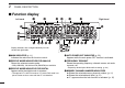
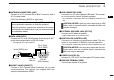
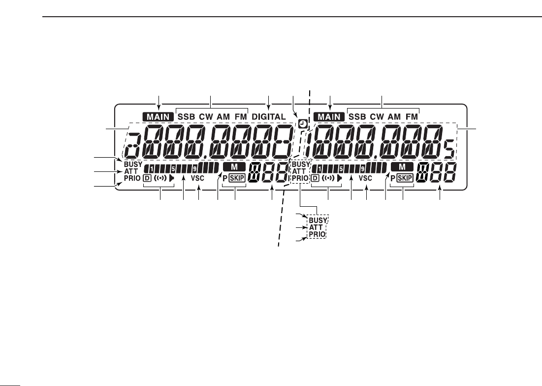
■ Function display
qMAIN INDICATOR (p. 11)
Indicates the main band for function control.
wRECEIVE MODE INDICATORS FOR ANALOG
Shows the selected receive mode.
• SSB (LSB/USB), CW, AM and FM (FM/WFM) are available.
eRECEIVE MODE INDICATOR FOR DIGITAL
Appears while the digital mode is selected.
• The optional UT-118 for DV mode or UT-122 for P25 mode is re-
quired. Some versions come with the UT-122 installed.
rAUTO POWER-OFF INDICATOR (p. 52)
Appears while the auto power OFF function is activated.
tFREQUENCY READOUT
Shows the operating frequency, channel names, set mode
contents, etc.
• Frequency decimal point blinks while scanning. (p. 34)
yMEMORY CHANNEL NUMBER INDICATORS
➥ Shows the selected memory channel number. (p. 11)
➥ Shows the selected bank initial. (p. 31)
➥ “L” appears when the lock function is activated. (p. 15)
Left band Right band
t
t
!3
qewqwr
yyuuoo!0!0
!2
!1!1 ii
!4
!3
!4
!2
*Display indicators are arranged identically for both
the left and right bands.