
Operation Manual

43
DIGITAL MODE OPERATION
9
■ Digital mode operation
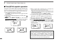
The IC-R2500 can operate in DV*
1
mode or P25*
2
mode
when the optional UT-118 or UT-122 is installed.
*
1
: The optional UT-118 is required.
*
2
: The optional UT-122 is required.
Some versions come with the UT-122 installed.
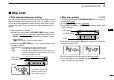
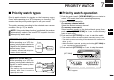
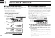
qSelect the left band as the main band.
➥ Push [MAIN•AGC] once to select left band, if necessary.
w Set the operating frequency in digital mode.
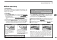
e Push [MODE•SCAN] to enter receive mode select mode
.
rRotate left band’s [DIAL] to select the desired digital mode.
tPush any key to exit receive mode select mode
.
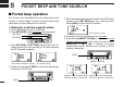
■ Pocket beep operation
This function uses digital code/call sign for calling and can be
used as a “common pager” to inform you that someone has
called while you were away from the receiver. The digital
code or digital call sign squelch does not function during low-
speed data communication in DV mode.
D Waiting for a call from a specific station
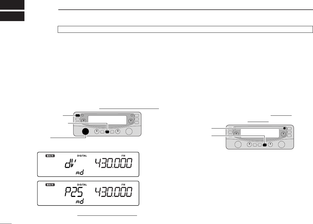
qSelect the left band as the main band.
➥ Push [MAIN•AGC] once to select left band, if necessary.
w Set the operating frequency in DV (P25) mode.
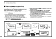
e Program the digital code or call sign in set mode
.
➥ Push
[SET•
SKIP
]
to enter set mode.
➥ Push
[SET•SKIP]
or [ATT•PRIO] several times until
“OPt” appears, then rotate left band’s [DIAL] to select
“On.”
➥ Push
[SET•
SKIP
]
or [ATT•PRIO] several times until de-
sired item appears.
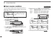
•“CAL” when programming the calls sign for the digital call sign
squelch in DV mode.
•“dCd” when programming the digital code squelch in DV
mode.
•“nA” when programming the NAC code for the digital NAC
squelch in P25 mode.
•“t1” and “U1” when programming the TGID and Unit ID for the
digital selective squelch.
[ATT•PRIO]
[SET•SKIP]
[DIAL]
[MAIN•AGC]
[MODE•SCAN]
UT-118 or UT-122’s installation is described in the IC-PCR2500’s Instruction manual. See the installation details.