INSTRUCTION MANUAL COMMUNICATION RECEIVER iR2500 This device complies with Part 15 of the FCC rules. Operation is subject to the following two conditions: (1) This device may not cause harmful interference, and (2) this device must accept any interference received, including interference that may cause undesired operation.
FOREWORD IMPORTANT Thank you for purchasing this Icom receiver. The IC-R2500 COMMUNICATIONS RECEIVER is designed and built with Icom’s state of the art technology and craftsmanship. With proper care, this receiver should provide you with years of troublefree operation. READ ALL INSTRUCTIONS carefully and completely We want to take a couple of moments of your time to thank you for making the IC-R2500 your radio of choice, and hope you agree with Icom’s philosophy of “technology first.
SUPPLIED ACCESSORIES q OPTIONS UT-106* DSP UNIT Provides AF DSP functions such as noise reduction and auto notch. w UT-108* DTMF DECODER UNIT Provides DTMF decode function for sub band. t e r UT-118* DIGITAL UNIT Provides DV (digital) mode operation. UT-122* DIGITAL UNIT Provides P25 (digital) mode operation. y CP-12L CIGARETTE LIGHTER CABLES For operation and charging via a 12 V cigarette lighter socket. OPC-254L DC POWER CABLES For operation and charging via an external power supply.
PRECAUTIONS RWARNING! NEVER connect the receiver via the NEVER place the receiver where normal operation of the OPC-254L to an AC outlet. This may pose a fire hazard or result in an electric shock. vehicle may be hindered or where it could cause bodily injury. RWARNING! NEVER operate the receiver while driving a vehicle. Safe driving requires your full attention— anything less may result in an accident. NEVER connect the receiver to a power source of more than 14 V DC. This will damage the receiver.
ABOUT APCO PROJECT 25 This device made under license under one or more of the following US patents: #4,590,473, #4,636,791, #5,148,482, #5,185,796, #5,271,017, #5,377,229. The IMBE™ voice coding technology embodied in this product is protected by intellectual property rights including patent rights, copyrights and trade secrets of Digital Voice Systems, Inc. This voice coding Technology is licensed solely for use within this communications equipment.
TABLE OF CONTENTS FOREWORD .............................................................. i IMPORTANT ............................................................... i EXPLICIT DEFINITIONS ............................................ i SUPPLIED ACCESSORIES ...................................... ii SPECIFICATIONS ..................................................... ii OPTIONS ................................................................... ii PRECAUTIONS ..................................................
PRIORITY WATCH ............................................ 38 ■ Priority watch types ........................................ 38 ■ Priority watch operation .................................. 38 8 POCKET BEEP AND TONE SQUELCH ..... 39–42 ■ Pocket beep operation .................................... 39 ■ Tone/DTCS squelch operation ........................ 41 ■ Tone scan ....................................................... 42 9 DIGITAL MODE OPERATION ..................... 43–48 ■ Digital mode operation .
1 CONNECTION ■ Rear panel connection The antenna holder is backed with double-sided tape. Remove the protective paper when the antenna is fixed to any place. The dualwatch operation or diversity operation requires antennas connected to both [ANT1] and [ANT2]. D DC power supply connection Use a 12 V DC power supply with at least 4 A capacity. Make sure the ground terminal of the DC power supply is grounded. • CONNECTING TO A DC POWER SUPPLY Connect to a 12 V DC battery. Pay attention to polarities.
CONNECTION D OPC-1156 connection q Connect the controller plug to the OPC-1156 jack. w Detach the ferrite core from the controller cable, then attach it to the OPC-1156 as shown below. • Make sure to wind the cable on the ferrite core. e Connect the OPC-1156 plug to the [CONTROLLER] connector of the receiver. 1 ■ Antenna installation 1 D Antenna location To obtain maximum performance from the receiver, select a high-quality antenna and mount it in a good location.
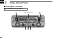
2 PANEL DESCRIPTION ■ Front panel—controller The keys w to t are for the main band only. Function display (pgs. 7, 8) q MAIN AGC w SET PWR SKIP VFO/MR S.MW VFO/MR S.
PANEL DESCRIPTION 2 q POWER KEY [PWR• ] ➥ Push and hold for 1 sec. to turn the controller power ON and OFF. (p. 11) ➥ Continue to hold this key down for 2 sec. after power ON to turn the lock function ON and OFF. (p. 15) t MONITOR•TONE•TONE SCAN KEY [MONI•T/T-SCAN] ➥ Push to turn the monitor function ON and OFF. (p. 14) ➥ Push and hold for 1 sec. to enter the tone function selection mode. (pgs. 34, 41, 44, 46) w SET•SKIP KEY [SET•SKIP] ➥ Push to enter set mode. (p. 49) ➥ Push and hold for 1 sec.
2 PANEL DESCRIPTION The same controls for both the left and right bands are arranged symmetrically. Left band ya u i o MAIN AGC Right band SET PWR SKIP VFO/MR S.MW VFO/MR S.
PANEL DESCRIPTION ya MAIN•AGC KEY [MAIN•AGC] ➥ Push to select the left band as main band. (p. 11) ➥ Push and hold for 1 sec. to turn the AGC (Automatic Gain Control) function ON and OFF. (p. 16) yb MAIN•NB KEY [MAIN•NB] ➥ Push to select the right band as main band. (p. 11) ➥ Push and hold for 1 sec. to turn the NB (Noise Blanker) function ON and OFF. (p. 16) uVFO/MEMORY•MEMORY WRITE KEY [VFO/MR•S.MW] ➥ Push to select from VFO, memory and weather channel* modes. (pgs.
2 PANEL DESCRIPTION ■ Function display Left band q w e r q w Right band t t !4 !3 !2 !1 !0 o i u y *Display indicators are arranged identically for both the left and right bands. !1 !0 o i u y q MAIN INDICATOR (p. 11) Indicates the main band for function control. r AUTO POWER-OFF INDICATOR (p. 52) Appears while the auto power OFF function is activated. w RECEIVE MODE INDICATORS FOR ANALOG Shows the selected receive mode.
PANEL DESCRIPTION u SKIP INDICATORS (p. 36) ➥ “~” appears when the displayed memory channel is specified as a skip channel. ➥ “P~” appears when the displayed frequency is specified as a program skip frequency. i MEMORY INDICATOR (pgs. 11, 23) Appears when memory mode is selected. o VSC INDICATOR (p. 17) Appears when the VSC function is in use. 2 ➥ During P25*2 (Digital) mode operation: ● “ ” appears while the digital NAC squelch function is in use. (p.
2 PANEL DESCRIPTION ■ Rear panel—main unit q Left band w e Rear r q Speaker Right band Power switch Top DC IN ANT 1 GND PACKET 1 PACKET 2 USB EXT SP ANT 2 DATA t i Front u PACKET jack connection AUDIO GND 2-conductor 3.5 (d) mm (1⁄8˝)/100 kΩ 9 y EXT SP jack connection AUDIO GND 2-conductor 3.
PANEL DESCRIPTION q ANTENNA CONNECTORS [ANT] Connect a 50 Ω antenna with a BNC connector and a 50 Ω coaxial cable. [ANT1] for left band, [ANT2] for right band. Two antennas must be connected to [ANT1] and [ANT2] during dualwatch operation or diversity operation. Diversity operation requires two antennas of the same performance in suitable places. Ask your antenna dealer for installation details.
3 SETTING A FREQUENCY ■ Preparation D Turning power ON/OFF [PWR• D VFO and memory modes The receiver has 2 basic operating modes: VFO mode and memory mode. Select VFO mode first to set an operating frequency. ] [VFO/MR•S.MW] ➥ Push [PWR• ] for 1 sec. to turn power ON and OFF. D MAIN band The IC-R2500 can receive signals on both the left and right bands simultaneously. [MAIN•AGC] [MAIN•NB] ➥ Push the desired band’s [MAIN•AGC] or [MAIN•NB] to select the main band. • “Q” indicates the main band.
SETTING A FREQUENCY 3 ■ Tuning step selection When using the tuning dial to change the frequency, or when a scan function is activated, the frequency changes in increments determined by the set tuning step. This can be changed if desired. eRotate the same band’s [DIAL] to select the desired tuning step. 3 The following tuning step are available. • 0.01 kHz (10 Hz) • 0.1 kHz (100 Hz) • 2.5 kHz • 8.33 kHz • 12.5 kHz • 25 kHz • 100 kHz • 200 kHz • 0.02 kHz (20 Hz) • 0.
3 SETTING A FREQUENCY ■ Using the tuning dial ■ Receive mode selection q Rotate the desired band’s [DIAL] to set the frequency. Receive modes are determined by the physical properties of the radio signals. The receiver has 6 receive modes: USB LSB, CW, AM, WFM and FM modes. The mode selection is stored independently in each memory channel. Additionally, IC-R2500 has a DV or P25 mode when the optional UT-118 or UT-122 units are installed, respectively.
BASIC OPERATION 4 ■ Receiving ■ Monitor function q Set the audio level for the main band. ➥ Push the desired band’s [MAIN]. ➥ Push [MONI•T/T-SCAN] to open the squelch. ➥ Rotate the main band’s [VOL] to adjust the audio level. ➥ Push [MONI•T/T-SCAN] to close the squelch. w Set the squelch level. ➥ Rotate the main band’s [SQL] fully counterclockwise in advance, then rotate [SQL] clockwise until the noise just disappears. eSet the operating frequency in the main band. (pgs.
4 BASIC OPERATION ■ Lock function ■ Attenuator function To prevent accidental frequency changes and unintentional function access, use the lock function. The attenuator prevents a desired signal from being distorted when very strong signals are near the desired frequency or when very strong RF fields, such as from a broadcasting station, are near your location. The attenuator reduces signal strength by about 20 dB and this function can be activated on 1300 MHz or below.
BASIC OPERATION 4 ■ NB function ■ AGC function The NB (noise blanker) function removes pulse-type noise when SSB, CW or AM mode is selected. The AGC (Automatic Gain Control) function controls receiver gain to produce a constant audio output level even when the received signal strength varies from fading, etc. A slow-response AGC function is selectable for SSB, CW or AM mode. ➥ After pushing [MAIN] to select the desired band (left or right) as the main band, push and hold [MAIN•NB] for 1 sec.
4 BASIC OPERATION ■ AFC function [ The AFC (Automatic Frequency Control) function tunes the displayed frequency automatically when an off-center frequency is received. It activates in FM mode and only when the selected IF filter is 6 kHz or 15 kHz. q Push the desired band’s [MAIN] to select the main band. w Select FM mode. e Push [SET•SKIP] to enter set mode. r Push [SET•SKIP] or [ATT•PRIO] several times until “AFC” appears.
BASIC OPERATION ■ IF filter selection [ The receiver has 2 to 4 IF passband filter widths for each mode. Selectable passband widths are 3, 6, 15, 50 and 230 (depending on the selected mode). • Selectable passband width for each mode. SSB mode : 3 (2.8 kHz) or 6 kHz CW mode : 3 (2.8 kHz) or 6 kHz AM mode : 3 (2.8 kHz), 6 kHz, 15 kHz or 50 kHz WFM mode: 50 kHz or 230 kHz FM mode : 6 kHz, 15 kHz or 50 kHz q Push the desired band’s [MAIN] to select the main band. w Push [SET•SKIP] to enter set mode.
4 BASIC OPERATION ■ Duplex operation Duplex communication uses two different frequencies for transmitting and receiving. Generally, duplex is used in communication through a repeater, some utility communications, etc. tPush [SET•SKIP] once to advance to the offset frequency setting item. yRotate the main band’s [DIAL] to set the desired offset frequency within 0.000–1000.000 MHz range.
BASIC OPERATION 4 ■ Weather channel operation (USA/CANADA versions only) D Operation q Set the receive station frequency (repeater output frequency). wPush [MONI•T/T-SCAN] to monitor the transmit station frequency (repeater input frequency) directly. [MONI•T/T-SCAN] D Weather channel selection q Push [VFO/MR•S.MW] to select memory mode in the desired band (left or right). w Push [MHz•TS] to enter memory type selection mode. [VFO/MR•S.
4 BASIC OPERATION D Weather alert function NOAA broadcast stations transmit weather alert tones before important weather announcements. When the weather alert function is turned ON, the selected weather channel is monitored each 5 sec. for the announcement. When the alert signal is detected, the “ALt” and the WX channel are displayed alternately and sounds a beep tone until the receiver controls are manipulated.
BASIC OPERATION 4 ■ Single band operation D Single band/Dualwatch operation D Diversity operation Dualwatch operation monitors two frequencies simultaneously. The IC-R2500 has two independent receiver circuits: left band, and right band (available frequencies, operating mode and functions are different depending on bands). Single band operation is useful when only one frequency is being watched. The right band can be inhibited.
5 MEMORY OPERATION ■ General description ■ Memory channel selection The receiver has 1100 memory channels including 100 scan edge memory channels (50 pairs) for storage of often-used frequencies. And a total of 21 memory banks, A to H, J to R, T, U, W and Y are available for storing groups of frequencies, etc. Up to 100 channels can be assigned to a bank. q Push the desired band’s [VFO/MR•S.MW] once or twice to select memory mode. • “M” indicator appears. [VFO/MR•S.
MEMORY OPERATION 5 ■ Programming a memory channel VFO settings, including the set mode contents such as subaudible tone frequency, offset and scan skip information can be programmed into a memory channel. qSet the desired frequency in the desired band (left or right). ➥ Push the desired band’s [VFO/MR•S.MW] once or twice to select VFO mode. ➥ Set the frequency using the same band’s [DIAL]. ➥ Set other data (e.g. tone frequency, duplex information, etc.) if required.
5 MEMORY OPERATION ■ Programming channel names Each memory channel can be programmed with an alphanumeric channel name for easy recognition and can be indicated independently by channel. Names can be a maximum of 6 characters— see the table on next page for available characters. e Push [SET•SKIP] several times to select the memory name programming condition, “m nAmE.” q Select the desired memory channel to be programmed. ➥ Push [VFO/MR•S.
MEMORY OPERATION D To indicate the channel name • Available characters (space) (A) (B) (C) (D) (E) (F) (G) (H) (I) (J) (K) (L) (M) (N) (O) (P) (Q) (R) (S) (T) (U) (V) (W) (X) (Y) (Z) (0) (1) (2) (3) (4) (5) (6) (7) (8) (9) (+) (–) (/) (=) 5 [ The channel name indication can be set independently for each memory channel. q Select the desired memory channel in the main band. ➥ Push [VFO/MR•S.
5 MEMORY OPERATION ■ Copying memory contents This function transfers a memory channel’s contents to VFO (or another memory channel). This is useful when searching for signals near a memory channel frequency and for recalling the subaudible tone frequency, etc. D Memory➪VFO qSelect the desired band’s (left or right) memory channel to be transferred. ➥ Push the desired band’s [VFO/MR•S.MW] several times to select memory mode, then rotate the same band’s [DIAL] to select the desired memory channel.
MEMORY OPERATION 5 D Memory➪memory qSelect the desired band’s (left or right) memory channel to be transferred. ➥ Push the desired band’s [VFO/MR•S.MW] several times to select memory mode, then rotate the same band’s [DIAL] to select the desired memory channel. • “!” and memory channel number appear. w Push and hold the same band’s [VFO/MR•S.MW] for 1 sec. to enter select memory write mode. e Rotate the same band’s [DIAL] to select the target memory channel.
5 MEMORY OPERATION ■ Memory clearing Contents of programmed memories can be cleared (erased), if desired. q Push [VFO/MR•S.MW] to select VFO mode in the main band. w Push the same band’s [VFO/MR•S.MW] for 1 sec. to enter select memory write mode. • “!” indicator and the memory channel number blink. e Rotate the same band’s [DIAL] to select the memory channel to be cleared. r Push [SET•SKIP] three times to select “CLEAR,” then push and hold [VFO/MR•S.MW] for 1 sec. • 3 beeps sound.
MEMORY OPERATION ■ Memory bank setting The IC-R2500 has a total of 21 banks (A to H, J to R, T, U, W, Y). Regular memory channels, 0 to 999, may assigned into the desired bank for easy memory management. q Select the desired memory channel. ➥ Push [VFO/MR•S.MW] to select memory mode in the main band, then rotate the same band’s [DIAL] to select the desired memory channel. • “!” and memory channel number appear. w Push and hold the same band’s [VFO/MR•S.MW] for 1 sec. to enter select memory write mode.
5 MEMORY OPERATION ■ Memory bank selection ■ Transferring bank contents q Push [VFO/MR•S.MW] to select memory mode in the desired band (left or right). w Push [MHz•TS] to enter memory type selection mode. The bank contents of programmed memory channels can be cleared or transferred to another bank. INFORMATION: Even if the bank is cleared of memory channels, the memory channel contents still remain programmed. [VFO/MR•S.
MEMORY OPERATION w Push [VFO/MR•S.MW] for 1 sec. to enter select memory write mode. • “!” indicator and the memory channel number blink. 5 r Rotate the same band’s [DIAL] to select the desired bank indicator to transfer or erase. • Push [ATT•PRIO] to toggle the bank or bank channel selection. • Select “– –” indication when erasing the contents from the bank. • Vacant bank channel numbers are only be displayed. 5 Memory channel blinks e Push [SET•SKIP] once to select “bAnk.
6 SCAN OPERATION ■ Scan types Scanning searches for signals automatically and makes it easier to locate new stations. FULL SCAN (p. 34) 10 kHz 3299.9999 MHz Some frequency ranges are not scanned according to the frequency coverage of the receiver’s version. Scan Jump MEMORY (SKIP) SCAN (p. 34) SKIP M1 M2 M3 M 199 M6 M5 M0 M4 SKIP FREQUENCY/MEMORY SKIP FUNCTION (p. 36) Band edge Band edge Scan SKIP 33 Jump Repeatedly scans all frequencies over the entire band.
SCAN OPERATION 6 ■ Scan start/stop D Preparation Scan resume condition (p. 37); program scan edges (p. 35); program two or more memory channels (p. 24); set skip settings (p. 36), if desired. IMPORTANT!: To perform memory or bank scan, two or more memory/bank channels MUST be programmed, otherwise the scan will not start. D Operation qPush [VFO/MR•S.MW] once or twice to select VFO mode for full/programmed scan; or to select memory mode for memory/bank scan.
6 SCAN OPERATION ■ Scan edges programming Scan edges can be programmed in the same manner as memory channels. Scan edges are programmed into scan edges, 0A/0B to 49A/49B, in memory channels. q Push the desired band’s [VFO/MR•S.MW] once or twice to select VFO mode. w Set the edge frequency of the desired frequency range: ➥ Set the frequency using the same band’s [DIAL]. ➥ Set other data (e.g. tone squelch, etc.), if desired. e Push and hold the same band’s [VFO/MR•S.MW] for 1 sec.
SCAN OPERATION 6 ■ Skip scan D Skip channel/frequency setting D Skip scan setting You can set the selected memory channel as a skip channel which is skipped during memory skip scan. In addition, it can be set as a skip channel for both memory skip scan and frequency skip scan. These are useful to speed up the scan interval. q Push the main band’s [VFO/MR•S.MW] once or twice to select VFO mode. w Push [SET•SKIP] to enter set mode. e Push [SET•LOCK] or [ATT•PRIO] several times until “PSC” appears.
6 SCAN OPERATION ■ Scan resume condition The scan resume condition can be selected a timed timer or pause scan. The selected resume condition is also used for priority watch. (p. 38) The display shows that the scan will resume 15 sec. after it stops. q Push [MAIN•AGC] (or [MAIN•NB]) to select the desired band (left or right) as the main band. w Push [SET•SKIP] to enter set mode.
PRIORITY WATCH 7 ■ Priority watch types ■ Priority watch operation Priority watch checks for signals on the frequency every 5 sec. while operating on a VFO frequency or scanning. The receiver has two priority watch types to suit your needs. q Push the main band’s [VFO/MR•S.MW] once or twice to select VFO mode; then set an operating frequency. w Set the watched channel(s). For memory channel watch: Select the desired memory channel.
8 POCKET BEEP AND TONE SQUELCH ■ Pocket beep operation This function uses subaudible tones for calling and can be used as a “common pager” to inform you that someone has called while you were away from the receiver. t When operating the pocket beep function with DTCS code squelch, push [SET•SKIP] once then rotate the main band’s [DIAL] to select the DTCS polarity. D Waiting for a call from a specific station q Set the operating frequency in FM mode. w Push [SET•SKIP] to enter set mode in the main band.
POCKET BEEP AND TONE SQUELCH i Push any key for the main band or any of the shared keys below the display to exit tone squelch selection mode. Appears when the pocket beep with tone squelch is activated. Appears when the pocket beep with DTCS squelch is activated. o When a signal with a matching tone is received, the receiver emits beep tones and blinks “S.” • Beep tones sound for 30 sec. and “S” blinks. To stop the beeps and blinking manually, push any key. 8 D Available tone frequency list 67.0 69.
8 POCKET BEEP AND TONE SQUELCH ■ Tone/DTCS squelch operation The tone or DTCS squelch opens only when receiving a signal with the same pre-programmed subaudible tone or DTCS code. You can silently wait for a signal using the same tone. q Set the operating frequency in FM mode. • Push [MAIN] to select the desired band (left or right) as the main band in advance. w Program the CTCSS tone frequency or DTCS code in set mode. (p. 39) e Push and hold [MONI•T/T-SCAN] for 1 sec.
POCKET BEEP AND TONE SQUELCH 8 ■ Tone scan By monitoring a signal using with pocket beep, tone or DTCS squelch, you can determine the tone frequency or DTCS code necessary to open the squelch. q Set the desired operating frequency or memory channel to be checked for a tone frequency or code. • Push [MAIN] to select the desired band (left or right) as the main band in advance.
9 DIGITAL MODE OPERATION UT-118 or UT-122’s installation is described in the IC-PCR2500’s Instruction manual. See the installation details. ■ Digital mode operation DV*1 ■ Pocket beep operation P25*2 The IC-R2500 can operate in mode or when the optional UT-118 or UT-122 is installed. mode *1: The optional UT-118 is required. *2: The optional UT-122 is required. Some versions come with the UT-122 installed. q Select the left band as the main band.
DIGITAL MODE OPERATION r Rotate the left band’s [DIAL] to select the desired call sign or code. • DV mode operation • Push [MODE•SCAN] (or [MONI•T/T-SCAN]) to move the cursor. [MONI•T/T-SCAN] [DIAL] [MODE•SCAN] t Push any key for the main band to exit set mode. y Push and hold [MONI•T/T-SCAN] for 1 sec.
9 DIGITAL MODE OPERATION ■ Digital squelch operation u Push any key for the main band or any of the shared keys below the display to exit tone squelch selection mode. While in DV mode operation, the digital call sign (DSQL) or digital code squelch opens only when receiving a voice signal with the same pre-programmed digital call sign or code, respectively. While in P25 mode operation, 2 types of digital squelch, NAC or Selective, are available.
DIGITAL MODE OPERATION 9 r Rotate the left band’s [DIAL] to select the desired call sign or code. • Push [MODE•SCAN] (or [MONI•T/T-SCAN]) to move the cursor. [MONI•T/T-SCAN] Digital squelch OFF • DV mode operation [DIAL] [MODE•SCAN] t Push any key for the main band to exit set mode. y Push and hold [MONI•T/T-SCAN] for 1 sec. to enter tone squelch selection mode, then rotate left band’s [DIAL] until “ ” or “ ” appears in the function display.
9 DIGITAL MODE OPERATION ■ Call sign programming (for DV mode) Sets your own call sign for digital call sign squelch operation. Up to 8 characters are programmable. q Push [SET•SKIP] to enter set mode. w Push [SET•SKIP] or [ATT•PRIO] several times until “OPt” appears, then rotate main band’s [DIAL] to select “On.” [SET•SKIP] [VFO/MR•S.MW] [ r Rotate main band’s [DIAL] to select the desired character or code. • Push [MODE•SCAN] or [MONI•T/T-SCAN] to move the cursor to right or left, respectively.
DIGITAL MODE OPERATION ■ ID code programming (for P25 mode) Sets the desired NAC code for P25 digital (NAC) squelch or TGID/Unit ID for P25 digital (Selective) squelch operation. q Push [SET•SKIP] to enter set mode. w Push [SET•SKIP] or [ATT•PRIO] several times until “OPt” appears, then rotate main band’s [DIAL] to select “On.” [SET•SKIP] [VFO/MR•S.MW] 9 [ t Push [MODE•SCAN] to select 2nd digit, then rotate main band’s [DIAL] to select the desired code. • 2nd digit blinks (1st digit stop blinking).
10 SET MODE ■ General • Set mode operation q Push the desired band’s [MAIN] to select the main band. w Push [SET•SKIP] to enter set mode. e Push [SET•SKIP] or [ATT•PRIO] to select the desired item. r Rotate the main band’s [DIAL] to select the condition or value. t Push any key for main band or or any of the shared keys below the display to exit set mode.
SET MODE • TSQL frequency • DTCS code • DTCS polarity • VSC function • Scan resume timer FM/AM/SSB/CW mode only Memory mode only • Offset frequency Bank link-On • Bank link function‡ • Memory name‡ • Scan skip area† • Program skip† VFO mode only FM mode only • Duplex direction • AFC function*2 USA/CANADA versions only • IF filter SSB/CW mode only • Weather alert*1 • IF shift*3 • Squelch delay • Sub band setting When the UT-106 is installed • Optional items setting*5 • NR function*4
10 SET MODE D Set mode items for DV mode • DV unit power setting • Call sign setting • Digital code • Data speed • Standby beep These items appear when the UT-118 is installed, and Optional items setting is ON. : Push : Push SET SKIP ATT PRIO • Rx Call sign display • Digital monitor • Rx message display • Rx Call sign Return to set mode ((p.
SET MODE 10 D Key-touch beep D Auto power OFF The key-touch beep can be turned OFF for silent operation. (default: ON) The receiver can be set to automatically turn OFF with a beep after a specified period during which no key operations are performed. 30 min., 1 hour, 2 hours and OFF can be specified. The specified period is retained even when the receiver is turned OFF by the auto power OFF function. To cancel the function, select “OF” for this item in set mode.
10 SET MODE D Display color D Duplex direction The display color can be set to amber (default) or green. Sets the duplex direction. The displayed frequency shifts by the programmed offset frequency (see next item) when monitor function is in use (pushing [MONI•T/T-SCAN]). • OFF : Simplex operation. (default) • DUP– : The displayed frequency shifts down during monitor. • DUP+ : The displayed frequency shifts up during monitor.
SET MODE 10 D Tone frequency D DTCS code Sets subaudible tone frequency for tone squelch operation. Total of 51 tone frequencies (67.0–254.1 Hz) are available. (default: 88.5 Hz) Sets DTCS code for DTCS squelch operation. Total of 104 codes (023–754) are available. (default: 023) • Available DTCS code list • Available tone frequency list 67.0 69.3 71.0 71.9 74.4 77.0 79.7 82.5 85.4 88.5 91.5 94.8 097.4 100.0 103.5 107.2 110.9 114.8 118.8 123.0 127.3 131.8 136.5 141.3 146.2 151.4 156.7 159.8 162.
10 SET MODE D VSC setting D Program scan skip setting Turns VSC (Voice Squelch Control) ON and OFF. (default: OFF) Sets the program scan skip setting ON and OFF for VFO scan operation, such as programmed scan. (default: ON) This item appears when set mode is accessed from VFO mode only. D Scan resume timer Selects scan resume timer from SCT-15 (default), SCT-10, SCT-5 and SCP-2. Scan resumes after the specified period when the received signal disappears. • SCT-15/10/5 : Scan pauses for 15/10/5 sec.
SET MODE 10 D Memory name setting Sets memory name appearance ON (appear) and OFF (does not appear; default). This item appears when set mode is accessed from memory mode only. D Memory bank link function Sets the memory bank link function ON and OFF (default). The link function provides continuous banks scan, that scans all contents in the selected banks during bank scan. This item appears when set mode is accessed from memory mode only.
10 SET MODE D AFC setting D IF shift frequency setting Turns AFC (Automatic Frequency Control) function ON and OFF. (default: OFF) Select the IF shift frequency up to ±25 steps (in 1 step: 50 Hz). This item appears when the receive mode is selected SSB or CW mode only. D Filter setting Center position (default) Select the IF filter passband width from 3, 6, 15, 50 and 230 kHz (depending on the selected mode.) Highest D Sub band setting Turns the sub band setting ON and OFF.
SET MODE 10 D Squelch delay D NR setting Selects squelch delay to short or long to prevent repeated opening and closing of the squelch during reception of the same signal. •S : Short squelch delay. •L : Long squelch delay. Selects NR (Noise Reduction) level from 1 to 15 and OFF (default). The NR function enhances desired signals in the presence of noise by using the DSP circuit. The amount of enhancement is adjustable. The NR level can result in audio signal masking.
10 SET MODE D DV unit power setting D Digital code setting Selects the DV unit (UT-118) power setting from Auto and ON. ☞This item appears when optional UT-118 is installed and Optional items setting (p. 58) is ON. • At : DV unit is turned ON automatically when digital mode is selected. (default) • On : DV unit is turned ON when the receiver is powered ON. Sets the desired digital code for digital code squelch operation. Total of 100 codes (00–99) are available.
SET MODE 10 D Standby beep setting D Auto RX call sign display Sets beep emission to ON or OFF when the receiving station finishes transmission or the receiving signal disappears. (default: ON) ☞This item appears when optional UT-118 is installed and Optional items setting (p. 58) is ON. When this setting is ON, transmitter’s call sign is displayed automatically. (default: ON) ☞This item appears when optional UT-118 is installed and Optional items setting (p. 58) is ON.
10 SET MODE D RX call sign indication D RX RPT2 call sign indication This item stores and indicates the newest received call sign. The received call sign is cleared once the receiver is turned OFF. ☞This item appears when optional UT-118 is installed and Optional items setting (p. 58) is ON. This item stores and indicates the newest received RPT2 call sign. The received call sign is cleared once the receiver is turned OFF.
SET MODE 10 D RX call sign with message indication This item stores and indicates the newest received call sign with message. The received call sign is cleared once the receiver is turned OFF. ☞This item appears when optional UT-118 is installed and Optional items setting (p. 58) is ON. North or South Degrees MONI Push T/T-SCAN Push MODE SCAN Minutes Seconds Appears (DDDDDD: Call sign example) • Push [MODE•SCAN] (or [MONI•T/T-SCAN]) to move the cursor.
10 SET MODE D P25 unit power setting D TGID code setting Selects the P25 unit (UT-122) power setting from Auto and ON. ☞This item appears when optional UT-122 is installed and Optional items setting (p. 58) is ON. • At : P25 unit is turned ON automatically when digital mode is selected. (default) • On : P25 unit is turned ON when the receiver is powered ON. Sets the desired TGID code for P25 digital (Selective) squelch operation. TGID code is selectable from 0–65535.
SET MODE 10 D Auto RX ID display D RX TGID indication When this setting is ON, transmitter’s ID is displayed automatically. (default: ON) ☞This item appears when optional UT-122 is installed and Optional items setting (p. 58) is ON. This item stores and indicates the newest received TGID. The received ID is cleared once the receiver is turned OFF. ☞This item appears when optional UT-122 is installed and Optional items setting (p. 58) is ON.
11 OTHER FUNCTIONS UT-106 installation is described in the IC-PCR2500’s Instruction manual. See the installation details. ■ DSP operation (Optional UT-106 is required) D ANF function [ The ANF (Automatic Notch Filter) function automatically attenuates beat tones, tuning signals, etc., even if they’re frequency changes. This function can be activated in SSB, AM, FM modes. q Select any of SSB, AM or FM mode in the desired band (left or right). w Push [SET•SKIP] to enter set mode.
OTHER FUNCTIONS 11 ■ DATA cloning (IC-PCR2500 control software must be installed) Cloning allows you to quickly and easily transfer the programmed contents from a personal computer to a receiver using the IC-PCR2500 control software. D Cloning using a personal computer Data can be cloned to and from a personal computer (Microsoft® Windows® XP/2000/Me/98SE) and other settings can also be programmed from a PC. Consult the IC-PCR1500/ICPCR2500’s Instruction manual for cloning details.
11 OTHER FUNCTIONS ■ Partial reset AT POWER ON ■ All reset AT POWER ON If you want to initialize the operating conditions (VFO frequency, VFO settings, set mode contents) without clearing the memory contents, a partial reset function is available. The function display may occasionally display erroneous information (e.g. when first applying power). This may be caused externally by static electricity or by other factors. ➥ While pushing either band’s [VFO/MR•S.
OTHER FUNCTIONS ■ Internal audio switch The internal switch must be set properly to use an external speaker, headphones or earphone. CAUTION: DISCONNECT the AC adaptor or DC power cable from the receiver Main unit before performing any work on the receiver. qTurn the receiver Main unit power OFF, then disconnect the AC adaptor or DC power cable. wUnscrew the 8 screws and disconnect the connected cables, then remove the top cover. • Be careful not to lose the screws.
12 TROUBLESHOOTING If your receiver seems to be malfunctioning, please check the following points before sending it to a service center. PROBLEM Does not turn on. POSSIBLE CAUSE SOLUTION • The AC adapter is not fully seated in the power • Check the connection. jack on the rear panel. • Rotate [VOL] to obtain a suitable level. No sound comes from the • Volume level is too low. • Rotate [SQL] to set the squelch level. • Squelch level is set too high. speaker.
DOC DECLARATION OF CONFORMITY We Icom Inc. Japan 1-1-32, Kamiminami, Hirano-ku Osaka 547-0003, Japan Declare on our sole responsibility that this equipment complies with the essential requirements of the Radio and Telecommunications Terminal Equipment Directive, 1999/5/EC, and that any applicable Essential Test Suite measurements have been performed. Kind of equipment: Type-designation: COMMUNICATIONS RECEIVER iPCR2500/R2500 Düsseldorf 24th Mar.
MEMO 71
MEMO 1 2 3 4 5 6 7 8 9 10 11 12 13 14 15 16 72
#02 Europe ■ GER ■ FRA ■ ESP ■ SWE ■ AUT ■ NED ■ POR ■ DEN ■ GBR ■ BEL ■ ITA ■ FIN ■ IRL ■ LUX ■ GRE ■ SUI ■ NOR #03 U.K. ■ GER ■ FRA ■ ESP ■ SWE ■ AUT ■ NED ■ POR ■ DEN ■ GBR ■ BEL ■ ITA ■ FIN ■ IRL ■ LUX ■ GRE ■ SUI ■ NOR #06 France ■ GER ■ FRA ■ ESP ■ SWE ■ AUT ■ NED ■ POR ■ DEN ■ GBR ■ BEL ■ ITA ■ FIN ■ IRL ■ LUX ■ GRE ■ SUI ■ NOR A-6510H-1EX-q Printed in Japan © 2006 Icom Inc.