FOREWORD ICON announces the debut of the first 1.2GHz handheld transceiver to enter the Amateur radio field, the Exceptionable versatile yet surprisingly compact and easy to handle, the is a complete, high performance UHF handheld the beneficiary of the very latest in ICON technical know-how and state-of-the-art UHF engineering. To fully enjoy the many features of your new handheld, please study the instruction manual thoroughly prior to operation.
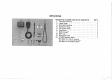
UNPACKING Accessories included with the aTy. 1. Flexible antenna 1 2. Hand strap. . 1 3. Microphone plug o1 4. Earphone plug. , .. 1 5. DC power plug 1 6. Earphone. . 1 7. Wall charger® Belittle .. 1 9. Rainproof cap 1 10. IC-BP3 battery pack *BC-25U for U.S.A.
BRI ®MOISTURE PROOF ®SLIDE-ON BATTERY PACK ®POWER MODULE OPERATION ¢10 MEMORY CHANNELS The is ruggedly constructed with rubber gaskets between the transceiver covers and chassis, ensuring that moisture will never be a problem when operating in practically any environment. _The supplied IC-BP3 BATTERY PACK easily slides off and on the transceiver body for quick removal or attachment. Once attached it will stay in place due to a quick-release lock button designed to prevent accidental removal.
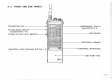
2-1 TOP PANEL @ RF POWER OUTPUT SELECTOR SWITCH @EXTERNAL DC POWER JACK @ANTENNA CONNECTOR (EXTERNAL SPEAKER JACK ] @TRANSMIT/RECEIVE INDICATOR ] @EXTERNAL MICROPHONE JACK ® VXO/RIT SELECTOR SWITCH @®LIGHT SWITCH @POWER/VOLUME CONTROL @®SQUELCH CONTROL ®VXO/RIT CONTROL
2-2 FRONT AND SIDE PANELS E @FUNCTION ] @ TONE-BURST {See SECTION @PUSH-TO-TALK (PTT) BATTERY PACK RELEASE BUTTON—> 40 FREQUENCY DISPLAY (See SECTION 2 5) @KEYBOARD INTERNAL SPEAKER @INTERNAL MICROPHONE ®BATTERY PACK
2-3 REAR PANEL (BATTERY PACK) @CHARGER JACK @BATTERY CHARGE INDICATOR IC-BP3 BATTERY PACK 2-4 BOTTOM VIEW @POSITIVE TERMINAL @NEGATIVE TERMINAL: B CHARGE TERMINAL
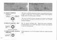
W TOP PANEL (1) ANTENNA CONNECTOR @ EXTERNAL SPEAKER JACK [EXT. sP] (& TRANSMIT/RECEIVE INDICATOR [MARXIST] (4) EXTERNAL MICROPHONE JACK [Mic] Connect the supplied flexible antenna. All antennas connected to the transceiver must be 50 ohms and have a TNC connector. Connect either an 8 ohm external speaker or the supplied earphone for private listening. The INTERNAL SPEAKER will not operate if an external speaker is connected to the EXTERNAL SPEAKER JACK.
(5) VXO/RIT CONTROL [VXO/RIT] Lowers the '/4\ Raises the frequency. [ frequency. VX0 (6)SQUELCH CONTROL [sail} Raises the threshold level. i SQUELCH CONTROL (D) POWER/VOLUME CONTROL [FRIVOLITY Increases the audio level. N~ or rd » This control shifts the receive and transmit frequencies up and down to KHz on either side of the frequency indicated on the frequency display when the VXO function is selected.
(® LIGHT SWITCH [LIGHT] (@ VXO/RIT SELECTOR SWITCH {vol [RIT] ) RF POWER OUTPUT SELECTOR SWITCH [HIGH] [Low] (EXTERNAL DC POWER JACK [DC IN] [13.8V] The [DC IN]. [13.8V] jack accepts voltages between 12V and 15V. However, the transceiver does not work when supplying more than 16V. Press this switch down to turn on the back light for the FREQUENCY DISPLAY. This switch selects either the VXO or RIT function for fine tuning. When this switch is set in the LOW position (IN), the output power is reduced to 0.
W FRONT AND SIDE PANELS 12 KEYBOARD () INTERNAL SPEAKER {INTERNAL MICROPHONE (BATTERY PACK (BATTERY PACK RELEASE BUTTON [RELEASE] @PUSH-TO-TALK (PTT) SWITCH A® TONE-BURST SWITCH {1C-12E version only) This keyboard has 16 keys consisting of ten numerical keys and six code keys. Some keys have dual functions. See SECTION 4 3 KEY FUNCTIONS. The internal speaker operates when the transceiver is receiving. However, it will not operate if an external speaker is connected to the EXTERNAL SPEAKER JACK.
(FUNCTION KEY [FUN] @FREQUENCY DISPLAY B REAR PANEL @CHARGER JACK @)BATTERY CHARGE INDICATOR W BOTTOM VIEW @POSITIVE TERMINAL @) NEGATIVE TERMINAL @) CHARGE TERMINAL Push this key to select the secondary function of each key. See SECTION-4-3 KEY FUNCTIONS. Indicates not only the operating frequency but also several other functions. See SECTION 2 -5 FREQUENCY DISPLAY. This jack accepts the output plug of the supplied BC-25U, BC-26E and BC-27 WALL CHARGERS or suitable power sources.
-10 — 2-5 FREQUENCY DISPLAY ® ® TRANSMIT INDICATOR “T" @® SCAN INDICATOR “8” © LOCK INDICATOR “L” © BATTERY CONDITION INDICATOR “v " “T* appears when the transceiver is in the transmit mode. 8 appears when the transceiver is in a scan mode. Refer to SECTION 5-9 SCANNING OPERATION. “L"” appears when the operating frequency is locked. At this time, any key entries will be canceled, except the [FUN] and keys when they are used to clear the lock function. Refer to SECTION 510 LOCK FUNCTION.
€ TONE ENCODER INDICATOR "y @®PRIORITY FUNCTION INDICATOR ©FREQUENCY DISPLAY © S/RF INDICATOR “ppuEpnRnay’’ () MEMORY CHANNEL INDICATOR * See SECTION 5-1 for DIAL MODE. ** See SECTION 5-1 for MEMORY MODE. ***gee SECTION 6 -7 for CALL CHANNEL OPERATION. 4} appears when the sub audible tone encoder {IC-12AT only} is actuated. Refer to SECTION 5-13 SETTING SUB AUDIBLE TONE ENCODER FREQUENCY. “. 1 appears when the transceiver is in the PRIORITY FUNCTION. Refer to SECTION 5 8 PRIORITY FUNCTION.
12 — & MEMORY MODE INDICATOR g (® DUPLEX MODE INDICATORS raper ow__ie “M" appears when the transceiver is in the MEMORY MODE. Refer to SECTION 56 MEMORY READING. Appear while the is being operated in DUPLEX MODE (transmit frequency differs from receive frequency). Both indicators disappear while operating in SIMPLEX MODE. Refer to SECTION 5-4 DUPLEX OPERATION.
e S 3-1 BATTERY INSTALLATION (1) Using the IC-BP3 BATTERY PACK See (2) below for further information regarding battery charging. (2) BATTERY CHARGING The supplied IC-BP3 BATTERY PACK is rechargeable and can be slipped ON or OFF the transceiver very easily. To recharge the battery pack use the supplied wall charger or the optional desk charger, or a Teletype cigarette lighter socket with the IC-CP1 CIGARETTE LIGHTER CABLE.
214 — ®BATTERY PACK NOTE (3) EXTERNAL POWER SOURCE 2) It is not necessary for the IC-BP3 BATTERY PACK to be attached to the transceiver for recharging, but sure that the POWER SWITCH on the transceiver is turned completely OFF before starting the charge. 3) It takes about 15 hours to charge the battery pack completely. For use at home or in a car, use an external power source which assures you of stable communication without concern for battery consumption, .
3-2 ANTENNA CONNECTION 3-3 FOR OUTDOOR USE Insert the connector on the flexible rubber antenna into the ANTENNA CONNECTOR on the top panel. Screw down securely. FOR EXTERNAL ANTENNA CONNECTION: s Select a high performance antenna and set it up in the highest position, « Use a 50 ohm antenna and coaxial cable with TNC plug. 1) Attach the belt clip to the rear panel using the two supplied screws and plastic washers.
RN 4-1 RECEIVING Verify that the [PROVOLONE] CONTROL is in the OFF position before connecting power to the transceiver. Refer to SECTION 5 for further information. 1) Rotate the POWER/VOLUME CONTROL clockwise beyond the “click’” to turn power ON. 2) Rotate the SQUELCH CONTROL fully counterclockwise. Rotate the POWER/VOLUME CONTROL clockwise to a comfortable listening level. 3} If only noise with no signal is heard from the speaker, rotate the SQUELCH CONTROL clockwise until the noise is quieted.
-18 — 4-2 TRANSMITTING 4.3 “KEY FUNCTIONS Following are procedures for general transmitting. Refer to0 SECTION 5 FUNCTIONS OPERATION for further information. 1) Press the PTT SWITCH to begin transmitting. The letter “T appears on the display to indicate a signal is being transmitted. 2) Speak into the microphone using your normal voice level. 3) Release the PTT SWITCH to return to the receive mode. Some keys have dual functions.
5-1 DIAL MODE AND MEMORY MODE (1) FUNCTIONS [N DIAL MODE (2) FUNCTIONS IN MEMORY MODE SECTION 5 FUNCTIONS OPERATION. The has two different operating modes, DIAL MODE and MEMORY M}ODE.
(3) FUNCTIONS IN BOTH DIAL AND MEMORY MODES 5-2 SETTING FREQUENCY (1) USING DIGIT KEYS 1) To set an operating frequency, push the appropriate digit keys for the desired frequency, following the pattern below. Press four digit keys beginning with the MHz" digit and ending with the “*10kHz"’ digit. 1C-12E: Press four digit keys beginning with the “10MHz"" digit and ending with the kHz digit. The last digit key pushed enters the frequency as shown in the table below.
2) If illegal ‘digits or an out-of-band frequency have been entered, the digits are canceled and the previous operating frequency will be recalled. 3) When a wrong key has been pushed, press the key. The entered digits are canceled and the previous operating frequency will be recalled.
USING [A] or KEY 1) With each push of the or key, the operating frequency will be changed one increment up or down with the specified frequency step rate respectively. See SECTION 5-3 SETTING FREQUENCY STEP RATE. 2) In the same way, key down, shift the operating frequency up or down continuously.
5-3 SETTING FREQUENCY 1) Push and hold the [FUN] key, push the key and STEP RATE . then push a key to determine the step rate for setting the fre* quench step rate and release the [FUN] key. 2) The frequency step rate allocated to each key is showdown in the following table. I an illegal number has been’entered, the number is canceled and the previous rate number will be recalled.
5-4 DUPLEX OPERATION (1) SETTING THE OFFSET FREQUENCY -26 — . Transmit offset refers to the frequency difference between the receive and transmit frequencies when using DUPLEX MODE. 1) While pushing the [FUN] key, push the key, then the four digit keys of the desired offset frequency. Offset frequency settings can be made in kHz steps. IC-12E: Offset frequency settings can be made in 12.5kHz steps. The last digit key pushed enters the frequencies shown in the table below.
(2) SETTING DUPLEX MODE 1) While pushing the [FUN] key, push either for —duplex or for +duplex to make a setting in DUPLEX MODE. 2} Either or indicator appears on the FREQUENCY DISPLAY.
(3) CHANGING DUPLEX 1) To change the duplex direction {—duplex to +duplex or vice DIRECTION versa) with the previous frequency separation, push and hold the [FUN] key and push the or keys with the same symbol that appears on the display. To reverse the transmit and the receive frequencies in DUPLEX MODE, push and hold the [FUN] key and push the {61 /[REVERSE] key. See [EXAMPLE 10].
5-5 MEMORY WRITING M1 (MEMORY CHANNEL 1) oM2 oM3 oM4 The can memorize a frequency, DUPLEX MODE, its offset frequency, and tone number into a memory channel. 1) Set the desired frequency, DUPLEX MODE, etc., with the procedures described previously. 2) While pushing the [FUN] key, push the key, followed by a digit key which has the same number as the memory channel number. 3) The transceiver has 10 memory channels, memory channels 1 to 0. Some are special channels as described below.
&M5 and M6 The frequencies memorized in M5 and MG ‘are the limits of the PROGRAMMED SCAN range. Regardless of which channel the higher frequency is memorized in, the scan starts from the frequency memorized and MO The offset frequency and sub audible tone number can be memorized into each memory channel independently.
32— 5-6 MEMORY READING 1) Push the key then a digit key corresponding to the same number as the memory channel that contains the desired frequency. The DUPLEX MODE and the sub audible tone number {IC-12AT version only) also can be recalled at the same time if they have been memorized. 2) The “*M” and the memory channel number appears on the FREQUENCY DISPLAY.
e[CL] KEY NOTES IN MEMORY MODE 5.7 CALL CHANNEL OPERATION 1) By pushing the key, MEMORY MODE is cleared and the transceiver returns to DIAL MODE. 2) While pushing the [FUN] key, push the key. MEMORY MODE is then cleared and the information in the memory channel is transferred to DIAL MODE. When the transceiver is in either DIAL MODE or MEMORY MODE, push the key to recall the CALL CHANNEL. 1) Push the [IDYLLICALLY] key. The letter "C’ -appears which indicates the CALL CHANNEL function is activated.
34 — 5-8 PRIORITY FUNCTION While operating on a particular frequency you can use the PRIORITY FUNCTION to check another frequency such .as a local repeater or calling frequency. This feature informs you whether the priority frequency is busy or not. Observe the following steps to use the PRIORITY FUNCTION. 1) Memorize your favorite frequency into memory channel 4. Refer to SECTION 5-5 MEMORY WRITING.
4) Push the key while pushing the [FUN] key. o The: transceiver receives on the operating frequency for a period of five seconds and on the priority channel for one second. « A dot appears above the decimal point to show the transceiver is in the PRIORITY FUNCTION. 6} If the transceiver is placed in the transmit mode during the PRIORITY FUNCTION, the transmit frequency will be the operating frequency. When returned to the receive: mode, the PRIORITY FUNCTION will be continued.
36— 5-9 SCANNING OPERATION (1) MEMORY SCAN The provides MEMORY SCAN and PROGRAMMED SCAN operations. 1) Memorize ten desired frequencies into memory channels 1 to 0 (10). 2) Adjust the SQUELCH CONTROL to quiet the noise output from the speaker, 3} Push the key to start the scan. e The letter “S” appears on the FREQUENCY DISPLAY and the scan starts. 4) If the SQUELCH CONTROL is engaged, the scan stops when the squelch is opened and a signal is received, The scan will resume after the sigma! goes away.
1) Store the frequencies of the upper and lower limits of the desired scan range into either Set the in DIAL MODE by pushing the key if the transceiver is in MEMORY MODE. 3) Adjust the SQUELCH CONTROL to quiet the noise output from the speaker, 4) Push the key while pressing the [FUN] key. The scan starts from the frequency memorized in M5 and moves towards the frequency memorized The scanning frequency increments depend on the frequency step rate setting.
clear the scan function, push the or PTT SWITCH to revert to the transmit mode. « The scan stops on the frequency displayed. o The letter “S”" on the FREQUENCY DISPLAY disappears. 5-10 LOCK FUNCTION This function prevents accidental frequency and function changes. 1) Push the key while pressing the [FUN] key. e The letter ““L" appears on the FREQUENCY DISPLAY. o At this time, all keys are disabled. 2) To clear the LOCK FUNCTION, push the key again while pressing the [FUN] key.
5-11 5-13 BEEP TONE ON/OFF FUNCTION MDT OPERATION (IC-12AT only) SETTING SUB AUDIBLE TONE ENCODER FREQUENCY only) 1) Each push of the key while pressing the [FUN] key turns the BEEP TONE FUNCTION ON and OFF alternately. 2) When the BEEP TONE FUNCTION is ON, the beep sounds each time a key is pushed. The volume of the beep tone can be adjusted by turning the VOLUME CONTROL. I you need MDT tones to access a repeater or o make an auto phone-patch, follow the procedure below.
illegal number has been entered, the number is canceled and the previous number will be recalled. 3) To turn OFF the tone encoder, push the [1] /[TONE] key while the [FUN] key is pushed. The ' indicator will disappear.
= SUB AUDIBLE TOME ENCODER FREQUENCY TABLE 5 -14 TRANSMITTING . The IC-12E is equipped with a 1750Hz tone generator. Press the TONE-BURST TONE-BURST SWITCH on the side of the transceiver if a tone-burst for initial access to a repeater is needed. Most repeaters need between 100 milliseconds and 2 seconds to be opened.
6-1 CLEANING The will eventually require cleaning after sitting in : your ham shack for a period of time. Use a soft cloth with a mild, soapy solution. DO NOT use strong chemicals or cleaning solvents. 6-2 MALFUNCTIONS (1) UNLOCKED PLL if a small “U”" appears on the FREQUENCY DISPLAY as shown at 7 the left, the PLL (Phase-Locked Loop) circuit in the transceiver is “unlocked. At this time, the transceiver is muted and no signals are transmitted.
{3) CPU BACKUP BATTERY 1} Rotate the POWER/VOLUME CONTROL counterclockwise to the OFF position. 7) Hold down the [FUN] key. Rotate the POWER/VOLUME CONTROL clockwise beyond the “click” to the ON position. 3} The CPU is now reset. All memory channel frequencies and the displayed frequency are reset at their initialized values. The uses an advanced, highly reliable CPU which is a complete, self-contained microprocessor.
7-2 PLL UNIT Band pass Filter = @A Antenna Switching Relay Dielectric Filter PA Module Low Power Adjustment {R336} High Power Adjustment (R335} Monolithic Filter 1st LO Switching Circuit.
Your has been tested very carefully at the factory before shipping. The chart below has been designed to help you correct any problems which are not equipment malfunctions. If you are not able to locate the problem and solve it by using this chart, please contact your dealer or the nearest authorized [COM Service Center for assistance. PROBLEM POSSIBLE CAUSE SOLUTION 1. Power does not come ON when the [PWR] switch is turned. e Bad connection of the battery pack to the transceiver.
-48 — PROBLEM POSSIBLE CAUSE SOLUTION 2. No sound comes from the speaker. o External speaker or earphone is in use. » The battery pack is exhausted. e Check if the external speaker plug is inserted properly or if the external speaker cable is cut. e Replace the battery pack with a new one or recharge it. . Receive sensitivity . is low and only strong signals are audible. s Bad connection of the flexible antenna. e The antenna feed line is cut or shorted. (When using an external antenna.
PROBLEM POSSIBLE CAUSE SOLUTION 6. The receive mode functions properly and your signals are transmitted, but you are unable to make contact with another station. e The transceiver is in DUPLEX MODE. (When desiring SIMPLEX MODE) # The transceiver is in SIMPLEX MODE. (When desiring DUPLEX MODE) e Improper offset frequency or input/output frequencies of the repeater. eclair the DUPLEX MODE by pushing either key or key while pressing the [FUN] key in DIAL MODE.
10-1 GENERAL © Frequency coverage @ Antenna impedance @ Usable temperature ® Frequency stability © Current drain at 8.4V DC ® Dimensions (with (C-BPS) » Weight 10-2 TRANSMITTER ® Output power & Emission mode @ Modulation system ¢ Max. frequency deviation ® Spurious emission 10-3 RECEIVER ® Modulation acceptance @ Sensitivity @ Squelch sensitivity (Threshold} ® Spurious response rejection ratio ® Audio output power @ Audio output impedance ® Receiving system @ Intermediate frequencies 1260.00 ~ 1299.