IMPORTANT * READ ALL INSTRUCTIONS carefully and com. platelet before using the transceiver. SAVE THIS INSTRUCTION MANUAL — this instruction manual contains important safely and operating instructions for the IC-28RAE. EXPLICIT DEFINITIONS The following explicit definitions apply o this manual, wimp | DEFINITION CAUTION Equipment damage may scour. NOTE if disregarded. inconvenience only: No personal injury, risk of fire or electric shock: Some procedures and functions apply to both bands.
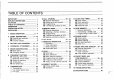
TABLE OF CONTENTS IMPORTANT EXPLICIT DEFINITIONS 14 CLOCK AND TIMER, 28 # Clock mode .. i 8 CALL i B Central description i B Calling up a call channel. i fie 4044 CAUTIONS L23 B Clock operation. i W Programming .28 B Power-on timer . :gglgvggg INTENT e I‘ W Transferring contents to VFO. . 24 M Power-off timer . OPERATING NOTES.. e 9 MEMORY MODE 15 DIME MEMORY UNPACKING i 1 8 General description..: . (Z1: General description., B Electing a memory ¢ 28 £l Transmitting a: DIME code 1 BASIC OPERATION ..
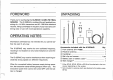
FOREWORD UNPACKING Thank you for purchasing the IC-26RA/E 144 MHz FM TRANSCEIVER. The ARCHITRAVE is a state-of-the-art handheld consisting of a 144 MHz transceiver and 50 ~ 900 MHz wide band receiver, fitting comfortably in the palm of your hand and combining ease of use with multi-operational capability. OPERATING NOTES Information overheard but not intended for you cannot lawfully be used in any way.
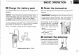
il Charge the battery pack The supplied battery pack may require a full charge prior to operation. BASIC OPERATION 1 H Reset the transceiver When first applying power, the transceiver may McGuire CPU resetting. NOTE: it your transceiver includes the battery case instead of the battery pack, remove the battery case and put in dry cell or Ni Cd batteries. (See p.14 for details) » NEVER charge a battery vase with dry cell batteries.
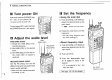
1 BASIC OPERATION @ Turn power ON Push and hold the [POWER] key for 1 sec. to wim power ON. « A beep sounds at power ON. To turn power OFF, push and hold the [POWER] key for 1 sec. again. B Adjust the audio level HAM HAM BAND AUDIO isl; VoL 1) Rotate the HAM [SQL] max. counterclockwise. 2) Sel HAM [VOL] to the desired revel 3) Set HAM [SQL]to mute the audio noise while no signal is received.
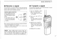
Receive a signal The transceiver can receive signals on the ham band and receiver band simultaneously. On the receiver band, the receive mode must be selected correctly. RECEIVE MODE SELECTION Push [R MAIN], then push {12 MODE] several times to select the desired receive mode: MODE ¢ It the selected mode is im: proper for therefore signal, the audio may be distorted or inaudible. s £ SR 3 Wi T Wis EM sped AN onm A SHE ; ‘ When receiving a signal, the transceiver functions as follows.
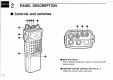
PANEL DESCRIPTION B Controls and switches Savoriness big © MAIN DIAL [DIAL] Sets an operating frequency, memory channel and SET mode contents. © RECEIVER VOLUME CONTROL [RX VOL] (p.
© RECEIVER SQUELCH CONTROL [RX SQL] (p. 3) Varies the squelch threshold point for noise mute on the receiver band. @ HAM VOLUME CONTROL [HAM VOL] b. 3) Adjusts the ham band audio level. © HAM SQUELCH CONTROL [HAM SQL] (p. 3) Varies the squelch threshold point for noise mute on the ham band, © ANTENNA CONNECTOR (p. 2) Connects the supplied ham antenna. © FUNCTION SWITCH [F} While pushing [F], all switches are set for secondary function use. (Functions written in blue are secondary functions.
2 PANEL DESCRIPTION B Front panel HAMAN MAIN wl R nm munition minster H Mol TR AT SaL a«mum :s‘r Hie ow e m i CLATTERED SHYLOCKIAN GENTLEFOLK vi scan FRIED © PRIMARY FUNCTION {written in gray): Activated by only pushing the key. SECONDARY FUNCTION: {written in blue) Activated by pushing the key while holding the [F] switch on the side panel. PRIMARY FUNCTION * Selects the ham band as the main band. Activates the transceiver for the ham band {p.3) | only.
PANEL DESCRIPTION 2 SECONDARY FUNCTION |1 OTHER FUNCTION | Selects VEO or MEMORY mode. {pgs. 17, 25) Writes the VFO contents into the memory channel or call channel when pushed and held! {pgs: 24, 26} Selects receive mode on only the receiver band: {pgs. 4. 17) No secondary function. Turns: ON the display lighting for 5 sec. (p. 48) Turns ON the display Sighting continuously. {p: 48) Calls up the call channel (p. 23) Transfers the contents in this selected memory oF call channel info the VEO. {pgs.
e 2 PANEL DESCRIPTION H Function display SOL e BT Patriarchs prisoner) o LOW SDEBEOEERDMBEE A0ERRCRNEONN -BH " 79.95 71 Stolen, it PRI %JJL’:I MAIN BAND INDICATORS (p. 3) 'f pam 7 appears above the band, either ham or receiver, Selected as the main band to be controlled, @ TIMER INDICATOR (p. 43) Appears when the power-off timer is in use, © HAM BAND FREQUENCY READOUT Shows the ham band frequency, SET mods contents or time, * The decimal point of the frequency flashes while scanning.
© S/RF INDICATORS (p. 22) Show the relative signal strength in receiving; show the output power selection’ in transmitting. *Only for the ham band's indicator. © MEMORY CHANNEL INDICATORS (p. 25) Show the selected memory channel number. * '@ appears when MEMORY mode is selected. » "% appears when the selected memory channel is set as a skip channel . " appears when a call channels selected. @ TONE SQUELCH INDICATORS [pgs. 31, 58) These indicators appear when an optional” UT:63 TONE SQUELCH UNIT is in use.
T ey L 420 BATTERY PACK CHARGING » Regular charging Connect the supplied wall charger to the [DC12.5V] jack. I Supplied wall charger BR-81 BR-84, or BRO with Ni Cd batteries, Charging period: 15 hrs. (approx.) * Rapid charging with optional BC-72 insert the battery pack into the char: ing slot of the BC-72. BP0 BATTERY CASE cannon be charged using the BC-72 ever when Ni Cd batteries are installed. Connect the wall charger supplied with the BC-72. {optional) Charging period: 1 ~3 hrs. (approx.
BATTERY PACK CHARGING 3 ¢ Charging without the transceiver To charge the battery pack separately from the transceiver, the AD:20 is available from com. AD-20 [optional} The same charger as described in “Charging with optional ) charger or cable! can be sad. BP81-84 or BP-9 Optional BC-T4AEIDIV, C Razor OP-254 must be connected to charge a BP-85: Charging period: 15 hrs. (approx.) i & * Charging notes NEVER attempt to charge dry cell batteries. Connect one charger.
Bl 4 ACCESSORY ATTACHMENT » Hand strap The hand strap allows you to carry the transceiver easily, Attach the hand strap as shown in the diagram below, 1. Insert the unstrapping a pointed tool such asa sharp pencil: 3i: Pull the hand strap to tighten the knot. 2. Put one end of hand strap through the other end's loop. * Belt clip The belt clip allows you fo attach the transceiver to your belt.
ACCESSORY ATTACHMENT 4 » Battery pack removal Push the battery pack release bunion upwards, then slide the battery pack to the right: with the transceiver facing you. To attach the battery pack, slide it until hearing a click sound. * Battery case Some versions include the BP-90 BATTERY CASE instead of the battery pack. To install dry cell batteries, open the battery case as shown in the diagram below, 1. Push the:bottom:part:ofithe battery case to open it 2. install six AN {RB) type batteries.
B Mode types MODE CONSTRUCTION The transceiver has 5 different modes and call channels for versatile, multi-function operations. VEO MODE {frequency setting) (p. 17) Used for frequency set ting ‘and normal opera: fins over the entire ham and receiver band. SET MODE (p. 29) MAIN: Used for programming infrequently used settings. The ham and receiver bands have separate SET modes. Used for operating: the transceiver using memory channel contents.
MODE CONSTRUCTION 5 ‘ Ch aging m Odes Although the following chart refers only to the ham band, the transceiver has the same modes in the receiver band, ©® = nn THEOREM Mo CALL» Y. * CLOBBER * CRUDER. CLACK. CLAMBER label In the ham ban both bands, time selling: can be performed only.
= O FREQUENCY SETTING W Selecting VFO mode When the transceiver is not in VFO mode, push [(1) VIM] once or twice o select VEQ mode. Only channel numbers or YPA of PR are indication HUE o { rite indicated here, VETO mode is not selected: 1 LYY, e i VFO mode NOTE: When the lock function is activated, the keyboard and main dial cannot be used, and the mode cannot be changed: * Lock function To prevent accidental frequency changes and Unnecessary function access, the Sock function is available.
B Setting a frequency » Using the main dial 1) Push [H MAIN] or [R MAIN] to select the desired band. » Select VFO mode if another mode has been selected. 2) Rotate the main dial to set the frequency. ¢ The frequency changes according to the fining step. ¢+ See p 21 for changing the tuning step: 3) To change the frequency quickly, rotate the main dial while pushing [F]. « See p. 21 " Dial select step’” for details.
6 FREQUENCY SETTING 2 Using the numeral keys o e SET MODE 1) Push [H MAIN] or {R MAIN] to select the desired band CHANGING THE FIRST DIGIT ] * Select VFO mode if another mode has been selected. FOR FREQUENCY INPUT 23 Push { ENT] to activate the keyboard for numeral input. The display shows the “hundreds! MHz place as the first digit for frequency input. 3) Push appropriate keys to input a frequency. » The first digit for frequency input can be sniffed in SET mode for the receiver band.
6 FREQUENCY SETTING B Tuning step The main dial or the Passkeys change the frequency in step increments. | Different tuning steps can be specified for the ham, high-frequency and low-frequency receive bands, o £ The display shows o o MY5 a0 the 10 kHz tuning step has been ! 51 selected. 3 1] 1) Push [H MAIN] or [R MAIN] 1o select the desired band. 2) Push [0 VIM] to select VFO mode if another mode has been selected. 8) Push [(5118] to display the previously selected tuning step.
L] Transmitting The transceiver transmits only on the ham band: it cannot transmit on the receiver band. Be sure the ham antenna is connected to the ham antenna connector. Transmitting without the ham antenna damages the transceiver. 1) Bush [H MAIN] to select the ham band. 2) Set the frequency. @ To select a call or memory channel see P23 orp. 25, 3) Push HI LOW] to select high or low output power.
. Bl S8 CALL CHANNEL B General description A one-touch access call channel is provided on each band. These call channels are separate from the memory channels. Use the call channel for your most-often-used frequency, You can program the following dale into a call channel. THE CALL CHANNEL ON THE HAM BAND e Operating frequency » Duplex information (DUP or.
B Programming 1) Push [H MAIN] or [R MAIN] to select the desired band. 2) Push [(DIM] fo select VEO mode. 3) Set the desired frequency to be programmed into the call channel. * Set the other data that can be programmed in the call channel if required. 4) Push [@ CALL] to call up the call channel. 5) While pushing [F, push and hold [(1) MW] until the transceiver emits 3 beeps. CALL CHANNEL 8 B Transferring contents to VFO This function transfers the call channel contents into the VFO.
[ O MEMORY MODE M General description The transceiver has 30 memory channels for the ham band and 60 memory channels for the receiver band. Use memory channels for your often-used frequencies. You can program the following data into a memory channel.
B Programming 1) Push [H MAIN] or [R MAIN] o select the desired band. 2) Select the memory channel to be programmed: = Push [(11 VM) to select MEMORY mode. (' gx8 ' appears ) Rotate the mam dial to select the desired memory channel. To select blank or masked memory channels, rotate the main dial while pushing {FL MEMORY MODE 9 3} Sel the desired frequency in VFO mode: ~-Push 105 VIM] 10 select VFO mode. Sel the desired frequency to be programmed into the memory channel: Sel the other data (e.g.
9 MEMORY MODE B Transferring contents to VFO This function transfers the memory channel contents into the 1) Push [H MAIN] or [R MAIN] 1o select the desired band. VEO. This is useful for searching for signals around the displayed memory channel frequency and for recalling the off) Select the memory channel to be transferred: set frequency, sub audible tone frequency, etc. which are Push [{1) VIM] to select MEMORY made. programmed in the memory channel.
B Masking a memory channel Unwanted memory channels can be masked (hidden). A masked memory channel cannot be selected for normal use. The contents in the masked memory channel; however, can be retailed. 1) Push {H MAIN] or [R MAIN} 1o select the desired band. 2 Elect the memory channel to be masked: Push [{1) VM to select VEO mode. ~ Rotate the main dig to select the desired memory channel, MEMORY MODE 9 3) While pushing [F], push and hold [7) MASK]. @ Frequency. etc: disappear.
B 10 SET MODE OFFSET FREQUENCY (p. 32) SCAN RESUME CONDITION (p. 35) The offset frequency is used for Timer scan of pause scan can duplex operation such as operable selected as the scan resume T nation with a repeater, m 3 condition, 5' {;‘g e o This item 18 equipped on only the ham band. o n SUB AUDIBLE TONE FREQUENCY p. 39 SCAN SKIP FUNCTION (p.
This mode Is used for rarely changed functions and settings as follows. Each band has a SET mode. o e CHGE Mo , SET MODE 10 REMEMBER ET MODE CONSTRUCTION CHART Ery iUt 145 Lt FH MHe.0G gt nrt lL!LLUU This item s ‘squnppe;s oy on the receiver band with. some versions. e Scan resume condition 1 r H5.
REPEATER OPERATION Operation L] Tone information A repeater amplifies a received signal and transmits it with SUB AUDIBLE TONE a different frequency. 'When using a repeater, the transmit {An optional UT-63 is necessary except for the USA frequency is, therefore, shifted from the receive frequency by version ) the offset frequency. ) Push SQL] to turn ON the sub audible tone encoder, 1) Push [H MAIN] to select the ham band.
L] Offset frequency s ser mope REPEATER OPERATION 11 B Sub audible tone s seT omen The: display shows the offset frequency for 800 kHz (0.6 MHz). L (An optical UT-83 Is necessary except for the U.S.A. version.) The display : shows the 885 Hz sub audible tone: frequency. 1) Push [H MAIN] 1o select the ham band. 2) Push [(1) VIM] 10 select VFO mods if another mode has been selected! 3) While ‘pushing [F], push [(8) SET] to enter SET mode » Refer fo p: 29 for SET mode details.
,= 12 Scan B Scan type Each band has 5 scan types with skip functions and 2 resume conditions to suit your needs. Scans on both bands can be operated separately or simultaneously. FULL SCAN Band edge Band edge i d : Scan Jump T Repeatedly scans all frequencies over the entire selected band. MEMORY SCAN o @D—CrD—GD -(e Repeatedly scans all memory channels except masked channels in sequence. @D Masked channel PROGRAMMED SCAN Bean edges Hand edge / \ Band edge Jump e i e Repeatedly scans between two user-progr
B Scan operations Read the following table horizontally for sate type of scan; SCAN 12 procedures in (0, @, and (8 'apply to all scan tunes. i+ SCAN TYPE | () PRE OPERATION | | () PREOPERATIVE 2| (3 SCAN START | () RESUME CONDITION SCAN STOP Push and hold TULL Psh (7D VM]to select | 12/8CAN] or SCAN 1) Push St | gee o [V/SCAN] for 1 1 MAIN] tuning sec. or [RAIN] | sleep. 1) Program the scan . ‘ PRO to select the | (p.
12 s Can B Scan resume condition The scan resume condition can be selected as a pause scan or dimer scan. The resume condition is not only used for scans but also for priority watches, Pause scan: When the operating scan detects a signal, the scan pauses on the frequency until the signal disposal pears and resumes 2 sec, laser. .
B Programming scan edges Scan edges can be programmed in the same way as memory channels. Memory channels “PA" and are available for programming scan edges. 1) Push [H MAIN} or [R MAIN] to select the desired braid. 2) Select the scan edge memory channel "PA” or "PB'L = Push [(0) VIM] 1o select MEMORY mode. (' IR" appears). + Rotate the main dial 1o select memory channel “PA" Set the scan edge frequencies in VFO made. < Push [(1) VIM] to select VFO mode.
RSN Sean @ Frequency skip function This function skips unwanted frequencies that inconvenient: Iy stop scanning during full or programmed scan. » Programming skip frequencies This Is the way to program the skip frequency when full or programmed scan is in the pause condition. Band edge Band edge Scan LT . e fume Hood for 1:sec; Vi G £ : .ME;’L E HAG 506 YR MEED et W S The frequency is programmed ina memory channel as a skip channel. The scan pauses.
s Activating (Frequency skip function ON/OFF) evasive SET MODE SCAN 12 B Setting a skip memory channel Program skip memory channels before starting memory skip scan. While the scan is activated, coll cannot program skip memory channels. MOGGY afk wflfla condition OFF condition Wi I i asap ma MEMORY mode SKIP ! appears: 1) Push [H MAIN] or [R MAIN] 1o select the desired band. 2) Push [ VIM] to select VEO mode if another mode has been selected 3) While pushing [F], push [(8) SET] ta enter SET mode.
13 PRIORITY WATCH B Priority watch types MEMORY CHANNEL WATCH SregLsncy channel While operating in a VFO frequency. priority watch checks the selected memory channel every b sec. s When the selected memory channels masked (hidden); the watch does not start. MEMORY SCAN WATCH VEQ frequency: "Meh 30 for the: ham band: While operating in a VFO frequency, priority watch checks each memory channel in sequence. » The memory skip scan can be used for horsier scanning intervals.i See ip.
N CLOCK AND TIMER 14 1 B Clock mode The transceiver has a bully-in 24-hour clock with power-on and Both the ham and receiver bands have a clock display. But, power-off timer functions. clock and timer settings are available only when the ham band is selected as the main band. VF, MEMORY mode or CALL CHANNEL ] This condition is avail ab the clock and timers.
14 CLOCK AND TIMER B Clock operation *Setting the time Only the ham band can be used for clock setting. 1) Select CLOCK mode: < Push [H MAIN] to select the ham band. Push [(0) CLOCK] to enter CLOCK mode. 2} Set the time: While pushing [F] push 1(8) SET] 1o sel the transceiver in the dime-setting ‘condition’ Rotate the main dial to set the hour. < Push [A/SCAN] or | Wisconsin, then rotate the main dial to set the minute: When a wrong time is set, push [t GLR] and begin step 2 again.
B Power-on timer ® Power-on timer operation The transceiver has a power-on timer to suit tout schedule and conserve battery power. 1) Push [H MAIN] to select the ham band, push [0 CLOCK] 1o select CLOCK mode. , 2) Push [A/SCAN] 1o select the power-on display. 3) While pushing [F], push [(7) MASK] to recall the previously set time. 4) Set the power'on time. ¢ See "Melting power-on time"" af right %ot setting the time. 5) Push and hold [POWER] to turn power OFF.
14 CLOCK AND TIMER B Power-off timer + Power-off timer operation The transceiver has a power-off timer separate from the auto power-off function (p. 47) o turn power OFF at the preset time. 1) Push [H MAIN] to select the ham band, then push CLOCK] to select CLOCK mode. 21 Push [ V/SCAN] to select the power-off display. 3} While pushing [F], push [(Z) MASK] to recall the previously set time, » @) appears.
CLOCK AND TIMER 14 [EXAMPLE]: Setting the power-off timer time to 17:30. H AN CLOCK AT: TI SCAR Y50 myna GOR My :agronomy L 27 @i Operating mode Clock:indication Froward mer KT 1AL TA CAN e 5 ——Tps %3;“5 MO0 e S B Hess Setting Power-off: timer: minute. sating condition: GENTLEFOLK = G Eme Trio MED Entering: Operating mode When tha set time of 17:30 arrives. Melting hour: }d' Bean Power. is fumed OFF.
15 MDT MEMORY ] General description The transceiver has 4 DIME memory channels for storage of often-used DEFEAT codes digits such as telephone numbers for autographing. Only the ham band can be used for programming. The programmed DIME ‘code is transmitted. oo £y Submarginal N The function display automatically shows the sending DIME digits in the sequence: of their transmission, NOTE: Manual DIME transmission is also possible. While pushing [PT, push the key of the desired DIME, digit.
[]1 Programming a MDT code 1) Push [H MAIN] to select the ham band. 2) While pushing [F], push [MDT M] to select MDT MEMORY mode. 3) Rotate the main dial to select the desired DIME memory channel to be programmed. 4) While pushing [F], push [(8) SET] to set the transceiver in the DIME programming condition. « Previously programmed digits are erased. DIME MEMORY 15 5) Push the appropriate digit keys to input the DIME code. & When entering a wrong digit, punishment] and state again from step 4.
= 16 POWER SAVER B Power saver vane SET MODE The power saver function reduces the current drain to.conserve battery power. The duty cycle of the power saver can be selected and can be turned ON of OFF. B Auto power-off The transceiver automatically turns OFF tater a selected period in which no switch Is pushed of no signal is received. Only the ham band can be used for sating this period. A RIS CIE {141 . . c MEED ofF Standby: 125 sec. 125 sec. Power saver Circuit off; 600 sec. 2 580, is trued OFF.
B Display lighting The transceiver has a display back light for night operation, The lighting confines for 5 sec., and continuous lighting s also possible: POWER SAVER 16 B One-band operation The band that is not necessary for receiving can be turned OFF. Transubstantiation conserves battery power by turning OFF the circuit of the band not displayed. LT L, unn ir sine Sassy lvr_ ¢ o Turns OFF automatically alter 5 sec.
17 PAGER AND CODE SQUELCH B General description * Pager The pager function is a selective calling system using DIME digits. With the pager, you can call any one or all the stations in your group, and you can receive a specified call from a elation in your group. To use the pager function in your group, all stations need the pager function. The transmit station sends a code consisting of a transmit code and the transmit station’'s 1D code.
[PAGER SIMULATION: Group call 10: 111 Transmitting the DIME Group: 468 code, 468 % 111! for A at ?pour tactile 1o all ] nations in the group. Bnfi flm‘ {1 Iflfl Rene Tl Beep: 10833 1D: 555 D777 Does not have Group: 468 Group: 468 Group: 468 the pager fun; PAGER AND CODE SQUELCH 17 ¢ Code squelch Code squelch allows communication and quiet standby since you will ably receive calls from stations which know your 1D code. Prior.
17 PAGER AND CODE SQUELCH B Code channel * Before programming The pager and code squelch functions require 10 codes and group code. ' These codes are 3-digit MDT codes and rust be written in the code channels before operation. » Code channel assignment ¢ 1k Your ID code
* Programming 1) Push [MAIN] or {R MAIN] to select the desired band to be programmed. # The ham and receiver bands have separate code channels. 2) While pushing {F], push [C) CODE] to select the code channel setting display. 3) Notate the main dial to select the desired code channel. 4) Push numeral keys fo enter the desired digit codes. ¢ Digits are automatically stored once the 3ed digit has been mentored. * When a rang digit is entered, push CLR] and begin step 4 again.
17 PAGER AND CODE SQUELCH Pager operation Prior to aeration, decide whether communication after the connection will take place with of without code squelch. Only the ham band can be used for pager operation. * Calling a specific station To call a specific station, use the ID code of that station as the transmit code. To call all stations in your group, use the group code as the transmit code. (PAGER CODE: Transmit code + "% +your 1D code) 1) Push [H MAIN] to select the ham band. 2) Set the frequency.
* Waiting for a call from a specific station 1) Push [H MAIN] to select the ham band. 2) Bet the frequency. 3) Push [CIPRO SOL] 1o turn the pager function ON. * “PGR! appears. 4) Once a call with the correct code is received, the transceiver emits a beep and the function display shows the code as shown at right, 5) Push [PTT] to send an answer back call. * The display shows the operating frequency. 6) Push UPGRADE SQL] once to select the code squelch or twice to select the non-selective calling system.
55 17 PAGER AND CODE SQUELCH B Code squelch operation Code squelch is a selective walling communication system using a transmit code programmed in a code channel. [tis convenient after the calling with the pager. PARASOL Push Cope: several times. YC8QL" appears. » After the calling with the pager: The transmit code Is diplomatically set. 1) Push SAL] once to turn code squelch ON. «C 5QL" appears 2) Operable the transceiver in the normal way (push [PTT] to transmit; release [PTT] to receive).
POCKET BEEP AND TONE SQUELCH 18 B General description Tess two functions are bull into the U.B.A. version. An optional UT-63 TONE SQUELCH UNIT is necessary for other versions, *Packet beep The pocket beep friction is a selective calling system using a sub audible tone. I your transceiver receives a sub audible tone that matches the phone programmed in your Fran: receiver, beeps are emitted for up to 30 sec.
57 18 POCKET BEEP AND TONE SQUELCH W UT-63 installation The UT-68 is built into the 1C-25RA U.S A version. For other versions, an optional UT-83 must be purchased separately. 1) Turn the power OFF, then remove the battery pack from the transceiver. 2) Unscrew 5 screws from the rear of the transceiver, 3) Unscrew 2 screws from the side of the transceiver. 4) Her move the rear panel. 5): Pull out the terminal board. 6} Install and plug the UT-63 as shown in the diagram at right.
B Pocket beep operation » Waiting for a call from a specific station 1) Program the sub audible tore frequency in SET mode. *Sea p. 32 for programming details, 2) Push SQL] several times until 'T SQL tea appears on the function display. : 3) When a signal including the correct tone is received, the transceiver emits beep tones for 30 sec. and flashes Glen 4) Push [PTT] or the selected band switch [H MAIN] or [R MAIN] to stop the beeps and flashing: » Tone squelch is automatically selected.
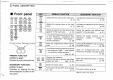
19 TROUBLESHOOTING POSSIBLE CAUSE SOLUTION « No power comes on: +The battery pack is empty. * Poor plug connection of the external DC power « Charge the battery pack or place new dry cell batteries in the battery case. s Cheek the connector or: remove the cable. be programmed. cable. « Power cannot be turned | «The battery pack beams empty during | = Charge the battery pack or place new diy cell | p. 11 OFF. operation. batteries in the battery case, then turn the power OFF.