MHL LAXITY TABLE OF CONTENTS SPECIFICATIONS o 1 DESCRIPTION 3 INSTALLATION 4 CONTROL FUNCTIONS ..o oo Sean 7 OPERATION oo INSIDE VIEW : THEORY OF OPERATION ..o noon oL 30 TROUBLE SHOOTING . i VOLTAGE CHARTS e BLOCK DIAGRAM .l 00 Celeb e s PTG P.C. BOARD LAYOUT iy ..
SECTION il DESCRIPTION SOMOZA ALL-MODE TRANSCEIVER: INCORPORATING A MICROCOMPUTER CPU control with ICBM's original programs: provides various operating capabilities. No-backwash dial controlled by sitcom's unique photo-chopper circuit. ' Band-adj detector and Endless System provides out-of-band: protection. Mo ‘variable’ capacitors or dial gear, giving problem-free use, Al mode capability:: S5B, CW. AM and FM.
SECTION 111 INSTALLATION UNPACKING Carefully. remove 'our: transceiver. from the \packing carton and examine it for signs of shipping damage.. Should any be apparent, notify the delivering carrier or dealer immediately. stating the full extent of the damages: It is recommended you keep the shipping cartons.In the event'storage, moving, of reshipment becomes necessary, they come in handy, | Accessory hardware, cables; etc., are packed with the transceiver. ‘Aka sure you have not overlooked anything.
The connection: of the DC power: cord supplied: with the: 1C551D is 'done in: the following way: Fist make sure that the power switch of the unities in the OF Position and the T/R switch sin the receive position. : Connect the cord 1o the DC power supply RED lead to the positive terminal and the BLACK lead 1o the negative terminal : [Reverse: connection will ‘cause the protraction circuit to operate and blow the fuse.): Connect the DC plug to the socket on the rear pans! ‘of the 1G-551D.
‘contacts: using a: tape recorder connected: to the headphones jag: With & stereo headphone set inserted this way, however, the headphones will Nose the sound pone side. With the plug inserted completely; only the headphones work. MICROPHONE A high quality. dynamic microphone is supplied: with your transceiver.: Merely plug it into the proper receptacle:on the front panel:: Should vou wish 1o use a different microphone, intake certain it:is approximately 600 ohms.
SECTION IV CONTROL: FUNCTIONS FRONT PANEL TELECOMMUNICATION (METER: IRE POWER :CONTROL: (MIC GAIN CONTROL (SI SQUELCH CONTROL L MIC CONNECTOR @PHONES JACK. (S POWER SWITCH (L/AF GAIN CONTROL: (REAGAN CONTROL DEMODE SELECT SWITCH {PASS BAND TUNING CONTROL CHIVE SWITCH TRANSITIVITY INDICATOR LED ZONING SPEED INDICATOR LED SE RECEIVE INDICATOR: LED INFREQUENCY.
3. POWER SWITCH The POWER Switch is a push-look type switch which controls ‘the input 'of either A Cor DC ‘‘power supplies, whichever is used. When the switch is pushed IN and locked, power is supplied o the set. ‘When' the switch is pushed: again: and released; ‘bower Is cut 1o all circuits except the CPU, if the MEMORY power supply s connected to the. MEMORY POWER terminal on the rear panel. 4; PHONES JACK Accepts ‘a standard 14dnch headphone plug for's 4168 ohm headphone set. Stereo head phones.
VED SWITCH Sates ‘an operating VFQ: from YA MFO and BY.VEQ: and: selects: the: other various ‘operations. A~ B Instantly sets the frequency of “B7.VFO to the seem as that of "AT OVEN; MS Sets the MEMORY SCAN function, Push the MS/MW Button to start scanning the three programmed frequencies in Memory Channels 1, Eng (31, A Selects A" VFQ for both transmit and receive. | "A” Shari is started by pushing the while ar this setting. B Selects: "B VFQ for both transmit and receive.
TRANSMIT/RECEIVE (T/R) SWITCH This switch is for manually switching from’ transmit To receive and vice Visa Sat the switch : to: RECEIVE {up) and the IC-651D s in: the receive mode. et the switch:to TRANSMIT {down} and it switches to transmit.. When switching with the PTT switch on the microphone forthwith the VOX switch'set 1o/ ON, the T/ switch must be in the RECEIVE position. VOX SWITCH This: switches the VOX circuit ON and OF F..
22 MALFUNCTION ‘METER . This meter: functions: as’ 2 relative RE cutout: meter in transmit mode, and: as an: S:meter {signal strength meter). receiver mode, unless: the MODE Select Switch is set at the FM«c position; in which case the meter functions as a discriminator meter in the receive mode; . TRANSMIT INDICATOR LED When your set is in the transmit mode; this LED s it TUNING 'SPEED (TS} INDICATOR LED Illuminates when the TUNING SPEED Burton is pressed to set the dial to hasten tuning.
28. ACCESSORY (ACC) SOCKET The table below shown terminal connections of this connector. NOTE: ICcRM2/3 does not function with the 1C-551D. ACC SOCKET CONNECTIONS Outside view. PIN No. FUNCTION 1 Output from squelch control stage. (+7V when squelch is ON) 2. 13.8 Volts DC in conjunction with the power switch operation. {Max. 0.3A) 3 Connected to Push-few-talk, T/R change-over switch.
33, ANT (ANTENNA) CONNECTOR This is: used to connect the antenna to the set. 1is impedance i 50 ohms and connects with 3 PL:258 connector, , 34, EXTERNAL SPEAKER JACK When an external speaker s ted, connect it to this-jack. Use a speaker with-an impedance of 8 ohms.: Sheen the external speaker is connected, the builtin speaker does not function. 35, KEY JACK Eor CW operation; connect the Key here Using the included key plug. 36. FUSE HOLDER This holds the Tues for the DC power circuit.
L4l MINI (MONITOR) CONTROL This control ‘adjusts the audio volume of the side tone {monitor) audio riding CW transmit operation. | Adjust it tour desired level for gays listening: ANTELOPE CONTROL: In VOX operation, the VOX circuit: may: be operated by sound from the speaker, casing a switch to “the “transmit: mode.
SECTION V. OPERATION HOW TO TUNE The following: instructions ‘are for tuning inane: mode.: Please: read: carefully and: understand fully before wiring ON vi our unit:: Proper tuning is necessary. for optimum operation. PRESET FREQUENCIES When the POWER switch: tend ON, the frequency display will be shown Turn the VFO Switch 10 “B". "RATBAG, and "RB-TA" positions to ses if the same frequency can be: read: on the display. Continue turning the VEO Switch to “£17 "[217 dnd "I positions 16 see i 61.000.
TUNING | CONTROL Restating -the Tuning Knob clockwise increases the frequency; turning it counterclockwise decreases the: frequency In 100Hz steps in the USB, LSB, CW and AM modes and In' 10KH2 steps in the EM made. The smaller vernier marks'on the knob represent 100Hz (kHz in'the FM mode) When you reach 53.999.9 in the SSB, CW or AM modes, or53.990.0 In the FM mode; turning the Tuning Control Knob clockwise will bring the operating frequency to 50.000.
1. The Tuning knob: tension: will become: tighter by turning the brake adjustment screw clocks wise, and will become looser by turning the screw counterclockwise; 2.5 While performing this adjustment; the Tuning knob must be turned continuously as the screw {s adjusted in ‘order to set the tension for a comfortable: touch.
18 M When the 1C8510 is first turned ON, the frequency displayed on the readout is the frequency 50.100.0MHz. FOR EXAMPLE: When:the set is turned: ON; 50.100.0 will be displayed on the readout. This will occur whether the VO Switch is in either the “A’or "B or combination VEO position.
frequency without disturbing the ‘transmitting frequency.” By pushing the RIT switch down oi ice {it's a spring loaded RIT circuit Is turned ON and the TITLED is {it. The deceive fre: quench: is:shifted with the: RIT knob. s When the RIT kapok s in the 0" position, the transmitting and receiving frequencies are the seem. Rotating the control to the 1+) side raises the receiving frequency, and rotating 1o the [} side lowers the frequency.
SCANNING 'OPERATION The 1C-551D provides various scanning operations. . Read the following instructions careful!y 10 fully enjoy the 1-881D's many capabilities: MEMORY. SCAN ‘This is to scan the three Memory Channels continuously; 1. Program three desired frequencies in Memory Channels 1; 21, and {31 2.7 Set fhe VFO Switch to the “MS position. At this time, the operating or displaced frequency is ot changed. 3. Depress the: MS/MW: Switch; 'and: the: display: frequency: starts ‘scanning the programmed .
B Program: the: frequencies: of the high and: tow ‘edge of the desired scanning range in Memory Channelized (311th does ‘not matter in which: Memory: Chanson the: higher frequency is programmed. : For instance, program 50.2MHz in.Memory Channel [Z and 50.8MHz in Memory Channel 13 Set the VEO Switch 1o "BY and the SQUELCH: Control above the threshold:: By depressing the ‘MS/MW :Button, the scan is: started from the high edge of the programmed range {60.8MH2) 1o the Tower frequency.
L22c SSB. OPERATION 1 RECEIVING After connecting an antenna, microphones, 816, set knobs and switches as follows. POWER SWITCH OFF: {button-out position) T/ WHICH RECEIVE {UP) VOX SWITCH OFF{UP) AGC: SWITCH SLOW (UP) NB {NOISE BLANKER} SWITCH OFF (UP) MODE SELECT ‘SWITCH USB or LSB VFO SWITCH GAIN CONTROL: Sully Counterclockwise RE .
For normal SS8 reception, set the AGC switch in ‘the UP (slow) position. Set the AGC switch in the FAST {down) position, when tuning or receiving signals with short interval fading. When in the FAST position, the time constant is shortened. P.B. (PASS BAND) TUNING The Pass Band Tuning unit is a system in the receive mode 1o narrow the band width {selectivity) of the frequencies that will: pass through the crystal filter electrically from either the upper or lower side continuously by up to kHz.
Other knobs and switches are left in the same positions as for receiving. When the T/R switch {5 moved to transmit; or when: the PTT {push to talk) switch on'the microphone is depressed, the transmit LED: Js illuminated.. | By speaking: into: the.
stop talking) is controlled by the VOX DELAY control.: Turning the control counterclockwise drakes the time shorter, [ Bet it ata position chichis comfortable and which mafioso for short pauses in normal speech: ‘Adjust the ANTELOPE control sol that the: VOX circuit is ot activated by sounds from: the speaker by turning the contra clockwise while receiving a signal. CW OPERATION 1 2. RECEIVING For CW reception; set the MODE Select: Switch to the CW position.
=26 AM OPERATION 1. RECEIVING Set the MODE Select Switch fo “AM”. " Turn the Tuning Knob to that the beat caused with the AM signal carrier becomes a ''zero beat”™ Brainstorming AM signal’s carrier and lower side band signal are:removed with the crystal filter, and the: resulting upper side band signal is fed to the detector, the same for SSB detection. Therefor, ‘the other procedures are the same as for S5B reception.
2. The NOISE BLANKER and the AGC circuits do not actuate in this mode. TRANSMITTING Set knobs and switches as Hollows: MIC: GAIN CONTROL Center (12 o’clock) position RF POWER: CONTROL Completely Counterclockwise [COMP: OFF position) Other knobs and switches are left i the same positions as for receiving: Tum the T/R switch to TRANSMIT or push the PTT {push to talk} button on the microphone and the: transceiver will transmit.
TRISECTION Vil THEORY OF OPERATION OUTLINE The 1C-BS1D ‘employs a digital ‘phase Socked loop {PLL} circuit as the local oscillator for goth Transmit and: receive. The output of ‘the PLL circuit is approximately: MHz below the receive frequency; thereby spurious is kleptomania minimum: The: operating frequency s controlled: by pulse signals, generated: by ‘the optical chopper circuit Located at the tuning knob, being added to or subtracted from the preset francium in the micro: Computer.
RF CIRCUIT Mitered signals from the double-helical cavity filter, which reduces interference and intermediate: son farm other radio signals or nearby signals, are fed to the bridge attenuation consisting of 128 D23, €95 and C96: RF gain control and: AGC voltage'is added to diode D23; which changes the balance of the bridge to control the input signal Revel.
32 MHz) result in signals of 10.7512MHZ 10 10.7488MHz all signals will pass through the filter. NEMBUTAL centered Output: Signals Pass band of © Output Signal of MAIN unit Fi1 of Mixer 8 i Output Signals i ; of Mixer Filial [KHz) 9015 [k b Mtz an MK Turning the:Pass Band Tuning control fury clockwise, the VX0 Frequency:will become 19.7630 Mz {19:7615+ L5KHzE: When mixed with:the commingling B.0115MHMz signals, the resultant frequencies: become 10.
The signal which has passed through the pass band tuning circuits is amplified by a three-stage amplifier consisting of litigate MOS PET's 02, O3 and 4. Tess amplifiers provide high gain and high stability, and-the: IF coils and L11 eject interference from outside the IF pays band and other wide-range noise.
A TRANSMITTER CIRCUITS MICROPHONE -AMPLIFIER :AND: LIMITER CIRCUIT Audio signals ‘from the microphone ‘are: fed 16 Pin: 6:of the audio amplifier 1C6/2: Amplified signals appear at Pin 7.and are sent through G172 and J4 1o the MIC GAIN control variable resistor on the front panel. Adjusted signals sre fed to Pin 2 of 1C5/1 through €171, D45 and C170in the EM mods, ‘as D4E is turned ON by the voltage supplied through B1B8; and through C171.
but this is completely removed by the crystal fitter Ei1.0n the MAIN unit; and the final signals s clean and powerful SSB signal, TRANSMIT MIXER: CIRCUIT. High quality PET's OB and 07; and-coll L17 and 1.18 work ss & double-balanced mixer to provide Tow spurious generation and excellent mixer characteristics. The local oscillator signals are supplied to:L18 through D7 from the PLL circuit and mixed with the AM, Boris CW signals fed through D8 from Fl1.
=36 APICAL CIRCUIT ‘This circuit stabilizes the output powder, even when the power vantage ior ‘the antenna Joan s fluctuating, and sets the ‘output: power between: 1 and 80 watts. The variation in the collector current of Q2 s detected at R6 and amplified by differential amplifier 1IC1/1. The output voltage from Pin: 7 of ICTUS s fed to the second gate of 05 to stabilize the RF output power. In the 558 mode, ‘when output signals are higher than the saturation level, 08 and Q9 are tied ON.
base' of ANTELOPE detector Q2 and its output of the sitter is supplied o the other base of 03, The emitter voltage of O3 is changed 1o ground level by turning ON O3 to cane! the VOX signals. In the CW mode, the keying signal s fed 1o the base of Q10 through R33 and keys the input terminal of the BRD, 1C4. The time-delayed keying signal. the output signal of 104 is ted to the base of Q7 and switches 06 corresponding 16 keying.
=38 POWER SUPPLY CIRCUIT Regardless of whether the transceiver is switched to the receive mode or not, power is always supplied from a constantly activated source to the receiver AF amplifier, the transmitter microphone amplifier circuits:and VOX circuit BFQ and Cw monitor circuits are supplied through the mode switch.
The crystal unit X2; a special VXO (Variable Ital Oscillator) crystal, is constricted to 03's base and oscillates at about 1B.0T0MHz2. | The oscillating frequency is altered in 100Hz steps by the voltage stippled to the anodes of D3 and DA from the D/A (Digital to ‘Ana tog) converter through 1C6/2 operational amplifier. The MHz signal is doubled at 4, has the local oscillator out bot between 36.0186MHz and 36.0284MHz Is obtained. The cathodes of D3 and DA are connected to the BIT.
LA steps is set by the 100Hz step variation of the Local oscillator: (V X0} frequency.
Q10 ON. The voltage at the emitter of 010 becomes approximately 0.6V below the voltage at the base of Q10.: Thus the input voltage of regulator IC7 is regulated at the tonal of the zither vantage of D2 and the emitter voltage of Q10. When the input voltage of 1G7 varies, the emitter voltage of Q10 varies because ‘the: zen er voltage is stable.: The variation: in the voltage controls Q9 by corralling thi base current of Q9. Thus the input voltage of 1C7.is regulated.
cag As these 90 degree out of phase signals are similar to @ Sine wave, the signals are converted into logic level signals which have vary hart rise and fall times by the Schmidt trigger circuits of ICT With the folic level signals, clack pulse signals (CK 1, 2) and RUBDOWN rials (UD] are generated: by: the UP/DOWN control recruit; TIMING CHART When ths tuning knob is turned When the tuning knob is Wined clockwise counterclockwise /\ & o N lee The flip-flop of (@ (1/2 1C2) and & {1/2 1C3) functions as a qua
fed through D4 and D6 1o the K1 M and K2 ® terminals of the CPL ‘At the same tine, an UP or DOWN signal fed through D3 to the K8 & terminal; The output of D3 becomes H-level at the UP count and Li level at the DOWN count. K1 and K2 data ave added to or subtracted from the preset frequency {60, MHz) according to the UP/DOWN signal.
(DIAL: LOCK} This flow occurs when the dial lock switch s set in the lock position, UP) This flow occurs when the frequency is moved up by turning the tuning control knob. When the frequency is moved down, the R2 signal is not fed (Memory 1) This flow scours whee the VRO select switch s set at "Memory (Memory @) This flow occurs when the VEQ select switch s set at ""Memory 27, B3 K4 (Memory 3} This flow occupiers when the: VEQ select switch is set at “Memory 37 In the condition: of (8}, .
R5 = K4 (RT) RS =+ K8 (DBC) These are used whine an external controller is connected to the unit. (STOP 2 Mode) This flow: occurs when: the scan is stopped automatically. In this condition; the scan starts automatically: from the frequency the scan has stopped at with the signal from the scan stop control circuit. 23 RE-SMUTS) This How occurs when the TS button is pushed. This flow otters when the Unit 18 set in the transmit mods. The scan operation ‘stops auto. manically.
46— CPU MALFUNCTION-PREVENT: CIRCUIT This circuit s to prevent the CPU from malfunctioning which: may be caused by repeatedly turning the power ON and OFF, or by chattering when the power connector is plugged. The cause of this malfunction s that (C7 starts recharging before it discharges: Completely and the Challis not initialized: To prevent this; Od is turned ON and C7.
€20 50 that QB is turned DEE, and the nonadjustable multi vibrator, consisting:of 1C12 and ICC; operates with the: time constant set by ‘R28 and €5, -In the other scan mode, O5 s turned ON so that the scan speed is decided by the teems constant set by C5, R42, R28 and the scan speed control R203 under the access cover. The K2 input signal is read and its positive edge and variegate edge is detected by the CPU program. The CPU synchronizes to-this period and decides the scanning speed.
SCAN STOP BY A RECEIVED SIGNAL While scanning, when a signal is received, SOL 'S signals fed from Pin 7 of IC6 on the Main Unit.
IN. THE SCAN B’ MODE SCAN START/STOP ‘The scan START and scan STOP 1 function by Use of the MS/MW button, and scan STOP 2 functions by receiving a signal, are the same as the operations for SCAN YA mode. AUTO SCAN START In the SCAN “B” mode, the scanning stops by receiving a signal. After approximately 16 seconds; the Sean re-starts automatically: In SCAN: “B" mode, Pio 4 of 1C11 and Pin 4 of ICC is shunt to-ground through D37 so that the output signal from Pin 13 of 1G13 does not reset Pins 125 0f ICC.
SECTION VI 'TROUBLE SHOOTING Your 1G:5510 has been tested very carefully at the factory before shipping. The chart below has bean: designed to help you correct any problems which are not equipment malfunctions. £ you are not able to locate the problem and/or solve it through use of this chart, please contact your B0 dealer or ICON distributor for assistance: Problem Possible Hausa Solution .
| SECTION IX. VOLTAGE CHARTS NOTE: Measuring instrument is a 50K$2/V mu altimeter. MAIN UNIT TRANSISTORS ' (in the USB mode and RF POWER control in Hhe COMP OF F position.
PLENITUDE Talents ails NEV ARKS Princeton o ic2 [Bolonn32(s0 800 ics Tzelaz/320 [T4l1alG0 0T Ics 10 [76(68 39125 6ol o [0 5 Renee als JCTTL2IGND 8.0 Tin i T4V or OV according to operating frequency. 8.0 re0 s Wave form of IC1 Pin 2 : Wave form of 1C3 Pin 7 DRIVER UNIT TRANSISTORS TRANSMIT RECEIVE RN Eggs Emergent ngs ‘ Emerge Hearken WATERGATE) DRAIN' © | SOURCE [LITIGATE DRAIN | | source 068 065 g 0.85 0.6% 0 a7 138 86 138 {138 86 138 as 068 138 a 065 138 a Q8 a 138 Q.
R OUTPUT TIMING CHART Each Output has'a 0.4 milliseconds interval.
PBT UNIT. TRANSISTORS {In the USB mods and RF POWER ton teal in hick ON position.) TRANSMIT RECEIVE B 7o, | BASE collector Base COLLECTOR [EMITTER | dynamics GATE GATE) RAIN. | SOURCE 510 005 Lok 103 G710 aio oND oND Giz GND a0 o1 b GND Q14 VOX UNIT TRANSISTORS TRANSMIT RECEIVE e | S| Jolson HOTTER VA0 | [enumerator [T | mes GATE GATE bra In | SOURCE Use GNP 49 | LsB GNG. | use Grind | Use oup avo aio VOX UNIT 1C (in the USB mode.
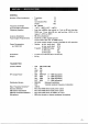
OPTIONAL AC POWER SUPPLY 1CPS20 ‘This set s designed to operate on 13.8 Volts: DG However, a special AT power supply the IC-PS20 is available for AG operation. ‘The 1C-PS20 provides 13,8 Volts at 20 Amps. ‘When connected to the 1-6510 transceiver, the power supply ON-OFF aeration is remotely controlled by the power WON-OFF switch on the 1C-551D; M SPECIFICATIONS .