EMERGENCY USE 11 our vessel requires assistance, attract the attention of other vessels and the Coast Guard by sending a distress message on Channel 16, Procedures for sending a distress signal. 1. MAYDAY, MAYDAY, MAYDAY {(repeat three times) 2. THIS I8 (name of the vessel} 3. LOCATED AT (gives position) 4. Give the reason for the distress call. 5. Explain what assistance you need. 6. Give additional information to help those come to your assistance, (vessel length, color, type, enc) 7.
INTRODUCTION You are now the proud owner of one of the finest VHE FM Marine Transceivers on the market today. |t was designed and built by COM: INCORPORATED, a long time leader in the field ‘'of VHF communication.. We put all the technology, and experience we have gained over the years in a transceiver that was built from the ground Up: specifically for Marine,: We know that your 1C-MBO will ‘give vou bears of enjoyment and dependable communication.
FEATURES All marine channels plus weather per-programmed. Weather and dust-tight case: molded frame. All solid state including the 25 watt Power Amplifier modifiable. % No moving controls inside « PA and RF switching are solid state, A snap-in mounting bracket, adjustable angle; lockable for security. * Advanced RE front epd with helical resonators; MARMOSETS, and crystal/mechanical filter for adjacent channel and inter modulation rejection. * \Auto Monitor for Channel 16, * [High power, distortion-free aud
INSTALLATION Planning Select a location for your transceiver which will allow free access to the front controls, good: air circulation and rear clearance for access o the fuse and cable connectors. Provide the best protection you can from direct rain pyorrhea seas. Avoidant cable ‘transitory the antenna and power Source. AL the same time, keep power and antenna cables as irresponsible from: electrical ‘sources ie; generators,: alternators; electrical pumps. etc.
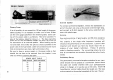
Primary Fowler If at ail possible, do not exceed the 10 feet length of the power cable supplied it it 1s necessary 1o make a run of over 10 feet use the wire gauge specified in the following table.
Accessories 1:: Mounting Bracket 2. Power Cord and Microphone Hanger Box 3. Mounting Screws 4. Mounting Washers 5. Mounting Nuts 6. Keys 7. Fuses 10A 8. Microphone Hanger Box Mounting Screws PER-OPERATION Licenses Required 1: Ship Stetson License Your craft, when equipped withheld equipment, has a radio station on bond which, if used, must have a current license. | It Js unlawful 10 operate a Ship Station which' Is ‘not: licensed.
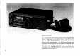
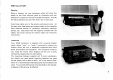
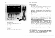
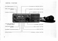
CONTROL FUNCTIONS BRE POWER SWITCH—— USES {DUAL WATCH) G BUTTON T [SQUELCH CONTROL (VOLUME CONTROL and POWER SWITCH SWEATER CHANNEL . BUTTON § @CHANNEL ALLOCATION SWITCH — 12 CHANNEL and FUNCTION: DISPLAY MEMORY WRITE/DIMMER BUTTON MEMORY: READ:BUTTON AD CHANNEL SELECTOR @ DAL SELECT BUTTON J0 SCAN BUTTON (LOUDHAILER SWITCH (Z.
SQUELCH CONTROL Controls squelch threshold: level which quiets the receiver when no signal is present. VOLUME CONTROL and POWER SWITCH By pushing ‘this knob; this switches ‘the ‘power supplied to the radio ON and OFF. By toning this Knob; this controls: the audio output level of the receiver: RF "WORE SWITCH Switches the transmitter: output power. ln the :CLOY Dominion, the power is 1 watt, sufficient for focal communication.
10 13. MEMORY. WRITE/DIMMER BUTTON Transfers your desired channel into @ memory channel, and enables the channel selector to change the intensity of the display. 14, MEMORY READ BUTTON Sets the radio toa memory channel which is selected by the channel selector. ADDITIONAL CONTROLS 1. Microphone Hanger Box Triggers the Channel 16 ‘Auto:Monitor circuit when the microphone i3 replaced in the hanger. 2.
i channel: number hare misplayed neither: CHANNEL and UNCTION DISPLAY. 6. When vou wish 1o monitor g weather channel, push the (5 WEATHER CHANNEL ' BUTTON, then rotate the Chanel: Selector to the desired weather channel: At this ‘time, the letters of "WX'% and selected weather channel number {0~ 9} are displayed: on the CHANNEL and FUNCTION DISPLAY.
12 rascally return to: Saccharine 160 (Before Transmitting, bhe sure that the 8 RF POWER SWITCH is in the proper position for the distance and needs of your contact: Use 25 watts only when necessary, 10 avoid interfering: with others: trying to use the same channel in another area.) MEMORY CHANNEL OPERATION Memory Writing {Programming the Memory Channels) 1. Push the (3 MEMORY READ BUTTON end a memory channel will be displayed on the CHANNEL and UNCTION DISPLAY, 2.
BUTTON, and a channel number is displayed on the CHANNEL and FUNCTION DISPLAY. Depressing the & SCAN BUTTON starts the sen from the displayed channel to the highest channel {Channel 88). 1 the SQUELCH is not engaged. the scan does not start; 2. When the scanning channel reaches the highest chains! it automatically returns to the lowest channel {INT: Chan. nel 1, USA: Channel 8], and continues scanning up to provide endless'scanning operation. 3.
14 returns to operate neither other channel: L Select the channel 16 by pushing the 7 CHANNEL 16 SELECT BUTTON: then engage the SQUELCH, Select your desired channel by pushing the @ DIAL SELECT BUTTON, @ MEMORY READ BUTTON or {5 WEATHER CHANNEL BUTTON 'depending on your desired channel}, and turning the 45 CHANNEL EELS: CTR. Push: the: @ -SEA (DUAL WATCH) BUTTON, -and the radio -operates on-the selected channel for two or three seconds and “on channel 16 for @ moment {about 0.1 second) alternately.
OPERATING RULES AND GUIDELINES Prevent Interference Before: transmitting, Monitor the channel you wish to use to avoid interrupting transmissions in:progress: Call Procedures Calls: must be properly identities: and time: limits must be respected. 1. Give your call sign each time you place a wall to another vessel or a “coast station: {1 a call sign has not been assigned, identify the station by announcing the vessel name and the name of the licensee.) 2.
16 Channel usage A channel selection system, frequency-usage, has been inter: nationally adapted for the marine VHF band. Each frequency within the spectrum hos been assigned @ channel number, for example, 156.300MHz is Channel 6. Specific purposes have been: assigned to each channel under this system i.e. internship between ‘two vessels and ship-to shore. Geographical locations have specific channels assigned for use with the land telephone system.
MARINE VHF RADIOTELEPHONE CHANNEL FREQUENCIES Function o Ship Ship Mode Only Only Ship -1 hippo Channel Transmit | Receive §B ind Com LISTING 1 i Ship, Those Type ot Operation 1 156.050 1 180.650 o yes no yes Public Correspondence, Port Operation 2 156.100: 1 160,700 D yes no ves Public Correspondence, Port Operation 3 1568150 1160750 D yes no yes Public Correspondence; Port Operation 4 156.200: 1 160.
18 Unction Ship Ship Muse: Only: Only Ship 1 Township Channel | ‘Transmit || Receive §/B Saki Com use Ship Short ‘Type of Operation 60 156,025 L yEs: no yes Public Correspondence, Port Operation 61 D yes no yes Public: Correspondence, Port Operation 62 156125 160,725 3 Y65 no yas Public Correspondence; Port Operation 63 166.175.1.160.775 D yes. o yes Public Correspondence, Pact Operation B4 156,225 1160825 0 yes He Vs Public Correspondence, Port Operation’ 65 156.
MINOR TROUBLESHOOTING Your: 10-M80: has been design-engineered to provide years of trouble free operation.
20 TRANSMITTER LOG RADIO SET SER. NO: Date: initial Reading Date Date Date Date Date Date Transmitter RE Power Quip Transmitter Deviation Transmitter Frequency CH Transmitter Frequency CH 6 TECHNICIAN SIGNATURE, ADDRESS, FCC LICENSE NO.